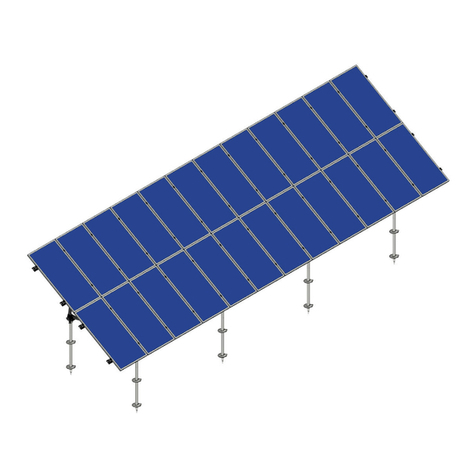
Mounting Systems Sigma Tracker User manual

Sigma Tracker
Installation Manual
Photovoltaic system
Horizontal single-axis tracker as per EN 62817
Tracker name:Sigma Tracker
ENGLISH
Copyright © 2020 Mounting Systems GmbH - All Rights Reserved.

2/60
ST_PM_ Installation Manual_EN_V1.0 | 08.2020 Copyright © 2020 Mounting Systems GmbH
1Table of contents
1 Table of contents .................................................................................................................................................2
2 Product type / model ..........................................................................................................................................4
2.1 Manufacturer ................................................................................................................................................................4
2.2 Document number.......................................................................................................................................................4
2.3 Important notes about these instructions............................................................................................................4
2.3.1 Purpose of the document.....................................................................................................................................4
2.3.2 Target group............................................................................................................................................................4
2.3.3 Symbols used...........................................................................................................................................................5
2.3.4 Other applicable documents..............................................................................................................................5
2.3.5 Storage of the document.....................................................................................................................................5
2.4 Legal disclaimer ...........................................................................................................................................................5
2.4.1 Disclaimer .................................................................................................................................................................6
2.4.2 Guarantee ................................................................................................................................................................6
2.4.3 Warranty ...................................................................................................................................................................6
2.4.4 Copyright and trademarks ..................................................................................................................................6
3 Safety requirements.............................................................................................................................................7
4 List of tracker components.................................................................................................................................9
4.1 Main components........................................................................................................................................................9
5 Goods receipt, transport and storage ............................................................................................................11
5.1 Goods receipt.............................................................................................................................................................. 11
5.2 Transport and storage.............................................................................................................................................. 11
5.2.1 Storage..................................................................................................................................................................... 11
6 Installation........................................................................................................................................................... 12
6.1 Cabling ......................................................................................................................................................................... 12
6.1.1 Network ................................................................................................................................................................... 12
6.1.2 Motor cable ............................................................................................................................................................ 12
6.1.3 Sensor cables ........................................................................................................................................................ 12
6.1.4 Modbus cables...................................................................................................................................................... 12
6.1.5 Potential equalisation......................................................................................................................................... 13
6.1.6 Cable trench .......................................................................................................................................................... 13
6.2 Pile-driven support post.......................................................................................................................................... 14
6.2.1 General driving tolerances ................................................................................................................................ 14
6.2.2 Adjustment dimensions for motor stanchions .............................................................................................. 14
6.3 Post extensions and motor mount........................................................................................................................ 16
6.3.1 Tools and equipment........................................................................................................................................... 16
6.3.2 Work steps.............................................................................................................................................................. 16
6.3.3 Installing the post extensions ............................................................................................................................17
6.3.3.1 Installing the motor mount....................................................................................................................... 18
6.4 Rafter installation ...................................................................................................................................................... 19
6.4.1 Tools and equipment........................................................................................................................................... 19
6.4.2 Work steps.............................................................................................................................................................. 19
6.4.3 Install rafter ........................................................................................................................................................... 20
6.5 Adjustment device and spindle holder................................................................................................................ 21
6.5.1 Tools and equipment........................................................................................................................................... 21
6.5.2 Work steps.............................................................................................................................................................. 21
6.5.2.1 Installing the adjusting device ...............................................................................................................22
6.5.2.2 Set horizontal alignment to 0°................................................................................................................23
6.5.2.3 Mounting the spindle holder tube on post extension ..................................................................... 24
6.5.2.4 Mounting the spindle holder tube on spindle.....................................................................................25
6.5.2.5 Mounting the spindle stopper at the spindle .....................................................................................26
6.6 Installing the geared motor and chain drive .....................................................................................................27
6.6.1 Tools and equipment...........................................................................................................................................27
6.6.2 Work steps..............................................................................................................................................................27
6.6.2.1 Installing the motor....................................................................................................................................27
6.6.2.2 Installing the chain drive ..........................................................................................................................29
6.6.3 Installing the trap torsion ring........................................................................................................................... 31
6.6.3.1 Connecting the motor.............................................................................................................................. 34
6.7 Installing the torque tubes......................................................................................................................................35
6.7.1 Tools and equipment...........................................................................................................................................35
6.7.2 Work steps..............................................................................................................................................................35
6.8 Module carrier rails....................................................................................................................................................37

3/60
ST_PM_ Installation Manual_EN_V1.0 | 08.2020 Copyright © 2020 Mounting Systems GmbH
6.8.1 Tools and equipment...........................................................................................................................................37
6.8.2 Work steps for installation of mono-facial module rail system...............................................................37
6.8.3 Work steps for installation of bifacial module rail system ........................................................................39
6.9 Compensation pile-driving tolerances on the torque tube ......................................................................... 42
6.10 Potential equalisation ............................................................................................................................................. 42
6.11 Module installation................................................................................................................................................... 45
6.11.1 Tools and equipment.......................................................................................................................................... 45
6.11.2 Work steps for click-stone................................................................................................................................ 45
6.11.3 Work steps for screw connection.................................................................................................................... 46
6.12 Control unit..................................................................................................................................................................47
6.12.1 General installation instructions.......................................................................................................................47
6.12.2 Electrical connection .......................................................................................................................................... 48
6.13 Frequency inverter.................................................................................................................................................... 48
6.14 Installing the tilt sensors ......................................................................................................................................... 49
6.14.1 Tilt sensor cabling connection at the sensor............................................................................................... 50
6.14.1.1 Work steps ................................................................................................................................................... 51
6.14.2 Tilt sensors calibration ........................................................................................................................................ 51
6.14.3 Wind sensor Installation .....................................................................................................................................53
6.14.3.1 Connecting the main supply .................................................................................................................. 54
6.15 Emergency power supply ....................................................................................................................................... 54
6.16 Met masts ....................................................................................................................................................................55
7 Legal information ...............................................................................................................................................57
7.1 Published by................................................................................................................................................................57
7.2 Picture credits.............................................................................................................................................................57
8 Index of illustrations...........................................................................................................................................58
9 Revision history ...................................................................................................................................................59

4/60
ST_PM_ Installation Manual_EN_V1.0 | 08.2020 Copyright © 2020 Mounting Systems GmbH
2Product type / model
Product: Sigma Tracker
Abbreviation: ST
Product type: HSAT (Horizontal Single Axis Tracker)
Module installation: 2 PV modules installed vertically
The module installation, size and number of modules may vary depending on the project-
specific requirements.
2.1 Manufacturer
Mounting Systems GmbH
Tempelhofer Weg 39–47
D 10829 Berlin
GERMANY
Telephone: +49 30 328972 -100
Fax: +49 30 328972 -199
info-de@mounting-systems.com
If you have any questions, please first contact your supplier.
2.2 Document number
ST_PM_Installation Manual_EN_V1.0
2.3 Important notes about these instructions
2.3.1 Purpose of the document
This document is intended to permit the correct and safe installation and commissioning
of the product, as well as serving as a training document and reference work for power
plant operators.
Read these instructions along with all other applicable documents before starting work
and train your staff accordingly.
2.3.2 Target group
These instructions are intended for all persons representing both contracting partners,
especially professionals and trained personnel.
A professional is anyone who, by virtue of their vocational training, is able to carry out
installation and commissioning work in a correct and professional manner.
Trained personnel refer to anyone who has been appropriately trained for the assigned
tasks and instructed about the potential dangers resulting from incorrect behaviour.
A trained person must have been instructed in the necessary devices, safety measures,
relevant regulations, accident prevention guidelines and operating conditions and have

5/60
ST_PM_ Installation Manual_EN_V1.0 | 08.2020 Copyright © 2020 Mounting Systems GmbH
demonstrated their ability to comprehend these. The work carried out must be signed off
by professionals.
Third parties are persons who do not have any relationship with either of the two
contracting parties.
2.3.3 Symbols used
The following symbols indicate warning and safety instructions, as well as important
information regarding various operating sequences.
Warning of a hazard
This symbol indicates that particular care and attention are required.
Warning of hazardous electric voltage
When working on or near live parts, particular care and attention are required.
This work should only be carried out by appropriately trained and authorised
professionals.
General notes
This symbol indicates important information and useful notes.
2.3.4 Other applicable documents
The following documents apply in addition to these instructions:
•Operating and maintenance instructions
•Project-specific layout drawings
•Control cabinet wiring diagrams
•Project-specific parts lists and spare parts lists
•Project-specific statics
•Reports
2.3.5 Storage of the document
These instructions should be read carefully and stored so that they are accessible to
operators of the system at all times.
2.4 Legal disclaimer
All users must be familiar with the employed warning and safety notes. It is essential to
take account of and adhere to all the specifications made in these instructions in order to
ensure safe and correct operation.
All issues relating to feed-in and technical issues must be clarified during the planning
phase with the responsible network operator (energy supply company) and
corresponding agreements made.

6/60
ST_PM_ Installation Manual_EN_V1.0 | 08.2020 Copyright © 2020 Mounting Systems GmbH
2.4.1 Disclaimer
No liability or responsibility will be accepted in respect of any loss or damage resulting
from any failure to comply with the safety-related provisions set out in these instructions.
No responsibility will be accepted for the infringement of other third-party rights that
result from the use of this product.
The operator has the sole responsibility for protecting the power plant system against
access by third parties or taking additional measures to this end if required. The
manufacturer reserves the right to make changes to the technical data of this product or
these instructions without prior announcement or notification provided that such changes
do not relate to safety regulations or CE conformity.
It is prohibited to make changes to the photovoltaic system. Any misuse will result in the
cancellation of the warranty, guarantee and any liability on the part of the manufacturer.
This also includes modifications to factory-set parameters of system parts.
2.4.2 Guarantee
The product guarantee applies in accordance with the current warranty agreements, the
general terms and conditions of business and the additional contractual provisions
concluded with the supplier.
2.4.3 Warranty
The legal framework conditions of the country of manufacture apply. Any further-
reaching agreements must be set out contractually with the manufacturer prior to the
awarding of the order.
2.4.4 Copyright and trademarks
All specifications made in this documentation are confidential and are subject to
copyright law. This documentation must not be supplied to third parties without the
manufacturer's approval.
“Mounting Systems” is a registered trademark of Mounting Systems GmbH. Safety
requirements. The operator must ensure that each person instructed to carry out
installation work can show evidence that they have received appropriate professional
training.
This document is confidential and only for the information for the intended recipient and
may be not used, published or redistributed without the prior written consent of Mounting
Systems GmbH.

7/60
ST_PM_ Installation Manual_EN_V1.0 | 08.2020 Copyright © 2020 Mounting Systems GmbH
3Safety requirements
All technicians must have read and understood these instructions and must comply with
them at all times, in order to:
•Prevent hazards to life and limb.
•Safeguard the operational safety of the tracking system.
•Rule out any system downtime or environmental impacts resulting from incorrect
handling.
Failure to comply with the safety regulations listed below may result in serious
injury or even loss of life.
All electrical work must only be carried out by trained electricians.
No work may be carried out on electronic or electrical components while they
are live.
The tracking system may only be supplied through a TN-S network system.
Only PV modules of protection class II or IEC application class A may be
installed.
Only dual-insulation DC cables approved for photovoltaics (protection class II)
may be used.
The DC cabling may only be secured to the tracker parts designated for this.
The DC cabling must be installed so that it is resistant to grounding faults and
short-circuits.
The operator must provide string monitoring through the inverters.
All work must comply with the country-specific safety regulations.

8/60
ST_PM_ Installation Manual_EN_V1.0 | 08.2020 Copyright © 2020 Mounting Systems GmbH
For the entire duration of the installation and commissioning work, only
authorised, skilled specialists and authorised, trained personnel may enter the
installation area. The operator must ensure appropriate protection.
Personal safety equipment must be worn by anyone commissioned to work on
the tracking system.
The operator must ensure that nobody enters the installation area and that no
work is performed during extreme weather conditions such as storms, heavy
rain, lightning, etc.
Only original components may be used. The original components may not be
modified without the manufacturer's permission.
The photovoltaic modules may only be mounted in the safety position.
Carry out all work carefully and with the safety aspect first.
During all work, note the relevant regulations relating to safety in the
workplace and environmental protection.
Note the instructions on the type panels and warning signs throughout the
system. All signs must be recognisable, legible and free of dirt. Replace any
missing signs.
Keep fastening materials for safety devices safe if they are removed. Reattach
removed safety devices before commissioning.
Do not carry out any welding work in the area of the power plant.
Do not clean the geared motor or control cabinet with high-pressure cleaning
equipment or sharp-edged tools.
Note the permissible tightening torques of the fastening bolts.
Replace any bolts that have become unusable with new bolts of the same
strength class and design.

9/60
ST_PM_ Installation Manual_EN_V1.0 | 08.2020 Copyright © 2020 Mounting Systems GmbH
4List of tracker components
4.1 Main components
Figure 1 Tracker components
A
Drive unit
7
Motor post
7-1
Motor bracket
11
Geared motor
12
Chain drive
B
Support post
6
Pile-driven support post
5
Post extension
3
Rafter
9
Scissors jack
9
Spindle holder
C
Torque tube
10
Torque tubes
10
Connector
10
Retaining rings
D
Module carrier
2
Module carrier rail
2
Rail connector
2
Module fixation rip screw
E
Control cabinet
E1
Control cabinet
E2
Cabinet pile (optional)

10/60
ST_PM_ Installation Manual_EN_V1.0 | 08.2020 Copyright © 2020 Mounting Systems GmbH
F
Components not shown
F1
Mounting tools
F2
Parameter loader with pre-programmed memory card
F3
Control software pre-installed on memory card
F4
Cabling (optional)
F5
Met mast 10m (optional)
F6
Wind sensor
F7
Tilt sensors

11/60
ST_PM_ Installation Manual_EN_V1.0 | 08.2020 Copyright © 2020 Mounting Systems GmbH
5Goods receipt, transport and storage
5.1 Goods receipt
The delivered goods may only be accepted by authorised or trained personnel.
All deliveries must be inspected immediately upon receipt for completeness and
any transport damage! The sender must be notified of any damage without
delay. The nature of the damage must be documented as accurately as possible
on the freight documents and must be confirmed by the carrier. It is advisable to
take photographs of the delivery. In the case of major damage to freight, an
expert must be consulted and the supplier must be informed. The content of the
goods delivery is listed in the shipping documents.
Do not open or damage any parts of the packaging which are designed to
preserve the goods.
Transport damage may impair the proper functioning of the components.
Do not use damaged components.
5.2 Transport and storage
The suppliers' packaging guidelines and regulations must be observed during the
entire transport chain. For individual weights and dimensions please refer to your
project-specific documents.
The weights of the individual packing units are stated on the delivery note.
Avoid excessive physical shocks and vibration.
All parts must be protected against mechanical shock and vibration during
transportation and storage. It is important to protect components against water
(rainfall), corrosion aggressive environment and excessively high/low
temperatures.
5.2.1 Storage
•The permissible ambient temperature range for transport and storage is -25°C to
+60°C.
•Geared motors, chain drives, control cabinets and other electronic components must
be stored in dry, dust-free and temperature-controlled rooms.
•All parts that are packed in boxes, such as: fixing materials, cables, sensors, etc.
should be stored in dry conditions.
•Steel parts may be stored outdoors. When storing steel parts with corrosion
protection, ensure that the items are stacked using timber liners and are well
ventilated.

12/60
ST_PM_ Installation Manual_EN_V1.0 | 08.2020 Copyright © 2020 Mounting Systems GmbH
6Installation
6.1 Cabling
The cabling can be routed differently depending on the project planning
requirements.
Please find the exact details in your project-specific documents.
6.1.1 Network
Each master control unit must be connected to the other master control units via the TCP
network. The connection is made to the on-site network by means of a ground-layable
Cat 7 connecting cable. The maximum length of the connecting cable is 100 m.
The master control units must be connected to the internet to enable support and
upgrades and to synchronise the time.
With an internet connection, the network should be protected from unauthorised
access.
6.1.2 Motor cable
Each power connection in the control cabinet is connected separately to the
corresponding motor on the tracker array. This connection cable must be ground-layable
and shielded. The maximum cable length, between the motor and the frequency inverter
is 50 m, due to the voltage drop in accordance with the data sheet of the frequency
inverter.
Frequency inverter: Siemens SINAMICS V20, 400V, frame size FSA
Connecting cable: 2YSLCYK-JB 3X1.5+3G0.25 BK
Motor connection: MSWTL 25 ISO cable gland
6.1.3 Sensor cables
Each tracker array is equipped with a tilt sensor, fitted directly over the related control
unit at the rafter. The sensor cable is preinstalled at the tilt sensor.
The wind sensor is connected to the analogue input module in the master control cabinet.
The corresponding control cabinet for the wind sensor connection must be indicated in
the project-specific documents.
Sensor cable: Li2YCYv 2X2X0.34 SW
The motor cable and sensor cables must be laid in accordance with current
standards (respecting the prescribed distances).
6.1.4 Modbus cables
The slave control units must be connected to the assigned master control unit via
Modbus cable as a daisy chain. This connection cable must be ground-layable and
shielded. See the project specific documents.

13/60
ST_PM_ Installation Manual_EN_V1.0 | 08.2020 Copyright © 2020 Mounting Systems GmbH
6.1.5 Potential equalisation
Via the support posts, the individual tracker arrays must be connected with each other
and to the equipotential bonding strip in the control cabinet using grounding conductors.
The control cabinets must be connected to the on-site grounding system.
Grounding conductor: round wire galvanised RD 8 (minimum cross-section as per
the relevant standard)
6.1.6 Cable trench
The exact location and dimensions of the cable trench are defined by the
project planners and are specified in your project-specific documents.
1Inverter/transformer station 4 Cable trench 7 Control cabinet
2Sigma View (optional) 5 Tilt sensor
3Wind mast 6 Motor
Figure 2 Schematic diagram of cable trench

14/60
ST_PM_ Installation Manual_EN_V1.0 | 08.2020 Copyright © 2020 Mounting Systems GmbH
6.2 Pile-driven support post
The profile type, driving depth and spacing of the support posts are specially calculated
for each project and structurally verified according to the environmental and soil
conditions at the project site.
All units in mm (millimetres).
The exact dimensions are specified in your project-specific documents.
All support posts (C-sections) must be aligned so that the opening faces south.
Figure 3 Orientation of support posts
6.2.1 General driving tolerances
The support posts must be aligned as shown in the specified project tolerances
document. Deviations can lead to problems during the rest of the installation process and
may impair tracker function.
6.2.2 Adjustment dimensions for motor stanchions
1Motor stanchion 3Geared motor
2Support posts 4Geared motor
Figure 4 Support post height, geared motor post height

15/60
ST_PM_ Installation Manual_EN_V1.0 | 08.2020 Copyright © 2020 Mounting Systems GmbH
Figure
5 Support post spacing
Support post
A, B The driving depth (B) and the overall length (A) of the support post depend on the
structural analysis and are specified in the project-specific documents.
CHeight above ground
The height (C) is specified in the project-specific documents
Motor post
D, E The driving depth (E) and the overall length (D) of the motor post depend on the
structural analysis and are specified in the project-specific documents.
FHeight above ground
The top of the motor post must be 122,5 mm above the support post.
The centre-to-centre distance of the two support posts before and after the motor post,
and the spacing on the north side between the support post and the motor post are
project-specific.
All other spacing intervals for the support posts and the number of posts per tracker array
may change depending on the project planning and environmental conditions and is
specified in your project-specific documents.
↓Centre-to-centre distance of the tracker array (project-specific)
Location of the tracker
array with offset motor
post.
Variable post spacing
(project-specific)
Variable post spacing
(project-specific)
L3

16/60
ST_PM_ Installation Manual_EN_V1.0 | 08.2020 Copyright © 2020 Mounting Systems GmbH
Once the support posts have been placed, the pile heads should be treated with
zinc dust primer. This prevents premature corrosion and thus increases the
longevity of the system.
6.3 Post extensions and motor mount
The post extensions are pre-assembled with all connections and bearing parts.
6.3.1 Tools and equipment
•Cordless screwdriver with adjustable torque or torque wrench (M12)
•Tape measure, guideline or laser level
•Spirit level, angle meter with spirit level
•Assembly jig for motor mount
6.3.2 Work steps
Check all parts for completeness and damage. Do not use damaged parts.
Pre-assembled post extension
Weight approx. 15 kg
(The 2 "ZFM-3034-06-VS" plastic plain bearings on the upper
connector are either secured against falling out or are
delivered separately in boxes.)
Motor mount
Weight approx. 2.8 kg
Assembly jig
Weight approx. 1.3 kg

17/60
ST_PM_ Installation Manual_EN_V1.0 | 08.2020 Copyright © 2020 Mounting Systems GmbH
6.3.3 Installing the post extensions
After inserting the support posts, you can begin installing the post extensions.
1Guideline 3Fixing bolts
2Post extension 4Motor post
Always start in the centre of the array, with the two post extensions (2) north and south of
the motor stanchion (4). Attach the post extensions (2) to the centre slotted holes on the
support posts and tighten the bolts (3) by hand.
Hexagonal bolts M12x35 – ISO 4017, washer M12 – ISO 7089, hexagon nut M12 – ISO 4032.
Measure the vertical alignment with a spirit level and tighten the bolts with a torque of 90
Nm. All other post extensions should be aligned using the guideline (1) over a length of 3 to
5 posts depending on the terrain.
Figure 6 Installation of post extensions

18/60
ST_PM_ Installation Manual_EN_V1.0 | 08.2020 Copyright © 2020 Mounting Systems GmbH
6.3.3.1 Installing the motor mount
After aligning and attaching the post extensions, the motor mount can be adjusted and
fixed to the motor stanchion.
1Guideline 4Motor mount
2Post extension 5Motor stanchion
3Assembly jig 6Fixing bolts
Tension the guideline (1) through the Ø9mm holes on the aligned post extensions (2).
Place the motor mount (4) on the motor stanchion (5) with the assembly jig (3) and align it
to roughly the correct height using the guideline (1). The guideline (1) should be aligned
parallel with the notch in the top of the assembly jig (3).
Slide the motor mount (4) and assembly jig (3) until there is a distance of L3 mm between
the post extension (2) and the edge of the assembly jig (3).
Now insert the bolts (6) with washers into the appropriate mounting holes and tighten by
hand. After readjusting, the bolts should be tightened with a torque of 90 Nm. The
assembly jig can now be removed.
Hexagonal bolts M12x30 – ISO 4017 (outside), washer M12 – ISO 9021 (outside), washer M12
– ISO 7089 (inside), hexagonal nut M12 – ISO 4032 (inside).
Figure
7 installing the motor mount

19/60
ST_PM_ Installation Manual_EN_V1.0 | 08.2020 Copyright © 2020 Mounting Systems GmbH
6.4 Rafter installation
6.4.1 Tools and equipment
•Circlip pliers
•Soft-head hammer
6.4.2 Work steps
Check all parts for completeness and damage.
Do not use damaged parts.
Rafter (length 3350 mm)
Weight approx. 26.5 kg
Bolt Ø30 x 75 mm with 2 retaining rings Ø30x1.5 – DIN 471

20/60
ST_PM_ Installation Manual_EN_V1.0 | 08.2020 Copyright © 2020 Mounting Systems GmbH
6.4.3 Install rafter
Please note the orientation of the rafter. The holes (6) in the rafter must be on the same
side as the connecting parts (7) on the post Extension (5).
Insert the two "ZFM-3034-06-VS" plastic plain bearings (1) into the rafter bracket (2).
Lift the rafter (3) over the rafter bracket (2) and attach it using the bolt (4).
Figure 8 Rafter installation
Secure the bolt with the retaining rings and carefully lower the rafter on the west side.
Check the placement of the "ZFM-3034-06-VS" plastic plain bearings.
The bearing should not be pushed out of the rafter bracket when the bolt is
inserted.
Table of contents
Other Mounting Systems Solar Panel manuals
Popular Solar Panel manuals by other brands

Panasonic
Panasonic HIT Power 240S Series General installation manual
Flashfish
Flashfish SP18V100W user manual
Panasonic
Panasonic HIT VBHN330SA17 General installation manual

Carbest
Carbest M85280 Installation and operating instruction

Pleion
Pleion EGO 150 Installation and user manual

Schweizer
Schweizer Solrif Short installation manual
