Mouvex S4C Owner's manual

S4C PUMP
INSTALLATION
OPERATION
MAINTENANCE
INSTRUCTIONS 1002-B00 e
Section 1002
Effective July 2019
Replaces February 2018
Original instructions
Your distributor :
Z.I. La Plaine des Isles - F 89000 AUXERRE - FRANCE
Tel. : +33 (0)3.86.49.86.30 - Fax : +33 (0)3.86.49.87.17
contact.mouvex@psgdover.com - www.mouvex.com
WARRANTY :
S Series pumps are covered 24 months by warranty within the limits mentioned in our General Sales Conditions.
In case of a use other than that mentioned in the Instructions manual, and without preliminary agreement of MOUVEX,
warranty will be canceled.

2/15
NT 1002-B00 07 19 S4C Pump e
ECCENTRIC PISTON
MOUVEX PRINCIPLE
SAFETY, STORAGE, INSTALLATION AND MAINTENANCE INSTRUCTIONS
S4C MODEL
TECHNICAL CHARACTERISTICS
• Maximum speed : 750 rpm
• Range of acceptable temperature :
FKM :
* continuous.......................................0° C to 80°C
* washing / rinsing / sterilisation .....0° C to 121°C
• Acceptable pressure to the suction :
* minimum : - 0,4 barg (0,6 bara)
* maximum : 3,0 barg (4,0 bara)
• Acceptable maximal differential pressure : 6 bar*
• Cylinder capacity : 0,108 liter/rev.
* When the pump works with an inlet gauge pressure less than zero, the
maximum outlet pressure will be calculated as if the inlet pressure is
equal to zero.
1. OVERALL DIMENSIONS . . . . . . . . . . . . . . . . . . . . . . . . . .3
2. INSTALLATION . . . . . . . . . . . . . . . . . . . . . . . . . . . . . . . . .4
2.1 Installation design . . . . . . . . . . . . . . . . . . . . . . . . . . . . .4
2.2 Orientation of the pump ports . . . . . . . . . . . . . . . . . . . .5
2.3 Direction of rotation . . . . . . . . . . . . . . . . . . . . . . . . . . . .5
2.4 Protection of the installation . . . . . . . . . . . . . . . . . . . . .6
2.5 Unit assembly . . . . . . . . . . . . . . . . . . . . . . . . . . . . . . . .6
3. USE . . . . . . . . . . . . . . . . . . . . . . . . . . . . . . . . . . . . . . . . . .8
3.1 Commissioning . . . . . . . . . . . . . . . . . . . . . . . . . . . . . . .8
3.2 Dry running . . . . . . . . . . . . . . . . . . . . . . . . . . . . . . . . . .8
3.3 Scrapping . . . . . . . . . . . . . . . . . . . . . . . . . . . . . . . . . . .8
4. CLEAN IN PLACE (CIP) & STERILISATION IN PLACE
(SIP) . . . . . . . . . . . . . . . . . . . . . . . . . . . . . . . . . . . . . . . . .9
4.1 Preamble . . . . . . . . . . . . . . . . . . . . . . . . . . . . . . . . . . . .9
4.2 Cleaning Out of Place . . . . . . . . . . . . . . . . . . . . . . . . . .9
4.3 Cleaning In Place . . . . . . . . . . . . . . . . . . . . . . . . . . . . .9
4.4 Sterilisation In Place (SIP) . . . . . . . . . . . . . . . . . . . . .10
5. ASSEMBLY / DISMANTLING . . . . . . . . . . . . . . . . . . . . . .11
5.1 Necessary tools . . . . . . . . . . . . . . . . . . . . . . . . . . . . . .11
5.2 Opening the pump . . . . . . . . . . . . . . . . . . . . . . . . . . .12
5.3 Dismantling the transmission block . . . . . . . . . . . . . .12
5.4 Remounting the transmission block . . . . . . . . . . . . . .12
5.5 Remounting the pump . . . . . . . . . . . . . . . . . . . . . . . .12
6. MAINTENANCE . . . . . . . . . . . . . . . . . . . . . . . . . . . . . . . .13
6.1 Checking of parts . . . . . . . . . . . . . . . . . . . . . . . . . . . .13
6.2 Checking of seals . . . . . . . . . . . . . . . . . . . . . . . . . . . .13
7. STORAGE . . . . . . . . . . . . . . . . . . . . . . . . . . . . . . . . . . . .14
7.1 Short duration (≤ 1 month) . . . . . . . . . . . . . . . . . . . . .14
7.2 Long duration (> 1 month) . . . . . . . . . . . . . . . . . . . . .14
7.3 Restarting . . . . . . . . . . . . . . . . . . . . . . . . . . . . . . . . . .14
8. CERTIFICATE OF CONFORMITY . . . . . . . . . . . . . . . . . .15
TABLE OF CONTENTS Page
USED PRESSURE UNITS
Unit without suffix :
Differential pressure, for example, pressure difference between
equipment suction and discharge.
Unit with suffix "a" :
Absolute pressure.
Unit with suffix "g" :
Gauge pressure, given regarding to atmospheric pressure
(~101325 Pa, taken at 1 bar / 14,5 psi in this IOM).
Pompe
P
asp
P
re
f
Psuc Pdis
Pump
Example :
Psuc = -0,2 barg = 0,8 bara
Pdis = 8,8 barg = 9,8 bara
∆P = Pdis - Psuc = 9 bar
Definition of safety symbols
This is a SAFETY ALERT SYMBOL.
When you see this symbol on the product, or in the manual,
look for one of the following signal words and be alert to the
potential for personal injury, death or major property damage.
Warns of hazards that WILL cause serious personal injury,
death or major property damage.
Warns of hazards that CAN cause serious personal injury,
death or major property damage.
Warns of hazards that CAN cause personal injury or property
damage.
NOTICE
Indicates special instructions which are very important and
must be followed.
DANGER
WARNING
CAUTION

3/15
NT 1002-B00 07 19 S4C Pump e
1. OVERALL DIMENSIONS
Pump plate
POSITION OF THE ORIFICES
Dimensions in millimetres
Weight : 23,5 kg
Orifices Connection Standards
Suction 1 - 2 - 3 - 4 1
Discharge 1 - 2 - 3 - 4 2
This position of the mounting bracket does not permit
orientation of the discharge in position 4.

4/15
NT 1002-B00 07 19 S4C Pump e
2.1 Installation design
2.1.1 Pump
To obtain the service expected from a MOUVEX pump,
regarding both performance and longevity, it is vital that
the type of pump, its speed and the materials used for its
construction are determined as a function of the pump
output, its installation and operating conditions.
You can contact our Technical Services at any time to
ask for the information you require.
2.1.2 Pipe
Suction pipe length
Length should be as short as possible.
Suction pipe diameter
Diameter must be at least equal to pump port diameter
and even more if required by pumping conditions.
Suction pipe configuration
Check tightness to avoid accidental air intake.
--------------------------------------------------------------------
Pipe alignment and supporting
Pump must not support piping nor endure stress resul-
ting from piping weight or dilatation effects. For latters,
expansion loops should be included.
Not recommended
To be avoided if possible
Recommended
L=10xDminimum
R=3xDminimum
2. INSTALLATION

Pipe equipment
• Place valves close to the pump to avoid draining pipe
during maintenance operations. Preferably select full
bore ball or butterfly valves.
Pressure connections on pump suction and discharge
are recommended for settings and controls.
Make sure piping, vessels valves and other installation
devices are carefully cleaned before mounting.
• MOUVEX pumps are self priming. However, if line
emptying should be avoided and/or if suction lift is high,
a foot valve can be added.
• If pumped liquid presents a risk of in pipe solidification
and potential dilatation, low points on the pipe should
be avoided or equipped with drain valve.
• If installation is heated, it must be designed so that fluid
dilatation can evacuate through piping. Therefore fluid
contained in piping must be heated before fluid contained
in the pump. Also check that a heated pump is not iso-
lated by closed valves.
The S Series pump is a selfpriming volumetric PD pump.
Therefore, the pump must not run on a circuit with a closed
valve. This is valid both for the suction circuit and for the
discharge circuit.
For hoses fitting on pump suction or discharge, a hose
whip restrain device must be installed to limit the whip or
travel of the pressurized hose at start up, or in case the
hose breaks free.
2.2 Orientation of the pump ports
The suction port and the discharge port may be oriented
in various positions (see overall dimensions plan).
If the port positions need to be changed at the time of
installation, see the corresponding §.
The suction port may be oriented the top, the right or the
left. Unless otherwise specified, the equipment is delive-
red with the suction port the right (for an observer facing
the back of the pump).
The discharge port may be oriented at any angle around
the pump's horizontal axis.
To orient the suction port
(cf. § DISMANTLING THE PUMP) :
Unscrew the 4 screws 002 at the back of the pump
mounting braket 001. Orient the pumps’ suction port
101 to the desired position. Screw back the 4 screws
002 at the back of the pump mounting braket 001.
To orient the discharge port :
Unscrew the 4 nuts 106 then remove the base 401.
Orient the base 401 to the desired position. Tighten the
nuts 106.
2.3 Direction of rotation
The S4C pump only has one rotation direction (the pump
not being reversible), clockwise (observer facing the
back of the pump).
When connecting the motor, make sure, by observing the
shaft, that the motor is turning in the correct direction.
An incorrect rotation direction will not damage the pump
but it will not allow the unit to pump product.
WARNING: SEVERE PERSONAL INJURY OR
PROPERTY DAMAGE CAN CAUSE FROM
WHIPPING HOSES.
2. INSTALLATION (continued)
5/15
NT 1002-B00 07 19 S4C Pump e

2.4 Protection of the installation
In the case where valves are placed on the suction and-
discharge pipes, make sure that they cannot be closed-
without prior stopping of the pump.
The pump must be protected against excess pressure. It can
be delivered with a pressure switch to ensure this function.
Also make sure that the pump and the installation are
protected against any risk of deterioration through the
passage of foreign bodies.
2.5 Unit assembly
The following instructions apply to pumps delivered with
a bare shaft or for MOUVEX motor-driven pump units (if
the latter have no specific instruction notice).
2.5.1 Fixing to the ground of non-mobile units
The base plate is equipped with 3 fixed legs (height
92 mm) + 1 screw jack leg, all fixed under the base plate.
These legs are made of an identical substance to that of
the base plate.
2.5.2 Installation of units
The base below the unit is fundamental to ensuring cor-
rect operation and long service life.
The unit’s base must be flat, level and sufficiently resis-
tant to absorb the stresses caused by the motor-driven
pump unit without deformation (if it is made of concrete,
it must comply with the BAEL 91 standard).
If the unit is fastened using securing lugs or bolts, it must
be carefully wedged to avoid deforming the frame while
the bolts are tightened. A deformed frame would apply
damaging stresses on the pump and the drive mecha-
nism and misalign the coupling, causing vibrations,
noise and premature wear. Ensure that the frame is well
above the floor, except from the support plates.
If the unit is to be used in a food environment, support
plates that allow the unit to be lifted for easier cleaning
are recommended.
Allow, if possible, a clear space of approximately 50 cm
on each side of the motor-driven pump unit (overall
dimensions) to facilitate cleaning and give access if
necessary to the pump, reduction gear and motor faste-
ning nuts. In all cases, the dimensions around the motor-
driven pump unit must be designed to give the space
required for dismantling the pump (if the need arises,
use the values given on the overall dimension drawing).
For staff and equipment protection, the frame includes a
ground connection point that should be used.
WARNING
FAILURE TO RELIEVE SYSTEM
PRESSURE PRIOR TO PERFORMING
PUMP SERVICE OR MAINTENANCE
CAN CAUSE PERSONAL INJURY OR
PROPERTY DAMAGE.
Hazardous pressure
can cause
personal injury
or property damage.
WARNING
FAILURE TO INSTALL ADEQUATELY
SIZED PRESSURE RELIEF VALVE(S)
CAN CAUSE PROPERTY DAMAGE,
PERSONAL INJURY OR DEATH.
Hazardous pressure
can cause
personal injury
or property damage.
WARNING
BE CAREFUL WITH THE WEIGHT OF
THE PARTS WHEN THEY ARE BEING
REMOVED.
The weight ot the parts
can be dangerous and
may provoke bodily inju-
ries
or material damages.
WARNING
DISCONNECT THE ELECTRICITY
SUPPLY BEFORE ANY MAINTENAN-
CE OPERATION.
Dangerous voltage.
Can cause
injury and death.
WARNING
PUMPS OPERATING AGAINST A CLO-
SED VALVE CAN CAUSE SYSTEM
FAILURE, PERSONAL INJURY AND
PROPERTY DAMAGE.
Hazardous pressure
can cause
personal injury
or property damage.
2. INSTALLATION (continued)
6/15
NT 1002-B00 07 19 S4C Pump e

2.5.3 Alignment of the motor/pump or reduction
gear/pump shafts
NEVER START A UNIT IF THE COUPLING ALIGNMENT IS
INCORRECT. THIS IS A CONDITION OF OUR GUARANTEE.
REMINDER :
Coupling must never be used to compensate for a misa-
lignment.
To control the alignment between the coupling and the
shaft, use a straight-edge for concentricity and thickness
gauges for angular misalignment (see instructions of the
coupling for authorised values).
The 3 figures below show in detail the operation and the
possible defects :
Controlling the alignment at each stage of the installa-
tion is important to be sure that none of these stages
have generated stresses on the unit or the pump:
• after fastening on the foundations
• after fastening the pipes
• after the pump has been operated at the normal ope-
rating temperature
Where the pumps are supplied assembled as a unit, the
motor and pump shafts have been perfectly aligned in
the factory before delivery, but they must be systemati-
cally controlled on acceptance at the site and realigned
if necessary.
To do this, do not modify the wedging of the various
parts, but check the flatness of the support surface and
use the adjustable foot to clear the frame of stresses that
could affect it.
2.5.4 Electic motors
Check the compatibility of the instructions on the motor
with the supply voltage.
Follow the wiring diagram, use wiring that is appropriate
for the power and be particularly careful about the
contacts which must be well tightened.
The motors should be protected with circuit breakers
and suitable fuses. Connect the regulatory electrical
grounding.
2.5.5 Thermic motors
Do not forget that these motors are not reversible. It is
absolutely necessary to carefully control the suction and
discharge sides of the pump before connecting the
group to the piping.
Using electric motors is very common now; however, we
strongly advise careful reading of the accompanying ins-
truction manual.
WARNING
OPERATION WITHOUT THE SHAFT
PROTECTOR CAN CAUSE SERIOUS
PERSONAL INJURY, MAJOR PROPER-
TY DAMAGE OR DEATH.
Do not operate
without guard
in place.
WARNING
DISCONNECT THE ELECTRICITY
SUPPLY BEFORE ANY MAINTENAN-
CE OPERATION.
Dangerous voltage.
Can cause
injury and death.
Carry out the control at four points :
at the top ‐ at the bottom ‐ left ‐ right
Correct
Bad alignment
Angular fault
WARNING
DISCONNECT THE ELECTRICITY
SUPPLY BEFORE ANY MAINTENAN-
CE OPERATION.
Dangerous voltage.
Can cause
injury and death.
CAUTION
THE SURFACES CAN BE AT A TEMPE-
RATURE LIABLE TO CAUSE INJURY
OR SEVERE DAMAGE.
Excessive temperature-
can cause injury
or severe damage.
2. INSTALLATION (continued)
7/15
NT 1002-B00 07 19 S4C Pump e

2.5.6 Control of the sense of rotation This control needs to be done with no liquid pumped
through the pump, and both the suction and discharge
circuits venting to avoid generating unexpected pressure
(at the suction side, for example). This will ensure that the
control will not damage either the pump or the installation.
Start the pump empty to check that the connections are
good and that the direction of rotation corresponds to the
suction and discharge direction on the installation. If it is
necessary to reverse the direction of rotation, follow the
instructions below :
Three-phase motor : switch any 2 current input wires.
Bi-phase motor : switch two same phase wires.
Single-phase motor : follow the instructions on the notice
supplied with the motor.
WARNING
TAKE ALL NECESSARY MEASURES
TO RENDER ANY START-UP, EVEN
ACCIDENTAL, OF THE PUMP DURING
THE WORK IMPOSSIBLE.
Any unforeseen start-up
can cause serious
injuries or important
material damages.
WARNING
HYDRAULIC PRESSURE MUST BE FULLY
RELEASED BEFORE MAINTENANCE
OPERATIONS IN ORDER TO PREVENT
PERSONAL INJURY OR PROPERTY
DAMAGE.
Hazardous pressure
can cause
personal injury
or property damage.
WARNING
A DRIVE SHAFT GUARD BETWEEN THE
PTO AND PUMP MUST BE PROVIDED
TO PREVENT PERSONAL INJURY,
PROPERTY DAMAGE OR DEATH.
Do not operate
without guard
in place.
2. INSTALLATION (continued)
8/15
NT 1002-B00 07 19 S4C Pump e
3.1 Commissioning
Before starting-up the pump, rinse the whole installation
so as to eliminate any contaminants that may remain in
the pipes, tanks etc. at the time of installation, taking
care to bypass the pump.
3.2 Dry running
The pump may run dry for a maximum duration of 5 minutes.
At priming :
From a practical point of view, the time necessary for pri-
ming is much lower than this value.
If, after a period of 1 min., the product is still not in the-
body of the pump, we recommend reconsidering the ins-
tallation at the suction section.
Draining of pipes (suction & discharge) :
A compressor effect close to 3 bar is obtained for a period
of 3 minutes. After that, the value falls to 0.5 bar as the
lubrication ensured by the pumped product rapidly disap-
pears from between the piston and the cylinder.
3.3 Scrapping
The pump must be scrapped in compliance with the
regulations in force.
During this operation, particular care must be paid to the
drainage stages of the pump (pumped product) and of
its transmission (lubricant).
For any pure water pumping during process or
cleaning operations, consult Mouvex imperatively.
3. USE

9/15
NT 1002-B00 07 19 S4C Pump e
4.1 Preamble
S-Series pumps have been designed to permit an easy
cleaning with CIP procedure. However, this cleaning might
not be compliant with some high hygienic standards and
should then be replaced by a hand cleaning (also called
Cleaning Out Place or COP) when application require a
cleaning in compliance with the strictest hygienic standards.
4.2 Cleaning Out of Place
Please refer to the § ASSEMBLY / DISMANTLING of the
pump, while taking care to avoid any dropping or any
bumping of the parts as this could damage them.
4.3 Cleaning In Place
S-Series pumps are perfectly adapted to all processes
necessitating a CIP.
A centrifugal pump will be used for this purpose and must
be placed upstream of the S4C pump. The useful CIP
flow discharged by the centrifugal pump must be 10 m3/h.
The CIP pump must be installed in series with the S4C
pump (see fig. 1) or the couple piston/cylinder risks
being damaged.
Figure 1
It is preferable not to run the S Series pump during CIP
although low speed (< 100 rpm) is acceptable by alter-
nating start/stop operation.
During CIP, the S4C pump is flushed through. Indeed,
the pressure at entry to the pump is higher than the exit
pressure, the piston lifts off from the cylinder and
enables complete circulation of the cleaning liquid
through the S4C pump (see fig. 2).
Figure 2
CIP Pump
S4C Pump
NOTICE
Check that the chemical solutions making up
the cleaning solution are totally compatible
with the Elastomer of the S-series pump's
transmission (FKM).
NOTICE
Although a particular care was taken to clean-
liness when assembling the pump, we recom-
mend to carry out a cleaning of the pump before
any use.
WARNING
IF PUMPING HAZARDOUS OR TOXIC
FLUIDS, THE SYSTEM MUST BE FLU-
SHED PRIOR TO PERFORMING ANY
SERVICE OPERATION.
Hazardous or toxic
fluids can cause
serious injury.
WARNING
FAILURE TO RELIEVE SYSTEM
PRESSURE PRIOR TO PERFORMING
PUMP SERVICE OR MAINTENANCE
CAN CAUSE PERSONAL INJURY OR
PROPERTY DAMAGE.
Hazardous pressure
can cause
personal injury
or property damage.
S SERIES PUMPS MUST NEVER BE USED AS
CIP PUMPS.
4. CLEAN IN PLACE (CIP) &
STERILISATION IN PLACE (SIP)

The centrifugal pump delivering the washing solution is
generally calibrated to a higher troughput than 10 m3/h,
therefore a pump bypass circuit must be provided for
(see fig.3).
Figure 3
Figure 4
Indeed, in this case, the pressure at entry to the S4C pump is
lower than the exit pressure and the piston remains stuck
against the cylinder. The S4C pump is not flushed through. Its
good cleaning is therefore no longer ensured and the cylin-
der/piston couple will be prematurely worn.
In the case of assembly in "parallel" (discharge of the centri-
fuge pump to the discharge of the S4C pump), the 2 pumps
must never be run at the same time. In this case the S4C
pump cleans itself.
4.4 Sterilisation In Place (SIP)
The serie S pumps are perfectly adapted to all pro-
cesses using SIP (Sterilisation In Place): pump
stopped / maximum 20 mn per cycle / 1 or 2 cycles
per day.
Bypass circuit
CIP Pump
S4C Pump
S4C Pump
CIP Pump
THE CENTRIFUGAL PUMP DELIVERING THE
CLEANING SOLUTION MUST NEVER BE
INSTALLED IN PARALLEL TO THE S4 PUMP
(see fig. 4).
4. CLEAN IN PLACE (CIP) &
STERILISATION IN PLACE (SIP) (continued)
10/15
NT 1002-B00 07 19 S4C Pump e

11/15
NT 1002-B00 07 19 S4C Pump e
5.1 Necessary tools
- Wrench no. 13
- Wrench no. 16
- Plastic mallet
- Hexagonal socket wrench no. 6
Assembly torques :
- M8 : 23,7 Nm
- M10 : 30 Nm
Before any dismantling, make sure that the
pump has been drained and take all necessary
measures to avoid its start-up.
No start-up, even accidental, must be possible.
WARNING
IF PUMPING HAZARDOUS OR TOXIC
FLUIDS, THE SYSTEM MUST BE FLU-
SHED PRIOR TO PERFORMING ANY
SERVICE OPERATION.
Hazardous or toxic
fluids can cause
serious injury.
CAUTION
THE PUMP LUBRICANT IS VERY SLIPPE-
RY AND MAY CAUSE SERIOUS INJURY.
ANY SPILLS MUST BE CLEANED UP.
Slippery lubricant.
Spills should be
cleaned up.
WARNING
BE CAREFUL WITH THE WEIGHT OF
THE PARTS WHEN THEY ARE BEING
REMOVED.
The weight ot the parts
can be dangerous and may
provoke bodily injuries
or material damages.
WARNING
TAKE ALL NECESSARY MEASURES
TO RENDER ANY START-UP, EVEN
ACCIDENTAL, OF THE PUMP DURING
THE WORK IMPOSSIBLE.
Any unforeseen start-up
can cause serious
injuries or important
material damages.
WARNING
FAILURE TO RELIEVE SYSTEM
PRESSURE PRIOR TO PERFORMING
PUMP SERVICE OR MAINTENANCE
CAN CAUSE PERSONAL INJURY OR
PROPERTY DAMAGE.
Hazardous pressure
can cause
personal injury
or property damage.
WARNING
DISCONNECTING THE FLUID OR
PRESSURE CONTAINMENT COMPO-
NENTS DURING PUMP OPERATION
CAN CAUSE SERIOUS PERSONAL
INJURY, DEATH OR MAJOR PROPERTY
DAMAGE.
Hazardous pressure
can cause
personal injury
or property damage.
5. ASSEMBLY / DISMANTLING

12/15
NT 1002-B00 07 19 S4C Pump e
5.2 Opening the pump
Disconnect the pump from the discharge pipe.
Remove the base 401 : unscrew the 4 nuts 106.
Remove the pressure of the spring 311 by pushing it
towards the piston 301 and swivelling it to free it as well
as the spring support 310.
Pull the piston 301 out by holding it by its circumference.
In the case where the piston remains stuck after pumping
a viscous or sticky product, use of a hub puller is advised.
This operation can be eased by lightly tapping the exter-
nal surface of the piston with the help of a plastic mallet.
Remove the cylinder 201 and the seals 205.
At this stage of dismantling, a visual check of the state
of the transmission block 596 can be carried out. The
transmission block is a wearing part. In preventive main-
tenance, it can be changed every 5000 running hours
(see § MAINTENANCE).
5.3 Dismantling the transmission block
Disconnect the pump from the drive device, unscrew the
pump mounting bracket 001 from the base plate of the
pump then separate it from the pump by unscrewing the
4 screws 002.
Unscrew the 8 screws 750, separate the main body 101
from the transmission block by screwing 2 M8 screws in
the 2 diametrically opposed M8 internal threads in the
transmission block flange (so as to progressively eject
the main body 101).
5.4 Remounting the transmission block
Proceed in the reverse order from the preceding chapter
taking care to correctly orient the main body 101.
All screws must be degreased and mounted with a
medium thread locking adhesive (LOCTITE®243* for
example).
Caution : The assembly torque must be applied pro-
gressively in opposition.
Assembly torque: M8 : 23,7 Nm.
5.5 Remounting the pump
Replace the cylinder 201 and the seal 205 so that the
dowel 223 penetrates in the notch of the main body.
Engage the piston 301 on the transmission block, the
piston gap facing the cylinder partition.
Give a small push (contrary to the eccentricity of the
grooved hub of the transmission block) to the piston to
centre it and engage it in the cylinder. Then, push it tight
in taking care to correctly engage the female profile of
the piston splines on the male of the transmission
assembly.
Put the pressure spring at the back of the piston 310
then the hand nut 311.
Re-mount the base 401 and the seal 205 taking care to
give the discharge port the desired angular position.
CAUTION
Incorrect mounting of the cylinder may lead to
deterioration of the pump.
5. ASSEMBLY / DISMANTLING (continued)
* Loctite®is a registered trademark.

13/15
NT 1002-B00 07 19 S4C Pump e
During all dismantling and re-mounting operations, takecare
to protect the parts against any dropping or bumping that
might damage them.
6.1 Checking of parts
6.1.1 Cylinder and piston
The piston 301 and the cylinder 201 are active parts
(wear parts) on which the pump's efficiency directly
depends. It is therefore advisable to regularly check the
pump's efficiency and replace the cylinder / piston if it
decreases.
In addition, as using a cylinder / piston that is too worn
may damage the pump's transmission system, it is advi-
sable to replace the cylinder / piston if the maximum
acceptable wear dimensions defined in the table below
are reached.
As changes in the pump's efficiency depend on the
conditions of use (pressure, rotation speed, liquid pum-
ped, etc.), MOUVEX recommends that users define the
monitoring ranges and the preventive maintenance
schedule according to their own experience.
6.1.2 Checking of piston bushing wear
Proceed as follows :
The transmission block being held still, place the piston on
the piston hub, taking care that the front faces of splined
hub and piston are on the same level.
Rotate piston by hand from right to left and vice versa up to
the point where it is stopped by hub splines. Then mea-
sure the distance between the 2 most extreme positions.
This distance is proportional to the clearance between
the splines.
Replace the set cylindre/piston if the distance (d) (mea-
sured on the piston periphery) exceeds the maximal dis-
tance given in the table :
d : measured distance
6.2 Checking of seals
Seals material are intended for use in normal conditions
in food process. In order to ensure a reliable sealing on
S series pumps we recommend to :
- do an inspection of the seals every three months (this
time could be shorter if using the pump in hard condi-
tions. Contact the manufacturer for advice if necessary).
- replace the pump sealing every two years.
NOTICE
When disassembling the piston nut 304, if the
enclosed thread surfaces have become soiled,
we recommend cleaning them as follows : clean
the inner thread by washing, rinsing and sterili-
zing the whole part (i.e. with a steam sterilization),
then remove any impurities from the external
threads by washing with a brush followed by
rinsing with a bactericide solution before reas-
sembly.
Piston
301
mm (inch)
Cylinder
201
mm (inch)
S4
New dimension 7
(0,276)
32
(1,260)
Minimum wear dimension
acceptable
4
(0,157)
29
(1,142)
Pump S2 S4 S6
Max distance (mm) 2,5 2,5 4
d
d
6. MAINTENANCE

14/15
NT 1002-B00 07 19 S4C Pump e
If necessary, refer to § ASSEMBLY / DISMANTLING for pump
disassembly.
7.1 Short duration (≤ 1 month)
MOUVEX pumps and motor-driven pumps are well lubri-
cated when delivered to protect the internal parts during
brief storage in a building where :
• the temperature remains between 10°C and 50°C.
• the relative humidity does not exceed 60%.
• exposure to vibration is limited.
• pump is stored in an area sheltered from bad weather
and sun.
7.2 Long duration (> 1 month)
The recommendations from the manufacturer should be
followed if the pump is stored with its gear motor.
Pump ports should be filled with a non-corrosive liquid
that it compatible with the pump components in order to
prevent corrosion.
Unpainted external surfaces of the pump (e.g. shafts,
couplings, etc.) should be covered in some form of anti-
corrosion protection.
The best storage conditions are inside a building that
meets the conditions set out above.
If inside storage is not possible, the materials should be
covered to prevent direct exposure to sun and bad wea-
ther. This protection should also prevent condensation.
Rotate pump shaft manually a few revolutions every two
months.
7.3 Restarting
Follow the standard start-up procedure for the pump/
motor-driven pump, as well as the instructions below.
Turn the pump by hand to make sure the parts move
freely.
Control transmission sleeve which must not show any
visible damage :
• Cracks
• Vulcanization
• Deformation
• Discoloration
• Etc.
Do not attempt to remove the sleeve or to empty the oil
from it. This operation can only be done in the factory.
If in doubt, replace the complete transmission.
WARNING
IF PUMPING HAZARDOUS OR TOXIC
FLUIDS, THE SYSTEM MUST BE FLUSHED
PRIOR TO PERFORMING ANY SERVICE
OPERATION.
Toxic or hazardous
fluids can cause
serious injury.
7. STORAGE

15/15
NT 1002-B00 07 19 S4C Pump e
Est conforme aux dispositions suivantes :
Directive « MACHINES » 2006/42/CE et aux législations nationales la
transposant, portant sur les dispositifs de sécurité liés aux risques
mécaniques et électriques applicables aux machines tournantes.
NF EN 809:2009 NF EN 1672-2:2009 NF EN ISO 13857:2008
NF EN 12162:2009
Directive « ATEX » 2014/34/UE du26 février 2014 et aux législations
nationales la transposant, portant sur les appareils destinés à être utilisés
enatmosphères explosibles. Conformité obtenue par applicationdes
normes :
NF EN 1127-1:1997 NF EN 13463-1:2009 NF EN 13463-5:2009
CertificationATEX délivrée par INERIS*, Organisme Certificateur, et portant
le marquage suivant : (C)
L’équipement désigné ci-dessus doit impérativement respecter les
conditions d’utilisationATEX décrites dans nos notices d’instruction. Il doit
être employé conformément à l’utilisationqui ena été prévue de par sa
conceptionet sa fabrication, et conformément aux normes envigueur.
Nous, soussignés, déclarons que l’équipement concerné est conforme aux
Directives listées ci-dessus et aux normes applicables s’y rapportant.
Is in conformity with the provis
i
ons of the following D
i
rective:
« MACHINES » Directive 2006/42/EEC as transposed by the national
legislation, concerning safety equipments and arrangements relative to
mechanical and electric risks applicable to rotative machines.
NF EN 809:2009 NF EN 1672-2:2009 NF EN ISO 13857:2008
NF EN 12162:2009
« ATEX » Directive 2014/34/EU (26 Feb. 2014) as transposed by the
national legislation, concerning equipment intended to be used in explosive
atmospheres. Conformity obtained by application of the standards :
NF EN 1127-1:1997 NF EN 13463-1:2009 NF EN 13463-5:2009
ATEX Certification delivered by INERIS*, Notified Body, and with the
following marking: (C)
The equipment indicated above must imperatively comply with the ATEX
conditions of use described in our Instruction book. It must be used
according to the foreseen use by its design and its manufacturing, and
according to the current standards.
We, undersigned, declare that the concerned equipment is in conformity
with the Directives listed above and in the applicable standards in force.
den Bestimmungen der nachstehenden Richtlinien en
t
spricht:
„Maschinen-Richtlinie“ 2006/42/EEC wie umgesetzt im nationalen Recht
hinsichtlich der Ausrüstungssicherheit und Sicherheitsvorkehrungen bezogen
auf mechanische und elektrische Risiken, die für rotierende Maschinen
gelten.
NF EN 809:2009 NF EN 1672-2:2009 NF EN ISO 13857:2008
NF EN 12162:2009
„ATEX“ Richtlinie 2014/34/EU (26. Feb. 2014) wie umgesetzt im
nationalen Recht in Bezug auf Ausrüstungen für den Einsatz in
explosionsgefährdeter Atmosphäre. Die Konformität hat Geltung durch
Anwendung folgender Normen:
NF EN 1127-1:1997 NF EN 13463-1:2009 NF EN 13463-5:2009
Die ATEX-Zertifizierung wurde von der benannten Stelle INERIS* erteilt, und
mit folgender Kennzeichnung: (C)
Oben stehend bezeichnete Ausrüstung muss unbedingt den in unseren
Betriebsanleitungen beschriebenen ATEX Anwendungs-bedingungen
entsprechen. Sie ist entsprechend dem durch Konstruktion und Fabrikation
vorgesehenen Verwendungszweck und entsprechend den geltenden Normen
einzusetzen.
Die Unterzeichner erklären, dass die bezeichnete Ausrüstung den oben
aufgeführten Richtlinien und den diesbezüglich geltenden Normen entspricht.
DECLARATION UE DE CONFORMITE
EU CERTIFICATE OF CONFORMITY – EU KONFORMITÄTSERKLÄRUNG
MOUVEX sas, ZI La Plaine des Isles – 2 Rue des Caillottes – 89000 Auxerre France, déclare que l’équipement suivant / declares the following equipment / erklärt, dass folgende Ausrüstung:
Modèle : N° de série : (A) Répondant aux spécifications indiquées dans l’ARC N° : (B)
Designation / Bezeichnung Serial N° / Serien Nr According to the specifications recorded in the acknowledgment of order N°:
Entsprechend den Spezifikationen aus AB-Nr :
Pour la Sté MOUVEX sas, fait à Auxerre le :
For Mouvex sas company – Date :
Fur die Fa Mouvex sas - Datum :
Responsable Qualité Clients
Customer
Q
ualit
y
Mana
g
er
/
Q
ualitätsbeau
f
tra
g
te
r
II __ G ____ II __ – T __ Temp Max produit pompé / Max Temp Flow / Max. T° Medium = _____ °C (X =voir notice / see IOM / siehe Handbuch)
Configuration : Pompe / Compresseur arbre nu Groupe de pompage / de compression
Konfiguration (Pump / Compressor « bare-shaft ») (Pumping Unit / Compressor Unit)
(Pumpe / Kompressor, freies Wellenende (Pumpen- / Kompressoraggregat)
Type / Geräteart :
Pompe à mvt excentré (Eccentric Disc Pump / Ringkolbenpumpe)Pompe à lobes (Lobes Pump / Drehkolbenpumpe)
Pompe péristaltique (Peristaltic Pump / Schlauchpumpe) Pompe à palettes (Vanes Pump / Flügelzellenpumpe)
Pompe centrifuge (Centrifugal Pump / Kreiselpumpe)Autre pompe (Other Pump / Andere Pumpe)
Compresseur à Vis (Screws compressor / Schraubenverdichter)
Compresseur à palettes (Vanes compressor / Flügelzellenverdichter)
Refroidisseur H
y
drauli
q
ue (H
y
draulic oil cooler / H
y
draulikkühler
)
CTRL.D025 – rév.04 du 25/05/2016 – Déclaration de conformité CE-Atex
* (INERIS
–
Parc Techno Atala
–
60550 Ver
n
eui
l
-
e
n
-
Halatte
–
France
)
.Pa
g
e 1/2
8. CERTIFICATE OF CONFORMITY
Table of contents
Other Mouvex Water Pump manuals
Mouvex
Mouvex C24 i Owner's manual

Mouvex
Mouvex SLS4 i User manual
Mouvex
Mouvex AS25 Owner's manual
Mouvex
Mouvex CC8-40 Owner's manual

Mouvex
Mouvex SLC24 i Owner's manual
Mouvex
Mouvex SLC1 Owner's manual
Mouvex
Mouvex H-FLO 65 Owner's manual
Mouvex
Mouvex C12 A Owner's manual
Mouvex
Mouvex SLS12 i Owner's manual
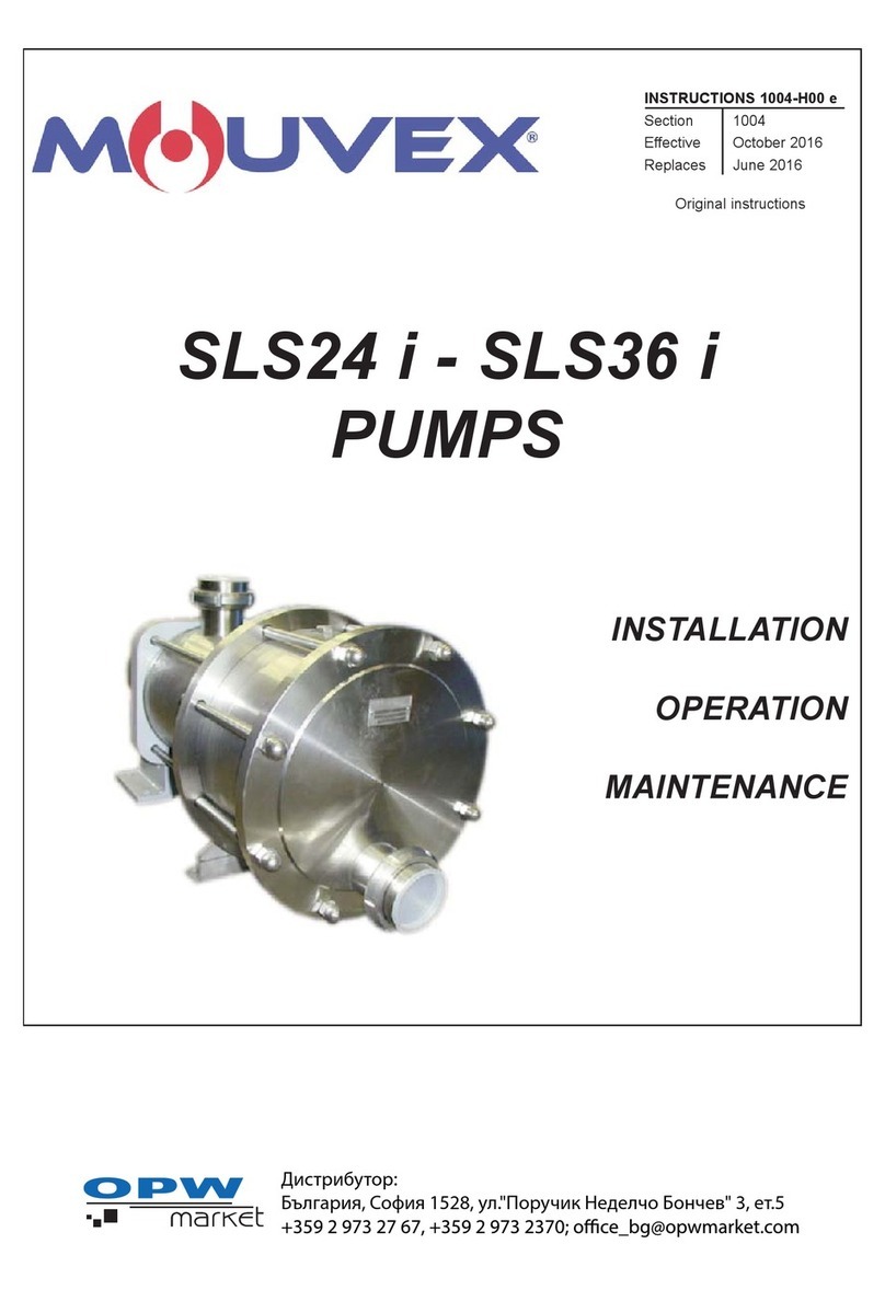
Mouvex
Mouvex SLS24 i Owner's manual
Popular Water Pump manuals by other brands
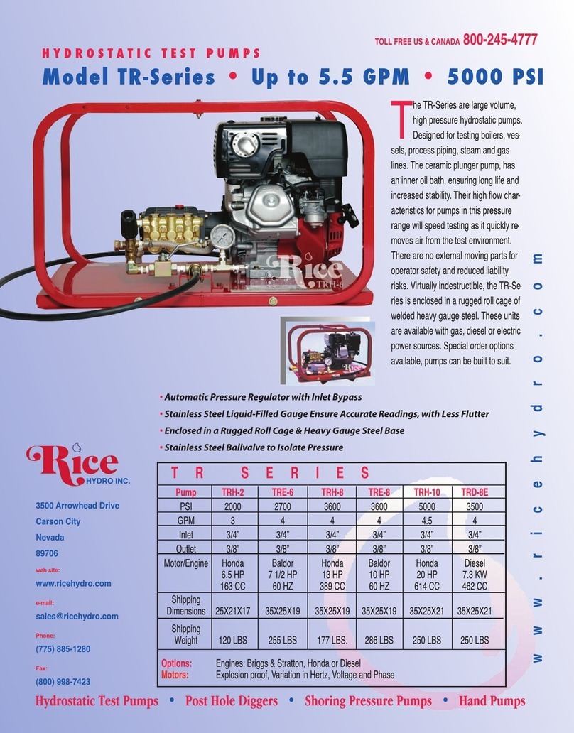
RICE HYDRO
RICE HYDRO TR Series quick start guide
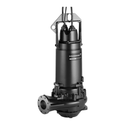
Grundfos
Grundfos S Installation and operating instructions
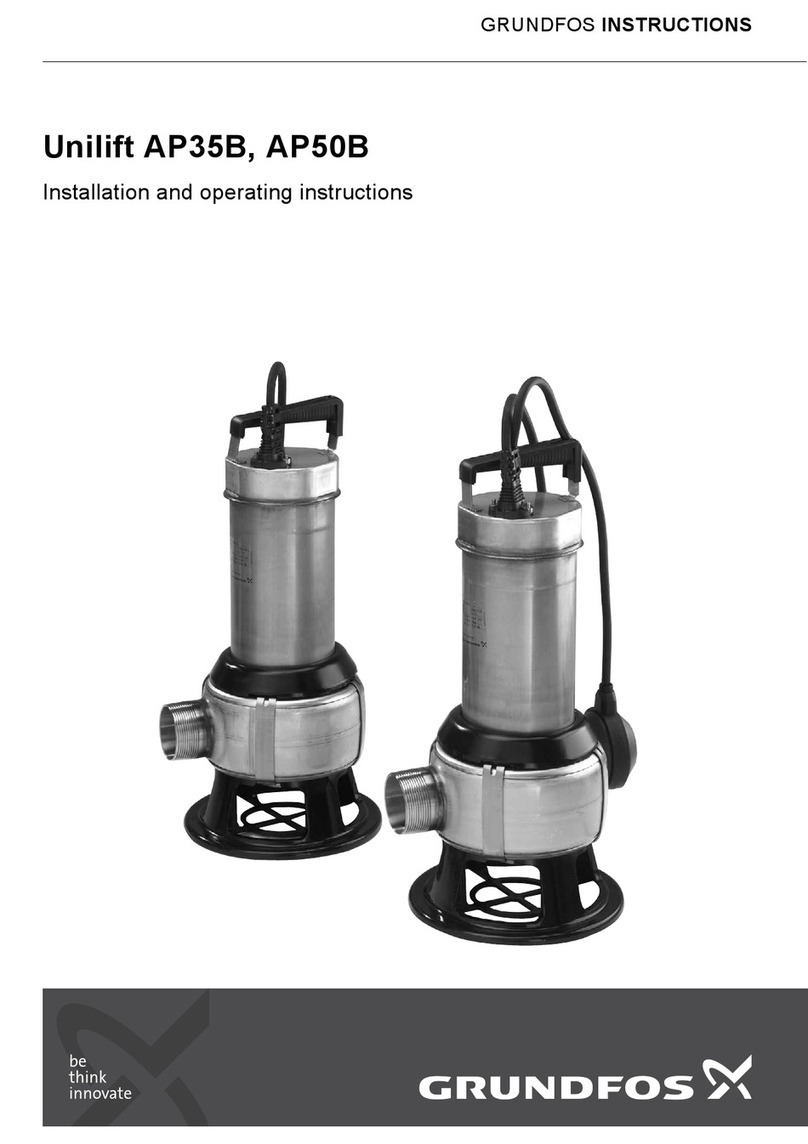
Grundfos
Grundfos UNILIFT AP35B Installation and operating instructions
Black Knight
Black Knight HCPRO 12 CFM Operation manual
Hozelock
Hozelock 3000 K7 manual
EINHELL
EINHELL 41.709.64 Original operating instructions
