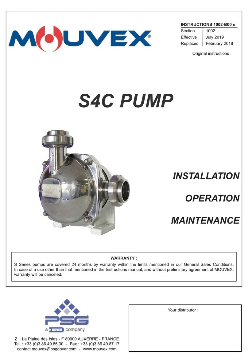
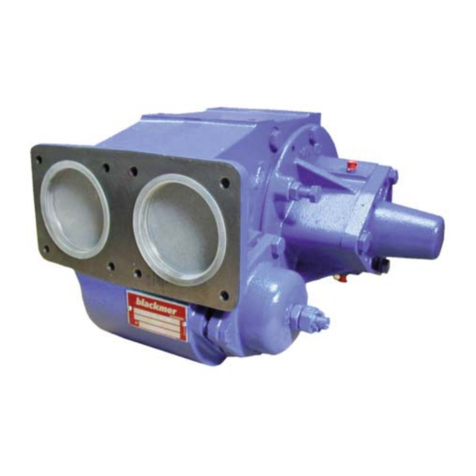
Mouvex CC8-40 Owner's manual

CC8-40 - CC8-50 - CC8-65
pumps
Constructions A & C
INSTRUCTIONS 1010-D00 e
Section 1010
Effective May 2020
Replaces March 2018
INSTALLATION
OPERATION
MAINTENANCE
Original instructions
Your distributor :
Z.I. La Plaine des Isles - F 89000 AUXERRE - FRANCE
Tel. : +33 (0)3.86.49.86.30 - Fax : +33 (0)3.86.49.87.17
contact.mouvex@psgdover.com - www.mouvex.com
WARRANTY :
CC8 Series pumps are covered 24 months by warranty within the limits mentioned in our General Sales Conditions.
In case of a use other than that mentioned in the Instructions manual, and without preliminary agreement of MOUVEX,
warranty will be canceled.

2/20
NT 1010-D00 05 20 CC8-40 - CC8-50 - CC8-65 A & C pumps e
NOTE :
The numbers after part names correspond to items in the
spare parts lists.
REMARKS :
CC8 pumps MUST be installed in systems designed by qualified
personnel. The installation MUST be in compliance with local stan-
dards, national regulations and rules of safety.
This manual is designed to permit installation and commis-
sioning of CC8 pumps and MUST accompany the pump.
Maintenance of CC8 pumps must ONLY be carried out by qualified
technicians. This maintenance must meet local and national stan-
dards as well as all safety regulations. Read this manual, including
all instructions and warnings, in full BEFORE any use of CC8
pumps.
Do not remove the warning and use label stickers that are found
on the CC8 pumps.
Definition of safety symbols
This is a SAFETY ALERT SYMBOL.
When you see this symbol on the product, or in the manual,
look for one of the following signal words and be alert to the
potential for personal injury, death or major property damage.
Warns of hazards that WILL cause serious personal injury,
death or major property damage.
Warns of hazards that CAN cause serious personal injury,
death or major property damage.
Warns of hazards that CAN cause personal injury or property
damage.
NOTICE
Indicates special instructions which are very important and
must be followed.
DANGER
WARNING
CAUTION
1. OPERATING LIMITS . . . . . . . . . . . . . . . . . . . . . . . . . . . . .3
2. OVERALL DIMENSIONS . . . . . . . . . . . . . . . . . . . . . . . . . .4
3. INSTALLATION . . . . . . . . . . . . . . . . . . . . . . . . . . . . . . . . .8
3.1 Choice of pump . . . . . . . . . . . . . . . . . . . . . . . . . . . . . . .8
3.2 Direction of rotation . . . . . . . . . . . . . . . . . . . . . . . . . . . .8
3.3 Pump protection . . . . . . . . . . . . . . . . . . . . . . . . . . . . . .8
3.4 Pipe diameter . . . . . . . . . . . . . . . . . . . . . . . . . . . . . . . .8
3.5 Piping assembly . . . . . . . . . . . . . . . . . . . . . . . . . . . . . .8
3.6 Bypass setting . . . . . . . . . . . . . . . . . . . . . . . . . . . . . . . .9
4. DIRECT DRIVE BY MOTOR . . . . . . . . . . . . . . . . . . . . . . .10
4.1 Installation of units . . . . . . . . . . . . . . . . . . . . . . . . . . .10
4.2 Alignment of motor/pump and reduction gearbox/pump
shafts . . . . . . . . . . . . . . . . . . . . . . . . . . . . . . . . . . . . .10
4.3 Electric motors . . . . . . . . . . . . . . . . . . . . . . . . . . . . . .11
4.4 Diesel engines drive . . . . . . . . . . . . . . . . . . . . . . . . . .11
5. DRIVE BY POWER TAKE OFF . . . . . . . . . . . . . . . . . . . . .11
6. USE . . . . . . . . . . . . . . . . . . . . . . . . . . . . . . . . . . . . . . . . .12
6.1 Pumping hot liquids . . . . . . . . . . . . . . . . . . . . . . . . . .12
6.2 Pump full of liquid when stopped . . . . . . . . . . . . . . . .12
6.3 Starting-up the pump . . . . . . . . . . . . . . . . . . . . . . . . .12
6.4 Running without liquid in the pump . . . . . . . . . . . . . . .12
6.5 Using of the pump with a valve closed on the
discharge line . . . . . . . . . . . . . . . . . . . . . . . . . . . . . . .12
6.6 Shutting down the pump . . . . . . . . . . . . . . . . . . . . . . .12
6.7 Protection from frost . . . . . . . . . . . . . . . . . . . . . . . . . .13
6.8 Restarting . . . . . . . . . . . . . . . . . . . . . . . . . . . . . . . . . .13
7. NECESSARY TOOLS . . . . . . . . . . . . . . . . . . . . . . . . . . . .14
8. DISMANTLING - REASSEMBLY . . . . . . . . . . . . . . . . . . .14
8.1 Dismantling on side opposite to drive system . . . . . .15
8.2 Dismantling on drive side . . . . . . . . . . . . . . . . . . . . . .15
8.3 Reassembly . . . . . . . . . . . . . . . . . . . . . . . . . . . . . . . .15
8.4 Assembly of flange for hydraulic trunk . . . . . . . . . . . .15
9. CHANGING THE VANES . . . . . . . . . . . . . . . . . . . . . . . . .16
10. CHANGING MONOBLOC SHAFT SEAL . . . . . . . . . . . . .16
11. BYPASS . . . . . . . . . . . . . . . . . . . . . . . . . . . . . . . . . . . .17
12. MAINTENANCE . . . . . . . . . . . . . . . . . . . . . . . . . . . . . . .17
12.1 Lubrication . . . . . . . . . . . . . . . . . . . . . . . . . . . . . . . .17
12.2 Inspection of the vanes . . . . . . . . . . . . . . . . . . . . . . .17
12.3 Cleaning the filter . . . . . . . . . . . . . . . . . . . . . . . . . . .17
13. TROUBLESHOOTING . . . . . . . . . . . . . . . . . . . . . . . . . .18
13.1 Abnormal noise . . . . . . . . . . . . . . . . . . . . . . . . . . . . .18
13.2 Leaking seal . . . . . . . . . . . . . . . . . . . . . . . . . . . . . . .18
13.3 Inadequate output . . . . . . . . . . . . . . . . . . . . . . . . . . .18
14. STORAGE . . . . . . . . . . . . . . . . . . . . . . . . . . . . . . . . . . .19
14.1 Short duration (≤ 1 month) . . . . . . . . . . . . . . . . . . . .19
14.2 Long duration (> 1 month) . . . . . . . . . . . . . . . . . . . .19
15. SCRAPPING . . . . . . . . . . . . . . . . . . . . . . . . . . . . . . . . .19
16. CERTIFICATE OF CONFORMITY . . . . . . . . . . . . . . . . .20
TABLE OF CONTENTS Page
TANK TRUCK PUMP
SAFETY, STORAGE, INSTALLATION AND MAINTENANCE INSTRUCTIONS
MODELS : CC8-40 - CC8-50 - CC8-65 A & C

3/20
NT 1010-D00 05 20 CC8-40 - CC8-50 - CC8-65 A & C pumps e
1. OPERATING LIMITS
The pumps CC8 are delivered with spring (4 or 8 bar) adjusted at 4 bar.
When requested, they can be delivered with a 8 bar spring adjusted at the maximum pressure of use.
Temperature range allowed : Construction A ..........-20°C to +80°C
Construction C..........-20°C to +170°C
Products authorised : Clean petroleum product
Other products: Contact us
Construction Speed range
(rpm)
Flow rate pression
(m3/h) Max
pressure
(bar)
Required power
(Kw)
CC8-40 CC8-50 CC8-65 CC8-40 CC8-50 CC8-65
Construction A
Viscosity < 40 cSt 450 ► 1200 48 - - 4 7,6 - -
450 ►750 28 35 44 8 7,8 10 13
450 ► 1000 40 50 65 4 6 6,5 8,5
Construction C
Viscosity < 400 cSt 450 ►750 31 36 44 8 9,7 11 13
Viscosity < 900 cSt 450 ►600 - - 35 6 - - 7,7

4/20
NT 1010-D00 05 20 CC8-40 - CC8-50 - CC8-65 A & C pumps e
2. OVERALL DIMENSIONS
Weight : 48 kg
CC8-40
CC8-50
EBypass adjustment
JEnd plate dismounting
V1 Drain/vacuum plug
V2 Drain/pressure plug
PPump plate
PA ATEX plate
SInserting M6 sensor - Thread size : 8 mm

5/20
NT 1010-D00 05 20 CC8-40 - CC8-50 - CC8-65 A & C pumps e
2. OVERALL DIMENSIONS (continued)
Weight : 57 kg
CC8-65
EBypass adjustment
JEnd plate dismounting
V1 Drain/vacuum plug
V2 Drain/pressure plug
PPump plate
PA ATEX plate
SInserting M6 sensor - Thread size : 8 mm

6/20
NT 1010-D00 05 20 CC8-40 - CC8-50 - CC8-65 A & C pumps e
2. OVERALL DIMENSIONS (continued)
$
[0
3
(
9
0
9
0
6
3$
[0
[0
VXU
[0
VXU
[0
Weight : 56 kg
CC8-40 - CC8-50
with SAE-A hydraulic motor
Hydraulic motor
Coupling hub provided
for hydraulic motor shaft Ø 25
(for other Ø consult us)
DETAIL A
DETAIL B
DETAIL B : Motor fixation
EBypass adjustment
V1 Drain/vacuum plug
V2 Drain/pressure plug
PPump plate
PA ATEX plate
SInserting M6 sensor - Thread size : 8 mm

7/20
NT 1010-D00 05 20 CC8-40 - CC8-50 - CC8-65 A & C pumps e
2. OVERALL DIMENSIONS (continued)
!>'
!>'
<
<
Weight : 67 kg
CC8-65
with SAE-A hydraulic motor
Hydraulic motor
Coupling hub provided
for hydraulic motor shaft Ø 25
(for other Ø consult us)
DETAIL A
DETAIL B
DETAIL B : Motor fixation
EBypass adjustment
V1 Drain/vacuum plug
V2 Drain/pressure plug
PPump plate
PA ATEX plate
SInserting M6 sensor - Thread size : 8 mm

8/20
NT 1010-D00 05 20 CC8-40 - CC8-50 - CC8-65 A & C pumps e
3.1 Choice of pump
To obtain the service expected from a MOUVEX pump,
regarding both performance and longevity, it is vital that
the type of pump, its speed and the materials used for its
construction are determined as a function of the pump
output, its installation and operating conditions.
You can contact our Technical Services at any time to
ask for the information you require.
3.2 Direction of rotation
The pump rotates in one direction only. This is indicated by
an arrow on the pump housing. However, the pump has
both of shaft-ends led out and must be driven through
one the other depending on the direction of rotation of the
power take-off.
Because the pump rotates in one direction only, the
positions of the suction and discharge ports are not be
reversed (see arrows on housing). The safety bypass
has not to be reversed.
3.3 Pump protection
It is essential to protect the pump against possible
foreign matter by connecting a filter to the suction pipe
(see Instructions 1011-G00 Filters PF).
3.4 Pipe diameter
In order to achieve the best usage conditions, it is impor-
tant to take the following recommendations into account
when it comes to pipe dimensions :
• The pipe diameter should be chosen as a function of
pipe length and the flow rate and viscosity of the pum-
ped liquid, so that any head loss remains within the per-
missible limits for the motor/pump unit. Therefore it is
difficult to give general and precise directions. However,
it is never a disadvantage to over-dimension pipe dia-
meters, especially for the section on the inlet side.
• In the case of thin liquids and the piping on the dischar-
ge side, one can generally allow a diameter equal to
that of the ports on the pump and a larger diameter for
the piping on the inlet side, if the value for the inlet
power of the pump is negative or especially high.
• In the case of viscous liquids, special care should be
given to choosing pipe diameters. In fact, the variation
in head loss is proportional to viscosity and inversely
proportional to the diameter as power of 3. A slight
reduction in the pipe diameter could have serious
consequences for the operating conditions of the pump.
Our Technical Services are always available to provide
you with precise data if you give them accurate informa-
tion or, better still, the installation plans.
3.5 Piping assembly
In order to achieve the best usage conditions, it is impor-
tant to take the following recommendations into account
when it comes to fitting pipes :
• The location of the pump in the transfer or recycling cir-
cuit should always be determined so as to reduce the
height and length of the piping as much as possible.
• Wherever possible, siphons and reverse slopes should
be avoided in the inlet piping.
• Particular care needs to be taken with the sealing on
the inlet side to prevent air entering.
• Pipe elbows must always have a large radius (more
than 3 times the diameter of the pipes) and must not be
mounted too close to the pump flanges (min. recom-
mended distance : 10 times the diameter of the pipes),
on both the inlet and discharge sides.
• The pipes are supported and aligned with the pump in
such a way as to avoid putting stress on the pump flan-
ges. Non-compliance with this instruction can lead to
deformation of pump parts, misalignment of bearings
and accelerated material wear, even causing parts to
break.
• For ease of adjustment and checking, it is recommen-
ded that pressure tapping ports for pressure
gauges/vacuum gauges be provided as close as pos-
sible to the pump’s inlet ports (preferably, at a distance
of less than 5 times the diameter of the piping).
• If the suction head is especially high or if you want to
prevent the pipes emptying at shutdown, you can
install a foot valve. It should have a large diameter so
as not to generate additional head loss.
• We recommend placing valves as close as possible to
the pump ports to avoid having to drain the entire sys-
tem each time maintenance is carried out. These val-
ves should have the same diameter as the pipes and
preferably by full bore models.
• All these steps should be taken to prevent foreign
bodies entering the pump (the use of a filter in the
pump inlet pipe is strongly recommended).
• Before installing new pipes or tanks, be sure to clean
them very carefully to remove any solder, rust, etc.
which could be carried along with the water and cause
excessive pump wear.
• The pipes should be designed to allow for thermal
expansion/contraction (the use of flexible hoses or
expansion loops is recommended).
• If the liquid may freeze or solidify, prepare for draining
the piping by installing drain taps at the low points and
air vents at the high points.
3. INSTALLATION

3.6 Bypass setting
The bypass must be set depending on the needs and
the limitations of the installation.
A preset can be operated for mechanical bypass, please
refer to the information below, but it has to be followed up
by a check-up on the installation.
Process :
• Loose the nut.
• Unscrew completely the pressure screw.
• Screw it clockwise depending on the values given below.
Please consider te accuracy is +/- 0,3 bar on the given
values.
• Tight the nut.
• Check on the installation the pump gives the right pres-
sure (using a manometer) with a closed valve on the
discharge line.
Pressure got (bar) :
CC8-40 - CC8-50
CC8-65
(1) Pressure limited to 8 bar, prohibited zone
Pressure screw
Pressure screw rotation Mechanical bypass
4 bar 8 bar
0 2,1 3,5
1 2,4 4,0
2 2,6 4,5
3 2,9 5,0
4 3,2 5,5
5 3,4 6,0
6 3,6 6,5
7 3,9 7,5
8 4,2 8,0
9 4,4 -
Pressure screw rotation Mechanical bypass
4 bar 8 bar
0 2,3 4,0
1 2,6 4,5
2 2,7 5,0
3 2,8 5,5
4 3,3 6,0
5 3,6 7,0
6 3,9 7,5
7 4,2 8,0
8 4,4 8,5 (1)
9 4,6 9,5 (1)
9/20
NT 1010-D00 05 20 CC8-40 - CC8-50 - CC8-65 A & C pumps e
3. INSTALLATION (continued)

4.1 Installation of units
The correct seating of the pump is vital for its efficient ope-
ration and its longevity. The base must be flat, level and
sufficiently resistant to absorb the stresses caused by the
motor-driven pump without deformation (if it is made of
concrete, it must comply with standard BAEL 91).
In the case where the unit is fastened by anchor lugs or
bolts, it must be carefully wedged to prevent any defor-
mation of the chassis when tightening the bolts.
Deformation of the chassis will cause stress prejudicial
to the pump and the drive device and put the coupling
out of true alignment, thereby causing vibrations, noise
and premature wear. Care must be taken so that the
chassis is clear of the ground, apart from the base pla-
tes.
If the chassis is a one-piece unit in doubled plate, it is
recommended that a horizontal clearance of about 50
cm be left between one section of the chassis and the
other to allow access for fastening the nuts on the pump,
reduction gearbox and motor. In all cases, the clearance
around the motor-driven pump should all room for
demounting the pump (for distances, refer to the dimen-
sion drawing at the start of the notice).
The chassis is equipped with a ground connection that
must be used to protect people and equipment.
4.2 Alignment of motor/pump and reduction
gearbox/pump shafts
The motor and pump shafts are accurately aligned at the
factory before dispatch, but they should be checked
carefully when received at the site and realigned if
necessary. To align the coupling and the shaft, use a
straight-edge to check the concentricity and thickness
gauges for the angular misalignment.
The 3 figures below show the procedure in detail and the
admissible deviations :
Controlling the alignment at each stage of the installation
is important to be sure that none of the following procedu-
res has generated stresses on the unit or the pump :
• after fastening on the foundations.
• after fastening the pipes.
• after the pump has been operated at the normal
operating temperature.
REMINDER :
You cannot rely on the coupling to compensate for mis-
alignment.
NEVER START A UNIT IF THE COUPLING ALIGNMENT IS
INCORRECT. THIS WILL RENDER OUR WARRANTY INVALID.
WARNING
OPERATION WITHOUT THE SHAFT
PROTECTOR CAN CAUSE SERIOUS
PERSONAL INJURY, MAJOR PROPER-
TY DAMAGE OR DEATH.
Do not operate
without guard
in place.
WARNING
DISCONNECT THE ELECTRICITY
SUPPLY BEFORE ANY MAINTENAN-
CE OPERATION.
Dangerous voltage.
Can cause
injury and death.
WARNING
BE CAREFUL WITH THE WEIGHT OF
THE PARTS WHEN THEY ARE BEING
REMOVED.
The weight ot the parts
can be dangerous and may
provoke bodily injuries
or material damages.
Carry out the control at four points :
at the top ‐ at the bottom ‐ left ‐ right
Correct
Bad alignment
Angular fault
(maximum : 1°)
10/20
NT 1010-D00 05 20 CC8-40 - CC8-50 - CC8-65 A & C pumps e
4. DIRECT DRIVE BY MOTOR

4.3 Electric motors
Check that the supply voltage matches the indications
on the motor rating plate.
Comply with the wiring diagram, make sure the wires are
rated for the power and take care with the contacts,
which must be thoroughly tightened. The motors must
be protected by appropriate circuit breakers and fuses.
Connect the regulatory ground connections.
Check the direction of rotation.
This check should be done with no liquid being pumped,
and both the inlet and discharge circuits vented to avoid
generating unexpected pressure (on the inlet side, for
example). This will avoid damaging either the pump or
the system.
Start the pump empty to check that the connections are
good and that the direction of rotation corresponds to the
system intake and discharge directions. If it is necessary
to reverse the direction of rotation, follow the instructions
below :
Three-phase motor : switch any 2 current input wires.
Bi-phase motor : switch two same phase wires.
Single-phase motor : follow the instructions on the notice
supplied with the motor.
4.4 Diesel engines drive
Do not forget that these engines are not reversible. It is
therefore vital to carefully check the inlet and outlet sides
of the pump before connecting the pump unit to the piping.
The use of diesel engines drive is now well known.
Nevertheless, we strongly recommend that you carefully
read the technical manuals concerning them.
WARNING
OPERATION WITHOUT THE SHAFT
PROTECTOR CAN CAUSE SERIOUS
PERSONAL INJURY, MAJOR PROPER-
TY DAMAGE OR DEATH.
Do not operate
without guard
in place.
WARNING
DISCONNECT THE ELECTRICITY
SUPPLY BEFORE ANY MAINTENAN-
CE OPERATION.
Dangerous voltage.
Can cause
injury and death.
WARNING
TAKE ALL NECESSARY MEASURES
TO RENDER ANY START-UP, EVEN
ACCIDENTAL, OF THE PUMP DURING
THE WORK IMPOSSIBLE.
Any unforeseen start-up
can cause serious
injuries or important
material damages.
WARNING
PUMPS OPERATING AGAINST A CLO-
SED VALVE CAN CAUSE SYSTEM
FAILURE, PERSONAL INJURY AND
PROPERTY DAMAGE.
Hazardous pressure
can cause
personal injury
or property damage.
CAUTION
THE SURFACES OF THE PUMP CAN
BE AT A TEMPERATURE LIABLE TO
CAUSE INJURY OR SEVERE DAMAGE.
Excessive temperature-
can cause injury
or severe damage.
11/20
NT 1010-D00 05 20 CC8-40 - CC8-50 - CC8-65 A & C pumps e
4. DIRECT DRIVE BY MOTOR (continued)
Refer to Instructions NT 1010-B00 CC8 CC10 CC20 PUMPS
DRIVEN BY POWER TAKE OFF.
5. DRIVE BY POWER TAKE OFF

12/20
NT 1010-D00 05 20 CC8-40 - CC8-50 - CC8-65 A & C pumps e
6. USE
The operator should remain nearby the equipment through-
out the use to ensure the proper functioning of the system.
6.1 Pumping hot liquids
When pumping hot liquids, make your you retighten
screws and bolts after starting for the first time in order
to compensate for contraction.
6.2 Pump full of liquid when stopped
If the pump circuit is to be located between valves and/or
a non-return valve, you need to take account of the
variations in temperature that can lead to contraction of
the liquid in the circuit. In this case, you need to provide
some means of compensating for the contraction. A dis-
charge valve may be sufficient. The opening pressure
for this valve should be compatible with the permitted
pressure for the other components in the circuit.
It is also advisable to fit a discharge device to allow the
circuit to be completely emptied for any maintenance work.
In the case of liquids containing particles settling on
shut-down, it is necessary to make sure the consistency
of the deposit will not impede restarting the pump.
6.3 Starting-up the pump
Before starting the pump, make sure that the following
conditions are met :
• The circuit should be in one of its pumping configu-
rations, with the appropriate valves open, especially
on the intake side.
• For products requiring heating, they must be brought
to their pumping temperature before starting the
pump.
6.4 Running without liquid in the pump
MOUVEX CC8 pumps can run without liquid in the pump
for 5 minutes without causing damage, in particular during
pump priming.
6.5 Using of the pump with a valve closed on
the discharge line
The using of the pump with a valve closed on the dis-
charge line implies the liquid is not renewed which gene-
rates a heating up. In consequence, that operating way
must not exceed 3 minutes.
6.6 Shutting down the pump
When shutting down the pump, we recommend waiting
for it to stop completely before closing the valves, espe-
cially the inlet valve.
WARNING
FAILURE TO INSTALL ADEQUATELY
SIZED PRESSURE RELIEF VALVE(S)
CAN CAUSE PROPERTY DAMAGE,
PERSONAL INJURY OR DEATH.
Hazardous pressure
can cause
personal injury
or property damage.
CAUTION
THE SURFACES OF THE PUMP CAN
BE AT A TEMPERATURE LIABLE TO
CAUSE INJURY OR SEVERE DAMAGE.
Excessive temperature-
can cause injury
or severe damage.
WARNING
IF PUMPING HAZARDOUS OR TOXIC
FLUIDS, THE SYSTEM MUST BE FLUS-
HED PRIOR TO PERFORMING ANY
SERVICE OPERATION.
Toxic or hazardous
fluids can cause
serious injury.
WARNING
FAILURE TO RELIEVE SYSTEM
PRESSURE PRIOR TO PERFORMING
PUMP SERVICE OR MAINTENANCE
CAN CAUSE PERSONAL INJURY OR
PROPERTY DAMAGE.
Hazardous pressure
can cause
personal injury
or property damage.
WARNING
OPERATION WITHOUT THE SHAFT
PROTECTOR CAN CAUSE SERIOUS
PERSONAL INJURY, MAJOR PROPER-
TY DAMAGE OR DEATH.
Do not operate
without guard
in place.

13/20
NT 1010-D00 05 20 CC8-40 - CC8-50 - CC8-65 A & C pumps e
6.7 Protection from frost
If there is a risk of frost with the product contained in
the pump, it is necessary to drain the body after each
use as follows :
Step 1 :
• Check there is no valve closed on the discharge side
as well potential counter pressure due to a check
valve or liquid remaining inside a vertical pipe.
• Rotate the pump.
• Create an air entering on the suction side during 30
seconds.
• Stop the pump and make sure no liquid is coming
back > pump has to be closed.
Step 2 :
• Defect or in complement, drain by the bottom plug.
6.8 Restarting
Follow the standard start-up procedure for the pump/
motor-driven pump, as well as the instructions below.
Turn the pump by hand to make sure the parts move
freely.
Remove the bypass and inspect the parts and make
sure they move freely.
Drain plug
6. USE (continued)

14/20
NT 1010-D00 05 20 CC8-40 - CC8-50 - CC8-65 A & C pumps e
• Flat wrenches 13 - 17 - 22
• Tube wrench 17
• Circlip opening pliers
• Screwdriver
Makeup torques :
• M10 ...........47 Nm
• M 8 ............23 Nm
• M 6 ............10 Nm
7. NECESSARY TOOLS
Before any dismantling, make sure that the pump has been drained and take all the necessary precautions to prevent it from star-
ting up. The pump must not start up, even accidentally.
WARNING
DISCONNECTING THE FLUID OR
PRESSURE CONTAINMENT COMPO-
NENTS DURING PUMP OPERATION
CAN CAUSE SERIOUS PERSONAL
INJURY, DEATH OR MAJOR PROPERTY
DAMAGE.
Hazardous pressure
can cause
personal injury
or property damage.
WARNING
IF PUMPING HAZARDOUS OR TOXIC
FLUIDS, THE SYSTEM MUST BE FLUS-
HED PRIOR TO PERFORMING ANY
SERVICE OPERATION.
Hazardous or toxic
fluids can cause
serious injury.
CAUTION
THE PUMP LUBRICANT IS VERY SLIPPE-
RY AND MAY CAUSE SERIOUS INJURY.
ANY SPILLS MUST BE CLEANED UP.
Slippery lubricant.
Spills should be
cleaned up.
WARNING
FAILURE TO RELEASE ALL SYSTEM AIR
AND WHEN EQUIPPED, HYDRAULIC
PRESSURE, CAN CAUSE PROPERTY
DAMAGE, PERSONAL INJURY OR DEATH.
Hazardous pressure
can cause
personal injury
or property damage.
WARNING
DISCONNECT THE ELECTRICITY
SUPPLY BEFORE ANY MAINTENAN-
CE OPERATION.
Dangerous voltage.
Can cause
injury and death.
CAUTION
THE SURFACES OF THE PUMP CAN
BE AT A TEMPERATURE LIABLE TO
CAUSE INJURY OR SEVERE DAMAGE.
Excessive temperature-
can cause injury
or severe damage.
WARNING
BE CAREFUL WITH THE WEIGHT OF
THE PARTS WHEN THEY ARE BEING
REMOVED.
The weight ot the parts
can be dangerous and may
provoke bodily injuries
or material damages.
WARNING
TAKE ALL NECESSARY MEASURES
TO RENDER ANY START-UP, EVEN
ACCIDENTAL, OF THE PUMP DURING
THE WORK IMPOSSIBLE.
Any unforeseen start-up
can cause serious
injuries or important
material damages.
8. DISMANTLING - REASSEMBLY

15/20
NT 1010-D00 05 20 CC8-40 - CC8-50 - CC8-65 A & C pumps e
8. DISMANTLING - REASSEMBLY (continued)
8.1 Dismantling on side opposite to drive system
Unscrew the screws 723, and remove the cover 712 and
the seal 714.
Remove circlip 537.
Carefully clean the shaft end (remove any trace of paint,
oxidation, burrs...).
Unscrew the 4 screws 410.
Unscrew the 4 screws 411 fitted with their nut 412 and
place them in the 2 tapped holes T.
Screw up the 2 screws at the same time so that the end-
plate is gradually released along the centre line.
When the end-plate is free on the shaft, hold it by hand
supporting it.
8.2 Dismantling on drive side
Uncouple the pump by removing the coupling.
Remove the key 508 and clean the end shaft. Then pro-
ceed in the same way as when dismounting on the other
side. On CC8-40 and CC8-50 pumps, it is necessary to
push cover 705 slightly a side to avoid damaging O-ring
707 on key.
Unscrew the screws 723, remove the cover 705 with its
seal 714 taking care not damaging seal 707.
Remove the circlip 537.
Operate then in a identical way in § DISMANTLING ON
SIDE OPPOSITE TO DRIVE SYSTEM.
8.3 Reassembly
When putting the end-plate back into place, take care to
have the shaft seal drive lugs facing the notches on
rotor.
Replace the cover 712 or 705 on the end plate 401 with
screws 723.
Lubricate the shaft 501 slightly.
Make sure that the end-plate seal 403 is correctly posi-
tioned, check it and change it if necessary.
Position the end plate 401 on the shaft and approach it
as far as possible by hand.
Finish fitting the end-plate, screwing the 2 nuts 412 gra-
dually on to the 2 screws 411.
Make sure that end-plate is centred while screwing.
When the end-plate is in place, remove the screws 411
and their nuts 412 and screw them up in the 2 bosses
taking care to position one of the drainage port L pointing
down.
Replace the screws 410.
Remove the cover 712 or 705.
Replace the circlip 537.
Replace the cover 705 with its seal 707 after check
condition of seal.
Free the shaft line by a light blow of mallet on its extremity
and make sure that the pump rotates freely when turned
by hand.
8.4 Assembly of flange for hydraulic trunk
Refer to Instructions NT 1010-K00 ASSEMBLY OF FLANGE
FOR HYDRAULIC TRUNK ON PUMP CC8 CC10.

16/20
NT 1010-D00 05 20 CC8-40 - CC8-50 - CC8-65 A & C pumps e
9. CHANGING THE VANES
Dismantling
Open the pump and remove the end-plate on its machined
side taking care not to damage the shaft seal drive lugs.
Remove parts.
Remove shaft seal by inserting fingers in shaft seal
center hole.
Reassembly
IMPORTANT
Lubricate the bore which takes the roller bea-
rings.
Make sure that the seals 605, 613 and the shaft seal
are in good condition. Change them if necessary.
Place the seal 605 in the end plate 401.
Make sure that the seal 613 is correctly positioned in
the shaft seal 630.
Refit the shaft seal 630 (a new one if necessary), in the
end plate 401, supported on the seal 605.
Place the protection ring 733 so as to be supported on
the shaft seal 630.
Place a bearing 703 supported on the protection ring 733.
Position the spacer 734 with its aperture opposite a
grease nipple 708 (if present).
Place the second bearing 703 so it is supported on the
spacer 734.
Refit the end plate (see § REASSEMBLY OF THE PUMP).
10. CHANGING MONOBLOC SHAFT SEAL
Open the pump on one side or the other.
Remove the vanes 317.
Check for wear (see § MAINTENANCE).
If vane wear is abnormal, check surface condition of body
and of end-plate faces.
Refit the vanes (new if necessary) respecting the direction of
assembly.
Reassemble the pump and check that it rotates freely when
turned by hand.

17/20
NT 1010-D00 05 20 CC8-40 - CC8-50 - CC8-65 A & C pumps e
Dismantling
Set bypass at minimal pressure by unscrewing the
lock-nut 835 taking care to count the number of rota-
tions so as to be able to reset bypass at initial pressure
setting.
Unscrew the 3 screws 856 of the bypass cap.
Remove spring 824.
Remove the valve 823 by pulling its cylindrical section
with the fingers.
Check condition of bypass.
Reassembly
Clean all parts before reassembly.
Reassemble in reverse order of dismantling.
Set bypass at initial pressure setting by tightening nut
with the same number of rotations as counted during
dismounting.
11. BYPASS
12.1 Lubrication
Pumps CC8-40A ; CC8-50A ; CC8-65C :
• Grease to use : good quality ball bearing grease.
In case of pumps operated higher than 100°C, a high
point of drop grease has to be selected.
• Fréquency : every 500 hours or one time per year.
• Injected volume : the usage of a pneumatic grease pump
is forbidden because of the risk to damage the mecha-
nical seals. The grease has to be added with a manual
pump, 2 blows on an only one grease nipple of every
pump end.
Pump CC8-65A :
Ball bearing are lubricated for life and don’t require any
grease adding.
12.2 Inspection of the vanes
12.3 Cleaning the filter
The pump should always be protected against possible
foreign matter by means of a filter connected into the
suction pipe.
Check the cleanliness of the filter mesh from time to time
as a.partly clogged filter could starve the pump and reduce
its output.
To clean the filter, remove the meshes and clean them
carefully. Before refitting them, drain the filter by removing
the drain plug, then rinse it thoroughly.
Pump CC8-40 CC8-50 CC8-65
Original height h 35 35 38
Change when h < to 30,5 32,5 35,5
12. MAINTENANCE

18/20
NT 1010-D00 05 20 CC8-40 - CC8-50 - CC8-65 A & C pumps e
13. TROUBLESHOOTING
13.1 Abnormal noise
Main causes :
• Excessive suction vacuum, due to :
- a pipe, accessories (valves, filter...) which are either
clogged or of insufficient diameter,
- excessive suction head (e.g. during liquid transfer
operations),
- a viscosity or vapour tension too high for the system
to cope with (e.g. when changing the product to be
pumped).
• Overly high rotation speed for the liquid being pumped.
• Pump damaged
- as a result of binding due to :
• an excessively high rotation speed,
• failure to release the drive when pumping is ended,
• sudden engagement of the drive,
• an unduly high pulling force on the shaft, leading to
a damaged ball-bearing and shaft.
- as a result of foreign matter, due to :
• the absence of a filter or inefficient cleaning,
• the absence of a basket (faîlure to replace it after
cleaning),
• solder or rust particles remaining in the pipe bet-
ween the filter and the pump.
• Bypass valve hammer on its seat due to incorrect
adjustment of the spring’s tension.
13.2 Leaking seal
Main causes :
- Abnormal pulling force on the shaft, leading to a dama-
ged bearing and seal,
- Displacement of the shaft when mounting an unduly
tight coupling making the seal unserviceable,
- Seal damage caused by pumping an agressive product,
- Ball-bearing lubricated excessively or at unduly high
pressure.
13.3 Inadequate output
Main causes :
- Excessive suction vacuum (see § Abnormal noise -
Excessive suction vacuum),
- Bypass setting too low,
- Air leaking in at suction end,
- Discharge pipe diameter too small,
- Speed of rotation too low,
- Bypass valve not closing properly due to foreign mat-
ters on valve seat or because the valve lifting wheel (in
the case of pumps fitted with one) has not been retur-
ned to its initial position after use,
- Pump damaged (see § Abnormal noise - Pump damaged
due to passage of foreign matter).
CAUTION :
OBSERVE ALL SAFETY WARNINGS CONTAINED IN THIS MANUAL.

19/20
NT 1010-D00 05 20 CC8-40 - CC8-50 - CC8-65 A & C pumps e
14.1 Short duration (≤ 1 month)
MOUVEX pumps and motor-driven pumps are well lubri-
cated when delivered to protect the internal parts during
brief storage in a building where :
• the temperature remains between 10°C and 50°C.
• the relative humidity does not exceed 60%.
• exposure to vibration is limited (maximum movement :
0,05 mm).
• pump is stored in an area sheltered from bad weather
and sun.
14.2 Long duration (> 1 month)
We recommend the following procedure for longer periods
of storage :
The recommendations from the manufacturer should be
followed if the pump is stored with its gear motor.
Pump ports should be filled with a non-corrosive liquid
that it compatible with the pump components in order to
prevent corrosion.
Unpainted external surfaces of the pump (e.g. shafts,
couplings, etc.) should be covered in some form of anti-
corrosion protection.
The bearing should be greased. If the pump is to be stored
for more than three years, the grease should be replaced
every three years to prevent it degrading.
The best storage conditions are inside a building that
meets the conditions set out above.
If inside storage is not possible, the materials should be
covered to prevent direct exposure to sun and bad wea-
ther. This protection should also prevent condensation.
It is recommended to turn the pump by hand every two
months to distribute the lubricant around the interior.
Items should then be placed where there is no risk of
damage if they are moved slightly by vibrations.
WARNING
IF PUMPING HAZARDOUS OR TOXIC
FLUIDS, THE SYSTEM MUST BE FLUS-
HED PRIOR TO PERFORMING ANY
SERVICE OPERATION.
Toxic or hazardous
fluids can cause
serious injury.
14. STORAGE
The pump must be scrapped in compliance with the regulations
in force.
During this operation, particular care must be paid to the drai-
nage stages of the pump (pumped product).
15. SCRAPPING

20/20
NT 1010-D00 05 20 CC8-40 - CC8-50 - CC8-65 A & C pumps e
Est conforme aux dispositions suivantes :
Directive « MACHINES » 2006/42/CE et aux législations nationales la
transposant, portant sur les dispositifs de sécurité liés aux risques
mécaniques et électriques applicables aux machines tournantes.
NF EN 809:2009 NF EN 1672-2:2009 NF EN ISO 13857:2008
NF EN 12162:2009
Directive « ATEX » 2014/34/UE du 26 février 2014 et aux législations
nationales la transposant, portant sur les appareils destinés à être utilisés
en atmosphères explosibles. Conformité obtenue par application des
normes :
NF EN 1127-1:1997 NF EN 13463-1:2009 NF EN 13463-5:2009
Certification ATEX délivrée par INERIS*, Organisme Certificateur, et portant
le marquage suivant : (C)
L’équipement désigné ci-dessus doit impérativement respecter les
conditions d’utilisation ATEX décrites dans nos notices d’instruction. Il doit
être employé conformément à l’utilisation qui en a été prévue de par sa
conception et sa fabrication, et conformément aux normes en vigueur.
Nous, soussignés, déclarons que l’équipement concerné est conforme aux
Directives listées ci-dessus et aux normes applicables s’y rapportant.
Is in conformity with the provis
i
ons of the following D
i
rective:
« MACHINES » Directive 2006/42/EEC as transposed by the national
legislation, concerning safety equipments and arrangements relative to
mechanical and electric risks applicable to rotative machines.
NF EN 809:2009 NF EN 1672-2:2009 NF EN ISO 13857:2008
NF EN 12162:2009
« ATEX » Directive 2014/34/EU (26 Feb. 2014) as transposed by the
national legislation, concerning equipment intended to be used in explosive
atmospheres. Conformity obtained by application of the standards :
NF EN 1127-1:1997 NF EN 13463-1:2009 NF EN 13463-5:2009
ATEX Certification delivered by INERIS*, Notified Body, and with the
following marking: (C)
The equipment indicated above must imperatively comply with the ATEX
conditions of use described in our Instruction book. It must be used
according to the foreseen use by its design and its manufacturing, and
according to the current standards.
We, undersigned, declare that the concerned equipment is in conformity
with the Directives listed above and in the applicable standards in force.
den Bestimmungen der nachstehenden Richtlinien en
t
spricht:
„Maschinen-Richtlinie“ 2006/42/EEC wie umgesetzt im nationalen Recht
hinsichtlich der Ausrüstungssicherheit und Sicherheitsvorkehrungen bezogen
auf mechanische und elektrische Risiken, die für rotierende Maschinen
gelten.
NF EN 809:2009 NF EN 1672-2:2009 NF EN ISO 13857:2008
NF EN 12162:2009
„ATEX“ Richtlinie 2014/34/EU (26. Feb. 2014) wie umgesetzt im
nationalen Recht in Bezug auf Ausrüstungen für den Einsatz in
explosionsgefährdeter Atmosphäre. Die Konformität hat Geltung durch
Anwendung folgender Normen:
NF EN 1127-1:1997 NF EN 13463-1:2009 NF EN 13463-5:2009
Die ATEX-Zertifizierung wurde von der benannten Stelle INERIS* erteilt, und
mit folgender Kennzeichnung: (C)
Oben stehend bezeichnete Ausrüstung muss unbedingt den in unseren
Betriebsanleitungen beschriebenen ATEX Anwendungs-bedingungen
entsprechen. Sie ist entsprechend dem durch Konstruktion und Fabrikation
vorgesehenen Verwendungszweck und entsprechend den geltenden Normen
einzusetzen.
Die Unterzeichner erklären, dass die bezeichnete Ausrüstung den oben
aufgeführten Richtlinien und den diesbezüglich geltenden Normen entspricht.
DECLARATION UE DE CONFORMITE
EU CERTIFICATE OF CONFORMITY – EU KONFORMITÄTSERKLÄRUNG
MOUVEX sas, ZI La Plaine des Isles – 2 Rue des Caillottes – 89000 Auxerre France, déclare que l’équipement suivant / declares the following equipment / erklärt, dass folgende Ausrüstung:
Modèle : N° de série : (A) Répondant aux spécifications indiquées dans l’ARC N° : (B)
Designation / Bezeichnung Serial N° / Serien Nr According to the specifications recorded in the acknowledgment of order N°:
Entsprechend den Spezifikationen aus AB-Nr :
Pour la Sté MOUVEX sas, fait à Auxerre le :
For Mouvex sas company – Date :
Fur die Fa Mouvex sas - Datum :
Responsable Qualité Clients
Customer
Q
ualit
y
Mana
g
er
/
Q
ualitätsbeau
f
tra
g
te
r
II __ G ____ II __ – T __ Temp Max produit pompé / Max Temp Flow / Max. T° Medium = _____ °C (X = voir notice / see IOM / siehe Handbuch)
Configuration : Pompe / Compresseur arbre nu Groupe de pompage / de compression
Konfiguration (Pump / Compressor « bare-shaft ») (Pumping Unit / Compressor Unit)
(Pumpe / Kompressor, freies Wellenende (Pumpen- / Kompressoraggregat)
Type / Geräteart :
Pompe à mvt excentré (Eccentric Disc Pump / Ringkolbenpumpe)Pompe à lobes (Lobes Pump / Drehkolbenpumpe)
Pompe péristaltique (Peristaltic Pump / Schlauchpumpe) Pompe à palettes (Vanes Pump / Flügelzellenpumpe)
Pompe centrifuge (Centrifugal Pump / Kreiselpumpe)Autre pompe (Other Pump / Andere Pumpe)
Compresseur à Vis (Screws compressor / Schraubenverdichter)
Compresseur à palettes (Vanes compressor / Flügelzellenverdichter)
Refroidisseur H
y
drauli
q
ue (H
y
draulic oil cooler / H
y
draulikkühler
)
CTRL.D025 – rév.04 du 25/05/2016 – Déclaration de conformité CE-Atex
* (INERIS
–
Parc Techno Atala
–
60550 Ver
n
eui
l
-
e
n
-
Halatte
–
France
)
.Pa
g
e 1/2
16. CERTIFICATE OF CONFORMITY
This manual suits for next models
2
Table of contents
Other Mouvex Water Pump manuals
Mouvex
Mouvex C24 i Owner's manual

Mouvex
Mouvex AK Series Guide
Mouvex
Mouvex SLS24 i Owner's manual

Mouvex
Mouvex SLC24 i Owner's manual
Mouvex
Mouvex SLP25 i Series User manual
Mouvex
Mouvex SLC1 Owner's manual
Mouvex
Mouvex SLS12 i Owner's manual

Mouvex
Mouvex SLS4 i User manual
Mouvex
Mouvex CC8-80 F Owner's manual
Mouvex
Mouvex C12 A Owner's manual
Popular Water Pump manuals by other brands

Oase
Oase AquaMax Eco Twin 20000 operating instructions

KSB
KSB MEGAFLOW 50-160 Operating instructions manual
Silicon Solar
Silicon Solar AquaJet-Pro-PUMP1224 user manual
Walrus
Walrus TQ1500 Replacing
ULTIMATE SPEED
ULTIMATE SPEED KH 4256 Original operating instructions

Garland
Garland GEISER 281 G instruction manual
