MOXTEK X-ray Sources MOX-HPC150 Max User manual

MOXTEK
®TUB-MAN-1020 Rev C
Subject to technical change without notice
MOX-HPC150 Max
Operation Manual
Table of Contents
• Introduction
• X-ray Source Characteristics
• Tube Current and Power Operational Range
• Initial Inspection
• Handling
• Mechanical
• Tube Setup and Operating Instructions
• Operating Precautions - Warnings
1
2
2
2
2
3
4
7
1
X-ray
Sources
Introduction
Moxtek HPC 150W 75kV X-ray tubes are designed to be used in XRF
and imaging applications. The tube is designed to be air-cooled and
the cooling can be adapted to meet specic needs. The push/pull fan
conguration makes it easy to direct the warm air outward. For XRF
applications the cone is designed for a vacuum seal at its base. The HPC
tube incorporates radiation shielding.
Figure 1 - The Moxtek HPC150

MOXTEK
®TUB-MAN-1020 Rev C
Subject to technical change without notice
2
X-ray Source Characteristics
Initial Inspection
X-ray Tube Characteristics
Tube Type: Metal-ceramic
Operating Temp: +10° C to +50° C*
Storage Temp: -20° C to +60° C
Cooling: Filtered Air (three n options*)
Weight: 2.5kg* (w/o cable)
Available Targets: Tungsten, Molybdenum
Fan Operating Voltage: 12V or 24V*
Connector Type: CA-11 typical (75kV max)
HV Polarity: Grounded anode
High Voltage: 10kV to 60kV
Max Beam Current: 5mA (long life performance)
Maximum Power: 150 Watts
Window: Beryllium
0.0
1.0
2.0
3.0
4.0
5.0
6.0
7.0
8.0
9.0
10.0
0
25
50
75
100
125
150
175
200
0 10 20 30 40 50 60 70 80
mA
MOX-
Maximum Power Maximum mA
Tube Current and Power Operational Range
When a Mox HPC tube is received, it should be unpacked and inspected as soon as possible. Caution: Do not lift or carry the
tube by the high voltage cable. Inspect the tube assembly for any damage. The Beryllium should not have any cracks or holes.
The copper heat sinks should be tightly joined (See Figure 3). The fans should be free of chips or cracks and have the wires
properly attached. Inspect the high voltage cable for proper tight and solid strain relief at the base of the tube. In the unlikely
event that a tube has been damaged during shipping, note the damage and contact MOXTEK immediately. The serial number is
Figure 2 - Voltage vs. Current and Power
*Fin and fan congurations can be optimized for the system and application
Damaged,
not properly joined
Properly joined,
no gap
Figure 3 - Heat sinks joint inspection

MOXTEK
®TUB-MAN-1020 Rev C
Subject to technical change without notice
3
Cone Angle 45°
Center Line to
Central Ray Angle 52.5°
Mechanical
Mounting
The MoxHPC may be mounted by the two ANSI ¼-20 UNC threaded holes on the tube end of the heat sinks. Alternately, M5 or
#10 bolts can be used in the thru-holes to capture the assembly.
Figure 4 - MoxHPC threaded hole mounts
Handling
Care should be taken when handling the tube. Do not drop or strike the tube on any surface. Care must be taken to not damage
the beryllium window or high voltage cable. Support the weight of the tube when lifting or carrying.
Caution: Do not lift or carry the tube by the high voltage cable.
Cooling
The MoxHPC utilizes a fan and heat sink for a combination of forced-air convection and conduction cooling. The tube should be
operated in an environment that allows convection and conduction to secondary parts. Place the tube in shielded enclosure with
adequate air ow, >50 cfm (1400 lpm) of ambient air at 50°C or cooler.
Figure 5 - Cone Beam Conguration

MOXTEK
®TUB-MAN-1020 Rev C
Subject to technical change without notice
4
1. Ensure that the fans are unobstructed for 3 inches. Keep any loose objects away from the inlet and outlet fans. Use caution with
tools and ngers in proximity to the fans to prevent damage to the fans or injuries to personnel.
3 inches 3 inches
2. Conrm that the fan voltage matches the power supply (See Figure 7 for voltage call-out location). Connect the fans to the
power supply by connecting the red lead to the positve (+) and black lead to the negative (-) terminals on the power supply. The
power supply should provide the correct power (watts) for two fans. Caution: Reversing these leads will damage the fans.
3. The blue leads are for tachometer readings. It is recommended that the fans be interlocked to the high voltage power supply to
prevent accidental operation of the tube when the fans are not operating. See gure 8 below for the circuit needed for the use of
tachometer.
Tube Setup and Operating Instructions
Figure 6 - MoxHPC fans
Fan with voltage call-out
Figure 8 - Circuit needed for tachometer
Red and black leads
Figure 7

MOXTEK
®
5
TUB-MAN-1020 Rev C
Subject to technical change without notice
Tube Setup and Operating Instructions cont.
4. Install the cable collar onto the tube cable if it is not installed already.
Figure 9 - Cable collar
5. Clean the cable connector with a lint free wipe.
6. Apply a small amount of silicone oil and spread it around the connector.
Figure 10 - Cleaning the cable connector
Figure 11 - Applying silicone oil
MOXTEK
®
6
TUB-MAN-1020 Rev C
Subject to technical change without notice
Tube Setup and Operating Instructions cont.
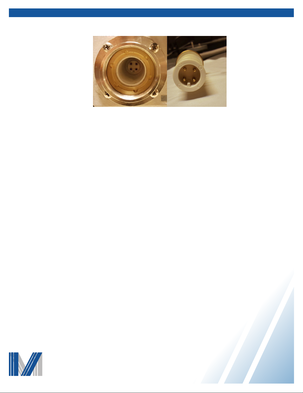
7. Line up the key notches and insert the connector into the receptacle. The connector may need to be rotated slightly to line up
with the key notches. Caution: Ensure safety interlocks are in place prior to connecting the tube to the generator.
8. Close the enclosure and all interlocks.
9. Turn on the lament to verify that the cable was properly connected. This can be done by turning the lament current to 0.5A
Caution: Do not exceed the beam current limits or the maximum power levels as outlined in the product datasheet for the
best tube life.
10. With the lament current conrmed, the high voltage can be applied in 10kV steps. Start at 20kV and step up to the full
operating voltage of 60kV. Once the tube is stable at 60kV, the tube voltage can be raised directly to 60kV and full operational
power; steps are not required after initial power up.
11. Power may now be applied to the tube by increasing the beam current. It is recommended that this be done in 0.2 mA steps the
rst time the tube is operated. The maximum power allowed is 150 watts and voltages up to 60kV, within the provided power and
volatge combinations. Caution: Do not exceed 150 watts of tube power at any voltage level.
12. The tube power levels are dependent on voltage. The tube should be operated according to the operational chart in gure 2.
Caution: Short term inputs of more than 150 watts are not allowed. This will cause permanent damage to the window.
13. It is permissible to attach thermocouples to the exterior of the tube to monitor the temperatures of the various surfaces. Kapton
tape works well to attach thermocouples without damaging the tube or cooling assembly. Do not attach thermocouples to the
beryllium window as this may damage the window. Please contact Moxtek for specic recommendations regrading the placement
of thermocouples.
NOTE: The lament monitor current of Spellman power supplies have been shown to have signicant variation. If you nd that
the desired beam current cannot be attained, please contact Moxtek for guidance on using increased current limits. The X-ray tube
may be permanently damaged in only a few seconds if the lament is run at excessive current levels.
Figure 12 - Left: Power supply receptacle Right: Tube
connector

MOXTEK
®
452 West 1260 North / Orem, UT 84057
Phone 801.225.0930 / Fax 801.221.1121
www.moxtek.com
For warranty and ordering information, please visit www.moxtek.com.
7
TUB-MAN-1020 Rev C
Subject to technical change without notice
Verify that the tube and the high voltage power supply are properly grounded before powering the tube on.
Operating Precautions-Warnings
Caution
Caution
Warning
Warning
Warning
MoxHPC tubes contain beryllium. Inhaling Beryllium dust may cause lung disease – refer to the MSDS.
Under normal use, Beryllium dust is not generated. If the Beryllium target is broken, a very small amount of
dust might be generated. If this occurs follow the instructions on the MSDS for cleanup.
MoxHPC X-ray tubes may become very hot during operation.
MoxHPC X-ray tubes produce x-ray radiation. HPC tubes are shielded with a metal shield and high-Z
potting materials. Extra shielding may be required depending on the application. ONLY OPERATE X-RAY
TUBES IN PROPERLY SHIELDED ENCLOSURES. It is the responsibility of the operator to ensure that
all applicable safety precautions are taken and observed.
MoxHPC X-ray tubes operate at high voltages Refer to the cable preparation instructions on page 4.
Precautions should be taken to protect the operator while applying high voltages to avoid serious injury or
death.
Table of contents
Other MOXTEK Medical Equipment manuals


Popular Medical Equipment manuals by other brands


GERATHERM
GERATHERM UniqueTemp instruction manual

lenstar
lenstar LS 900 Instructions for use

Karl Storz
Karl Storz UI400 Endoflator 40 instruction manual

Great Lakes
Great Lakes Kinesia 360 user guide

Body Clock
Body Clock Smart TENS Instructions for use

Hydrogen For Health
Hydrogen For Health PEM+ instruction manual