MOXTEK X-ray Sources User manual

MOXTEK
®TUB-MAN-1022 Rev A
Subject to technical change without notice
1
X-ray
Sources
Introduction
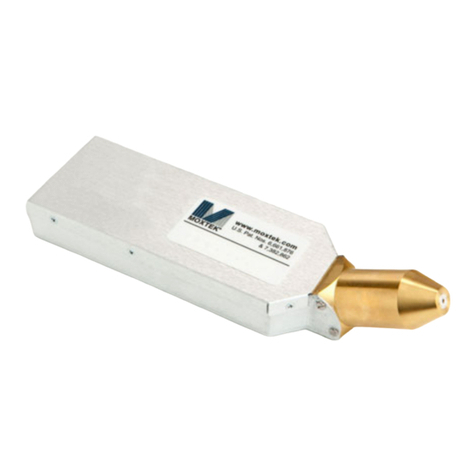
Moxtek manufactures low-power miniature X-ray sources for a variety
of applications including handheld XRF, Security, NDT and benchtop
instruments. Moxtek sources are small, lightweight and can be packaged
into customer enclosures. MOX140G is ideally congured for backscatter
and traditional imaging. MOX140G is capable of running up to 140kV
and 7W.
Figure 1: Fan Beam/Cone Beam
Table of Contents
• Introduction
• X-ray Source Characteristics
• Cooling
• Operating Conditions
• Mounting Information
• Initial Inspection
• Initial Setup
• Electrical Interface
• I2C Information
• Operating Precautions and Warnings
• Software and Setup
• Running the 140kV PC Controller Application
• Suggested Settings and Operation Parameters
1
2
2
2
2
3
3
3-4
3-4
5
6
7-9
10
MOX140G
Operation Manual

MOXTEK
®
Figure 2: Mounting Points Diagram
TUB-MAN-1022 Rev A
Subject to technical change without notice
X-ray Source Characteristics
2
Mechanical Specications
Tube Type Metal-Ceramic
Window 0.001in Tungsten
Operating Temp -10º to +50º C
Storage Temp -30º to +65º C
Cooling Forced air (as needed)
Weight 1.9kg/ 4.2lbs
Available Targets: Tungsten
X-ray Tube Characteristics
HV Polarity Bi Polar
High Voltage 140kV (max)
Beam Current 25uA - 50uA
Maximum Power 7W (50% Duty Cycle)
Focal Spot Size 1.00mm max FWHM
Maximum Exposure 30sec
Standard Warranty 1 year with typical usage
Cooling
Operating Conditions
Active or passive cooling will be needed depending on the application. Adhering to the limits specied in the X-ray
Source Characteristics will prevent any damage. Internal memory records operating temperature to facilitate failure
analysis. Operation outside of the permitted limits will void the warranty.
140kV tube anodes are grounded to the sheet metal and the power supply. Damage to the tube and or power supply
may result if a ground wire is not provided from the case ground to an appropriate equipment ground. Note that the
sheet metal is potted directly to the HVPS and should never be removed.
When operating the 140kV x-ray tube, adhere to the maximum settings as shown in Table 1 and 2. Failure to adhere
to these limits may cause damage to the x-ray tube and/or high voltage power supply. Failure to adhere to this
parameter will void the tube warranty. Internal memory records operation outside established limits for failure.
Mounting Information
Side screws are M2.5-0.45 THD and can be put in at a depth of 2mm. The front has 4 studs with dimensions M2 X
8mm. Mox140G, has four dual purpose screws at the front of the device. The studs are used for mounting purposes,
and for grounding. Removal of more than two studs will void the warranty. Once removed, studs cannot be added
back due to a risk in puncturing potting and harming electronic components.
Table 1: Mechanical Specications Table 2: X-ray Tube Characteristics

Initial Inspection
Pin # Name Description
1 VDC Main power, 12V +/- .5V
2 VDC Main power, 12V +/- .5V
3 VDC Main power, 12V +/- .5V
4 SCL I2C clock line
5 SDA I2C data line
6 ENABLE +5V to enable x-rays
7 GND Ground return
8 GND Ground return
9 GND Ground return
10 GND Ground return
11 +5V Aux power
12 +3.3 OR +5V I2C power*
Ensure proper ground connection to the shell.
Ensure all pinouts are correct.
Conrm everything is powered o when connecting to source.
If using the adapter board, proceeed to software section.
Initial Setup
Electrical Interface
The Samtec 10-pin FLE-105-01-G-DV connector is not used. This is for Moxtek use only. See Figure 3 below.
The Moxtek uses a Molex Picoblade connector # 53398-1271 (12-pins) is used to interface with MOX140G.
MOXTEK
®
3
Table 4: Pins Dened
Components Quantity Required
TUB0020X-W08 1
Molex 12 pin Picoblade connector # 53398-1271* 1
Cable – USB Type A-B 2.0* 1
12V power supply* 1
TUB-MAN-1022 Rev A
Subject to technical change without notice
Please Inspect Contents
*Optional items to purchase
Table 3: Components, Quantities
*Pin 12 should be powered with the same voltage used on the host’s I2C pull-up. If +3.3V I2C bus, is used +3.3V
should be used for pin 12. If +5V I2C bus is used, +5V should be used for pin 12.

MOXTEK
®
Pin 1
X
TUB-MAN-1022 Rev A
Subject to technical change without notice
4
To interface with the Molex Picoblade connector, use a Molex 0510211200 connector housing and a Molex
28AWG jumper lead socket to socket wires. (Molex 0006660013 is a good example). Power on the cable should
be o when connecting or disconnecting to the source.
Table 5: Addresses amd Lengths of Various Data
I2C Information
The master I2C bus requires 1K ohm to close to blue ribbon resistors for the pull-up voltage because of the nature of
the level shifter used.
Name Type Size (bits) Address (hex) Description
ctrl_Interlock unsigned 8 0x00 Status of pin 6 above, the enable signal
ctrl_Enable unsigned 8 0x01 Enable status
errorFlags unsigned 8 0x02 All errors are registered here
ctrl_vHWREV unsigned 8 0x03 hardware revision number
ctrl_vFWREV unsigned 8 0x04 rmware revision number
ctrl_cMFGYEAR unsigned 8 0x06 manufactured year
ctrl_cMFGMONTH unsigned 8 0x07 manufactured month
ctrl_cMFGDAY unsigned 8 0x08 manufactured day
ctrl_cTUBESN unsigned 24 0x09,0A,0B tube serial number
ctrl_cPSSN unsigned 24 0x0C,0D,0E power supply serial number
ctrl_vBrdTemp unsigned 16 0x0F,10 current board temperature
ctrl_vMaxTemp unsigned 16 0x11,12 maximum recorded board temperature
ctrl_vMinTemp unsigned 16 0x13,14 minimum recorded board temperature
ctrl_vHVSet unsigned 16 0x1B,1C high voltage set point
ctrl_vUASet unsigned 16 0x1D,1E beam current set point
ctrl_vnegHVMon unsigned 16 0x1F,20 negative high voltage monitor
ctrl_vUAMon unsigned 16 0x21,22 beam current monitor
ctrl_vposHVMon unsigned 16 0x23,24 positive high voltage monitor
Reading and Writing Voltage/Current and/Temperature Values
To read or write to the registers, the code must read or write a byte at a time and convert them to their full values
(if they are larger than 1 byte). So for example, on ctrl_vBrdTemp, user would read the two bytes starting at 0x0F.
Because data is stored little-endian format, byte 0x10 is the most signicant byte (MSB), so it is shifted up by 8
and added to byte 0x0F.
Figure 3: Ribbon cable connection
Electrical Interface cont.

MOXTEK
®
Bit
Number
Decimal
Value Error Description
1 1 Low HV Will throw an error if +/- KV is 5KV or lower than the set KV
2 2 High HV Will throw an error if +/- KV is 5KV or higher than the set KV
3 4 Low UA Will throw an error if uA is 5uA or lower than the set uA
4 8 High UA Will throw an error if uA is 5uA or higher than the set uA. If uA is set to 0,
will throw an error if uA is 10uA or higher
5 16 High Temperature Will throw an error if the internal temperature is 75°C or higher (Will be
adjusted based on environmental testing)
6 32 Low Temperature Will throw an error if the internal temperature is -7°C or lower (Will be
adjusted based on environmental testing)
Operating Precautions and Warnings
The X-ray source should be ramped up to 140KV to avoid arcing within the tube. If the source has been sitting idle
for a few hours or more, 3 seconds is recommended to ramp up to full voltage and power for the rst cycle. The
suggested procedure is to turn the source on at 70KV and 20uA. At 70KV, then take 10KV steps up to 140KV. Finally
turn the lament power up to full output. This should take about 3 seconds. If the source has been running, the ramp
rate time can be decreased to 0.5 seconds. The suggested procedure is to turn the source on at 70KV and 20uA, then
take 10KV steps up to 140KV. Finally turn the lament power up to full output. This should take about 0.5 seconds.
5
Variable Denition Related Equation
KVSET Desired KV ctrl_vHVSet = KVSET * 416.5
UASET Desired Current ctrl_vUASet = UASET * 518.4
KVMONP KV monitor positive KVMONP = ctrl_vnegHVMon / 169
KVMONN KV monitor negative KVMONN = ctrl_vposHVMon /169
UAbc Monitor beam current UAbc = ctrl_vUAMon * 0.0094
TKTemperature (Kelvin) TK = ctrl_vBrdTemp / 16
TC= TK-273.15
TCTemperature (Celsius)
Table 6: Variables Dened
Table 7: Bit Description
TUB-MAN-1022 Rev A
Subject to technical change without notice
I2C Information cont.

Figure 4: Moxtek Website Software Downloads Page
MOXTEK
®
6
Software and Setup
140kV Software Guide
1. Click on link to access the 140kV folder. See below page for location of software downloads.
2. Download the MOX140G Software folder
3. Unzip the downloaded le “MOX140G Software” onto desktop
4. Navigate to the “Drivers” folder
5. Open the “Moxtek 2.12.28-Signed” folder
6. Right click the “dp-chooser.exe” and select “Run as administrator”
7. Follow the prompts to install the driver
8. Once complete, run the “CDM21228_Setup.exe” le to install the FTDI driver
9. Follow the prompts to install the driver
10. Once complete, navigate to the main 140kV folder
11. Run the “140kV PC Controller.application” le
12. Once the 140kV PC Controller software is installed, run the program
13. A taskbar search for “140kV PC Controller” can locate the new le if needed
TUB-MAN-1022 Rev A
Subject to technical change without notice

MOXTEK
®
7
1. Start by ensuring the adapter board switch is in the o position
2. Connect the red cable to the adapter board, and then the 140KV source (as seen below)
3. Plug in the 12V power supply provided to both a wall outlet and the adapter board
4. Connect the provided USB cable to the adapter board, and to a PC that has the provided software installed.
5. Connect the interlock pins of the adapter board to a shielded safety interlock. It requires an
open or short condition. If the two pins are shorted together, the interlock is closed and the unit is safe to run. If the
two pins are open, or not connected to each other, the interlock is open and the unit will cease to emit any X-rays.
6. Power on the adapter board. Turn the switch from “OFF” to “ON”.
7. A green light should turn on, which conrms power is being provided, and a red light, meaning the safety interlock is
closed. The unit is ready to run.
TUB-MAN-1022 Rev A
Subject to technical change without notice
Running the 140kV PC Controller Application
Figure 5: USB cable to the adapter board
Figure 6: Interlock Pins
Figure 7: Safety Interlock Closed

8
Figure 8: Communication Port Section
Figure 9: Successful Connection
8. Go to the PC connected via USB to the adapter board, and start the “140KV PC Controller” application.
9. In the program, go to the Communication Port section and click the drop-down box. The program will recognize
the dapter board’s serial number. Click it. If nothing shows up, click out of the drop-down box and try again.
Communication can stall, and may take multiple attemps.
10. Once the connection is successful, it will populate certain elds with information about the connected source.
11. To run the source, click the “Enable Xrays” button, and put the desired values in the “Set Total KV” and “Set uA”
boxes. For the rst run of the day, please ensure that the “Std Ramp” rate is set to 50 KV/s or less. Once the unit is
warmed up, go ahead and set the “Std Ramp” to 140 KV/s for a 1 second ramp time to full power, or check the
“Fast Ramp” option, with 600 KV/s and 70 KV for the “Switch” value, and it will ramp to full power in 0.5
seconds.
MOXTEK
®TUB-MAN-1022 Rev A
Subject to technical change without notice
Running the 140KV PC Controller Application cont.

MOXTEK
®
**NOTE** There are additional software settings that are available.
The “Data Logging” section allows for creation of a text le that will populate with all the current settings and
readings at chosen “Log Interval” you choose. Log periors are set to default to every 0.5s, but can be changed to
any value between 0.5s to 3600s if desired.
The “Cycle Testing” section allows user to automatically turn the X-rays on and o at a specied duty cycle. The
max “On Time” recommended is 30s. The corresponding minimum recommended “O Time” is 30s. The “Add
20uA above 50KV” box should remain checked, and the “Filament Only” box should be blank.
If more details on these settings are needed, contact Moxtek.
TUB-MAN-1022 Rev A
Subject to technical change without notice
9
(Initial check and warm-up settings)
(Full output with 0.5s ramp rate)
Running the 140KV PC Controller Application cont.
Figure 10: Enable X-rays
Figure 11: Inital Check and Warm-up Settings

MOXTEK
®
Suggested Settings and Operation Parameters
• The source should be run between 10KV and 140KV.
• No beam current should be applied, unless the source is at 50KV or higher.
• 20uA should be the maximum current setting when below 100KV.
• If the source has been sitting overnight, or for about 24 hours, set the “Std Ramp” to 50 for the initial start-up.
After it has been running, the “Std Ramp” can be set to 140.
• At full output, the source should be set to 140KV and 50uA. 50uA should be the maximum current setting for the
source at any KV level.
• Active cooling is recommended to keep the temperature down on the source.
TUB-MAN-1022 Rev A
Subject to technical change without notice
10
Suggested Settings and Operating Parameters
Table of contents
Other MOXTEK Medical Equipment manuals
Popular Medical Equipment manuals by other brands

KaVo
KaVo KaVo Primus 1058 Life TM Care Instructions

ulrich medical
ulrich medical Obelisc CS 2931 Series Assembly and disassembly instructions with special cleaning instructions

DJO Global
DJO Global Vectra Genisys user manual
Guldmann
Guldmann 28445 manual

Gima
Gima OXY-5 Use and maintenance book

ResMed
ResMed Ultra Mirage Clinical Guide
