MOZELT CoolGen 4 User manual
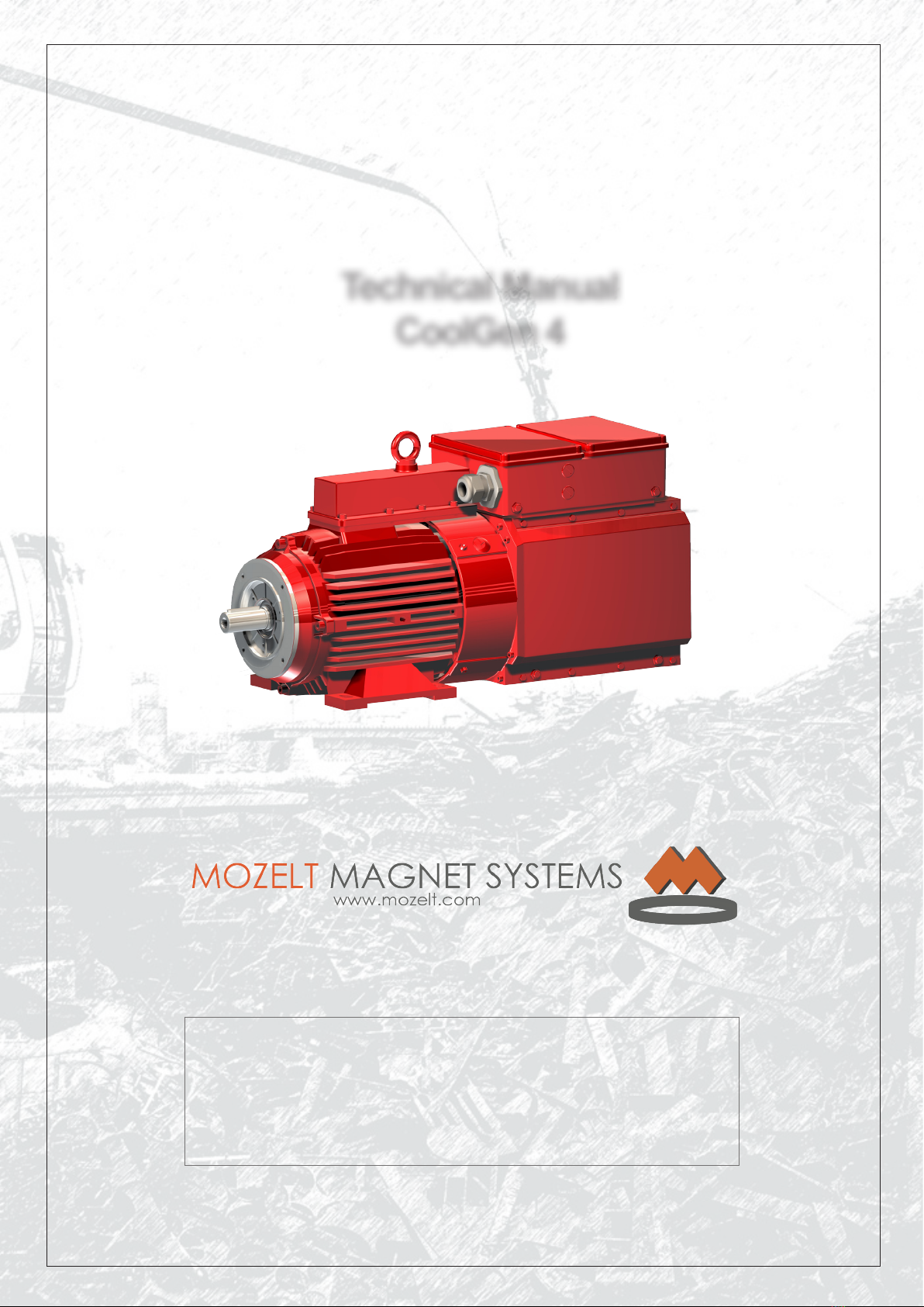
Technical Manual
CoolGen 4
Please observe the following safety
information and recommendations
before start-up !
MOZELT GmbH & Co. KG
Load liing magnet devices
Technical manual: CoolGen 4
Copyright: MOZELT GmbH & Co. KG, D-47269 Duisburg Edition: August 2014 Rev.: 00
Page 2
English
2. Usage to the Intended Purpose
Synchronous generators with integrated electronics are
components for installaon in machines which are used
in industrial plants.
Start-up of the power generators is not allowed before
it has been veried that the machine in which the
generators are installed conforms to the Machinery
Direcve.
The generators conform to the protecon goals of the
low-voltage direcve.
Operaon is only allowed when the EMC Direcve is
adhered to.
The technical data and informaon about connecon
condions are given in the nameplate and documentaon
and shall be adhered to by all means.
3. Transport, Storage
The instrucons for transport, storage and proper
handling are to be observed.
Defects detected aer delivery shall be reported
immediately to the carrier. Before start-up, the supplier is
to be noed, if necessary.
4. Installation
The installaon and cooling of the devices must be
carried out according to the provisions of the respecve
documentaon.
The generators are to be protected against inadmissible
loads. They are only to be touched in such a way that no
components are bent and/or insulaon clearances are
changed. Avoid touching the electronic elements and
contacts.
1. General
During use the generator may have live, bare, if
applicable, also hot surfaces. In the case of inadmissible
removal of the required cover, inappropriate use, wrong
installaon or operaon, there is the risk of death or
severe injury or material damage.
All work concerning the transport, installaon and start-
up as well as maintenance are to be carried out by
qualied technical personnel (IEC 364 and/or CENELEC
HD 384 or DIN VDE 0100 and IEC Report 664 or DIN VDE
0110 and naonal regulaon for accident prevenon or
VGB 4 are to be observed).
Qualied technical personnel according to these basic
safety references are persons who are familiar with the
installaon, assembly, start-up and operaon of the
product and possess corresponding qualicaons for
their acvity (dened in IEC 364 or DIN
VDE 0105).
For reasons of safety and the preservaon of
documented system data and funcons, repairs to the
generator or its components may only be undertaken by
the manufacturer.
Technical data, as well as data concerning connecon
condions, are to be taken from the rang plate and the
documentaon and are to be strictly observed.
Safety information / General information
All passages provided with the „warning“ sign in the manual contain informaon
important for avoiding danger!
WARNING
All passages provided with the „cauon“ sign in the manual contain informaon
necessary for avoiding damage to the power supply or accessories!
CAUTION
It is absolutely necessary to observe the
following warnings.
If these warnings are not observed,
serious personal injuries with fatal result,
severe injuries to health or considerable
damage to property cannot be ruled out!
WARNING
MOZELT GmbH & Co. KG
Load liing magnet devices
Technical manual: CoolGen 4
Copyright: MOZELT GmbH & Co. KG, D-47269 Duisburg Edition: August 2014 Rev.: 00
Page 3
English
5. Electrical Connection
When working on energized power generators, the
applicable naonal accident prevenon regulaons shall
be observed.
The electrical installaon is to be carried out in
accordance with the relevant regulaons (e.g. line cross
secons, provision of safety arrangements). Further
instrucons are given in the documentaon.
The manufacturer of the system is responsible for
adherence to the EMC legislature. Instrucons for
installaon in accordance with the EMC Direcve are
given in the documentaon of the power generators.
6. Operation
Installaons into which the generators are built must be
equipped, if necessary, with addional monitoring and
protecon devices.
The manufacturer’s documentaon is to be observed.
Aer separang the generators from the drive unit, live
components and line connecons must not be touched
when the generator spindle is running, due to the
voltage.
All covers are to be kept closed during operaon.
In the electronics, there are intermediate
circuit capacitors.
Their discharge may take longer than 10
minutes!
Before start of work, verify isolaon from
power supply!
If this is not observed, serious personal
injuries with fatal result, severe injuries
to health or considerable damage to
property cannot be ruled out!
WARNING
7. Applicable Documents
A prerequisite for the use of a power
generator is that these operang
instrucons have been read and
understood. In parcular, the safety
notes contained there are to be
observed.
If these notes are not observed,
serious personal injuries with fatal
result, severe injuries to health or
considerable damage to property
cannot be ruled out!
WARNING
MOZELT GmbH & Co. KG
Load liing magnet devices
Technical manual: CoolGen 4
Copyright: MOZELT GmbH & Co. KG, D-47269 Duisburg Edition: August 2014 Rev.: 00
Page 4
English
Table of contents
1. Technical descripon 5
1.1 General informaon 5
1.2 Range of Applicaon 5
1.3 Descripon 5
1.4 Funcon mode 5
1.5 Protecon Concept, Behaviour in the Case of Faults 6
1.6 Safety regulaons magnet operaon 6
2. Technical Data 7
2.1 Performance Data 7
2.2 Accessories 7
2.2.1 MFD display 7
2.3 Generator Drives 8
2.3.1 Belt Drives 8
2.3.2 Hydraulic Drives 8
3. Assembling 9
3.1 Assembling instrucons 9
3.2 Installaon of „BELL CLUTCH“ Coupling 9
3.3 EMC Notes Electromagnec Compability 10
3.3.1 Interference Immunity 10
3.3.2 Interference Radiaon 10
3.4 Magnet Connecon 10
3.5 LED Funcons 10
3.6 Control cable 11
3.7 Terminal Box 11
3.8 Terminal Block 12
3.8.1 Start command via switch line on the MFD display 12
3.8.2 Start Command via Terminal Block 12
3.9 USB Connecon 12
3.10 Cable Allocaon 230 Volt 13
3.11 Dimensional Drawings Power Generator 14
4. Commissioning 15
4.1 Safety Notes 15
4.2 Operang instrucons 16
4.3 Operaonal indicators MFD 17
4.4 Fault indicators MFD 19
4.5 Assembly Plan Power Generator 22
4.6 Mechanical Speed Measurement 23
5. Shutdown 23

MOZELT GmbH & Co. KG
Load liing magnet devices
Technical manual: CoolGen 4
Copyright: MOZELT GmbH & Co. KG, D-47269 Duisburg Edition: August 2014 Rev.: 00
Page 5
English
English
1.2 Range of Applicaon
The MOZELT power supply system with synchronous
generator is designed to supply and acvate load liing
magnets on mobile excavators.
At present it is available with the output sizes 13, 20 and
30 kW.
Due to the duty rang of 100% (ED), the generators are
the opmal soluon for loading and handling in the
industrial scrap metal industry.
The maintenance-free and compactly designed generator
system is powered by the diesel engine of the excavator
or the hydraulic system.
1.3 Descripon
* rpm = revoluons per minute
1. Technical descripon
1.1 General informaon
MOZELT does not take any liability for the consequences
resulng from inappropriate, negligent or incorrect
installaon or operaon of the synchronous generator
with integrated electronics.
The condions of guarantee of MOZELT in the valid
version at the me of purchase shall apply for the
equipment.
The content of the present manual is considered correct
at the me of prinng for the indicated generator
version. MOZELT reserves the right to make changes
which represent a technical advantage.
Any change to the generators which is not performed by
us, including the installaon of addional devices, can
lead to a change of the technical specicaon and the
content of the documentaon and manual and therefore
leads to an exclusion of our liability, also from the
guarantee.
CAUTION
CAUTION
CAUTION
CAUTION
The rated speed of a generator of the
CG 4-series is around 3000 rpm*.
In this connecon, the range from
2700 rpm to 3400 rpm is to be
regarded as the tolerance range.
It is parcularly important that the
rotaonal speed remains constant
and no uctuaons occur!
The most important operang and switching states
are indicated in a mul-funcon display (MFD) in the
operator‘s cab.
1.4 Funcon mode
The transformaon of brushless three-phase voltage into
DC voltage in the generator and its contactless delivery
aer acvang the generator provides the operator with
comfort and the highest safety.
The generator CG 4 is praccally maintenance-free. The
abolion of contactors or relay circuits in the external
electrical plant area, as well as the absence of adjustment
buons or potenometers, protects this installaon
system against faulty operaon.
Important!
The electronic modules are equipped
with electrostacally sensive CMOS
and MOS components.
It is absolutely necessary to observe the following
instrucons since otherwise these switching circuits
can be destroyed.
• For servicing work, rst equipotenal bonding (stac
charging) is to be ensured between electronic modules,
tools, measuring devices and personnel.
• Grasp electronic modules by the edges only, do not
touch components and their connecons.
MOZELT GmbH & Co. KG
Load liing magnet devices
Technical manual: CoolGen 4
Copyright: MOZELT GmbH & Co. KG, D-47269 Duisburg Edition: August 2014 Rev.: 00
Page 6
English
The generator CG 4 is independent of the on-board
electrical system, and produces its own supply voltage for
internal control and monitoring. The machine is overload
and short-circuit proof.
The correct supply voltage is regulated automacally for
the magnet aached to the generator and the necessary
release me is opmized and implemented for every
kind of material to be loaded.
The operator can read o important operang condions
from the funcon display (MFD) in the operator‘s cab.
The display of the relave duty rang in % (ED) is to be
observed for the range 50% to 100% of the aached
load liing magnet. If this exceeds the value 80% ED, the
danger of the magnet overheang is signalized by a red
LED.
It is then recommended to change the work mode or to
take a break to allow the magnet to cool down.
The localizaon of work related errors in the 230 V cable
system is directly possible. Cable damage and
shortcircuits in the 230 V cable system lead to immediate
disconnecon of the supply voltage (passive protecon
for individuals).
1.5 Protecon Concept, Behaviour in the Case of
Faults
The intrinsic safety of the power generator is enhanced
by an extension of the monitoring funcons, Installed
monitors ensure a high operaonal reliability of the
system.
In case of fault, the electronics is immediately blocked. At
the same me, a fault is indicated and the LED „Ready for
operaon“ exnguishes.
The following monitoring funcons are integrated:
• Overload protecon
• Insulaon monitoring
• Overtemperature protecon
• Overspeed protecon
• Open magnec circuit
• Short circuit
1.6 Safety regulaons magnet operaon
The operaon of a load liing magnet on a mobile
excavator represents a special mode of operaon and
an increased safety risk. In contrast to working with
a hydraulic grabber, the magnet picks up all available
ferromagnec material immediately aer it is switched
on.
This may even be more than the load-carrying capacity of
the mobile excavator allows.
Similarly, the magnet suddenly releases the lied
material aer it is switched o, if there is cable damage
or a short-circuit in the magnet feed cable. This can
lead to dangerous situaons in the working vicinity, for
example, if falling material causes other objects to be
hurled up by lever force. Furthermore, it is not excluded
that pieces of scrap iron may separate from the magnet
during a swiveling procedure, if these are located at the
lower end of the lied material cluster.
For these reasons, it is parcularly important to observe
the following principle:
WARNING
WARNING
The magnet can oscillate strongly aer load release!
For this reason, the mechanically safe aachment of
the magnet in the form of a special magnet suspension
at the end of the arm on the mobile excavator is highly
recommended!
Do not swivel the working equipment
or change the locaon of the
excavator with the magnets
switched on without a
payload - unintenonally
lied materials can lead to
human injury by lever force!
While working with the load
liing magnet it is forbidden to
stand within the extended reach of
the excavator
MOZELT GmbH & Co. KG
Load liing magnet devices
Technical manual: CoolGen 4
Copyright: MOZELT GmbH & Co. KG, D-47269 Duisburg Edition: August 2014 Rev.: 00
Page 7
English
English
2. Technical Data
2.1 Performance Data
Model CoolGen 4 13 kW 20 kW 30 kW
Rated voltage 230 V 230 V 230 V
Max. output current 57 A DC 87 A DC 130 A DC
Operang speed range * 2700....3400 U/min **
Venlaon Internal venlator
Weight 58 kg 87 kg 135 kg
Protecon class IP 55
Permied ambient
temperature
-25° C…..+50° C non-condensing
Installaon height < 1000 m NN, above 1000 m output reducon of 1% per 100 m
2.2 Accessories
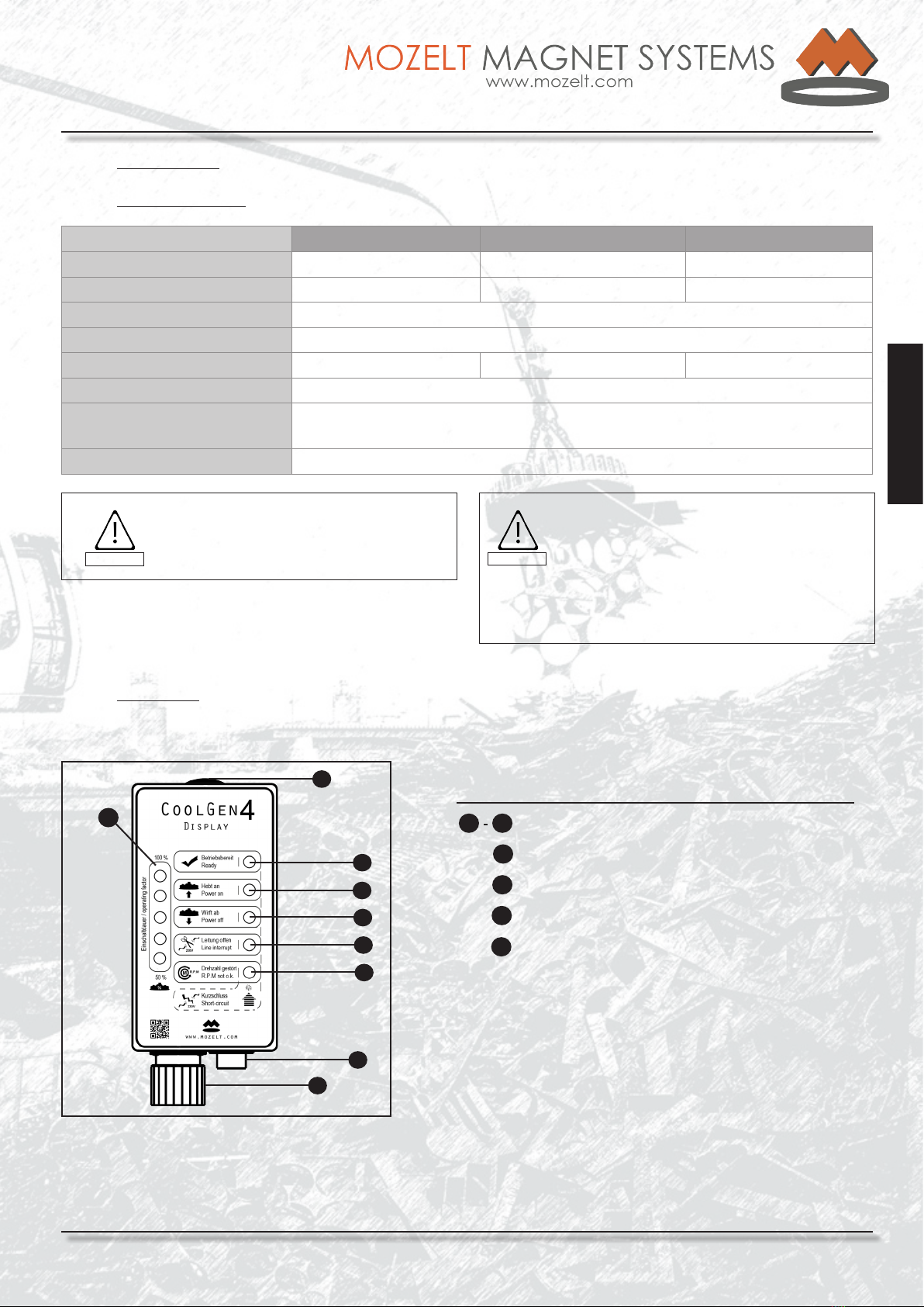
2.2.1 MFD display
The data indicated on the nameplate
are of signicance!
CAUTION
When the power generator is installed
in a casing or under a cover the
temperature of the air used for cooling
should not be more than 50 °C max.
(maximum internal temperature of the
casing / cover!)
CAUTION
1
2
3
4
5
Fig.: 1 | General view CG4 Display
The dierent operang condions of the generator are
indicated in the funcon display (MFD) via LEDs.
An addional 6 LEDs indicate the working loading
ulizaon of the magnet (On/O rao) within the range
50…100%.
The release switch to turn the magnet on/o is also
aached to this display unit.
6
7
9
8
The most important operang states can be immediately
read o:
15Funcon and fault indicaon
6Relave duty factor of the magnec disks in %
Cover USB connecon (servicing purposes)7
Screw terminal for switch line / pushbuon
8
Connecon for control line
9
* guaranteed performance data at 100 % duty factor
** in the range of 2350 rpm to 2700 rpm, limited operaon at
reduced output voltage is possible.

MOZELT GmbH & Co. KG
Load liing magnet devices
Technical manual: CoolGen 4
Copyright: MOZELT GmbH & Co. KG, D-47269 Duisburg Edition: August 2014 Rev.: 00
Page 8
English
2.3 Generator Drives
Depending on the type of mobile excavator, the power generator is mechanically or hydraulically driven.
Both variants are designed so that the necessary operang speed of the power generator is ensured as soon as the
diesel engine has reached its full speed.
2.3.1 Belt Drives
To ensure that the belt runs straight both axes must be ush with each other. The sha axes shall be parallel with the
axis of the generator.
It is recommended to use a Laser alignment device for aligning the belt pulleys.
For adjustment of the pretension, we recommend the use of belt measuring devices. During and aer installaon, the
belt is to be revolved several mes. This causes uniform seling of the pulley.
The rst check of the run-in belt pulley is carried out aer 0.5 to 4 hours.
The belt tension should be checked every 6 to 12 months and, if necessary, corrected.
2.3.2 Hydraulic Drives
Hydraulic generator drives are always to be supplied with a priority ow of hydraulic oil.
This means the supply ow should not be adversely aected by motor uctuaons, liing, travelling or other
movements. Depending on the manufacturer of the construcon machine, this is implemented in various technical
designs. Please ask the respecve manufacturer for informaon on this maer or contact us for the alternave
soluon of the „HydraBrain“ system.
With some hydraulic drives, opmum operaon is also possible at low speed of the diesel engine. For this, please
check the manual of the mobile excavator manufacturer.
Never reach into the running belt
drive!
WARNING
Never operate the power generator
without belt guard!
WARNING
Fig.: 2 | Belt drive
Fig.: 3 | Hydraulic drive with „BELL CLUTCH“ coupling
For hydraulic motor drives, speed peaks up to 4000 rpm are allowed at the moment of shutdown
of the magnet, if they do not last longer than 0.5 seconds. At speeds above 3400 rpm and below
2700 rpm, magnet operaon is not, or only to a limited extent, possible.
CAUTION
CAUTION
It is parcularly important that the speed
remains constant and does not show any
uctuaons!
CAUTION
Speeds above 3400 rpm can destroy the
power generator!
CAUTION
The speed should be measured not only
during no-load operaon, but also during
the starng and shutdown phase!
MOZELT GmbH & Co. KG
Load liing magnet devices
Technical manual: CoolGen 4
Copyright: MOZELT GmbH & Co. KG, D-47269 Duisburg Edition: August 2014 Rev.: 00
Page 9
English
English
3. Assembling
3.1 Assembling instrucons
3.2 Installaon of „BELL CLUTCH“ Coupling
Table of distances coupling halves
1
2356
78
5
8
4
Generator type Hydraulic motor Distance A Distance B
T4002 / CG4 13 kW Bosch-Rexroth 16 ccm / Sunfab 17 ccm 0 mm 0 mm
T4002 / CG4 13 kW Bosch-Rexroth 23 ccm / Sunfab 25 ccm 12 mm 12 mm
T4002 / CG4 20 kW Bosch-Rexroth 23 ccm / Sunfab 25 ccm 11 mm 0 mm
1
2
3
4
Hydraulic motor
Adaptor ring for 16/17 ccm hydraulic motors
Clutch bell
Cover for speed measurement
6
7
8
9
Clamping bushing on the hydraulic motor
Coupling spider
Clamping bushing on the power generator
Sha / end shield on the power generator
5Coupling half
Fig.: 4 | Explosion drawing „BELL CLUTCH“ coupling
Fig.: 5 | Distance drawing coupling halves
1
CAUTION
The environmental atmosphere must be free of aggressive dust, corrosive vapours, gases and
liquids. The generator is to be protected against moisture according to IP 55.
Synchronous generators with integrated electronics may not be operated in areas classied as
dangerous, unless they are installed and cered in an approved housing.
The generators are designed for foot assembly
Make sure that the heat produced by the generator can be dissipated. The venlator screen must always be kept
free, in order to ensure an adequate supply of fresh air. All heat sources must be considered when determining
the ambient temperature, so that the temperature does not rise above the permissible maximum value for the
generator.
MOZELT GmbH & Co. KG
Load liing magnet devices
Technical manual: CoolGen 4
Copyright: MOZELT GmbH & Co. KG, D-47269 Duisburg Edition: August 2014 Rev.: 00
Page 10
English
3.3 EMC Notes Electromagnec Compability
As all electrical equipment, synchronous generators with integral electronics can emit electromagnec energy and
be inuenced by it.
Electromagnec compability requires on the one hand that equipment is insuscepble to interference as regards
electromagnec radiaon, i.e. that they cannot be inuenced, and on the other hand does not exceed a certain
level of interference radiaon, and as a consequence does not interfere with other equipment.
These levels depend on the environment in which the equipment is operated. Here a disncon is made between
industrial and residenal environments including business and commercial as well as light-industrial environments.
This chapter is to serve as a guideline for installaon of the drives to avoid EMC problems and realize an EMC-
compliant wiring in accordance with the EMC Direcve.
3.3.1 Interference Immunity
CG4 ... are extremely suscepble to interference as regards electromagnec radiaon.
Interference immunity is achieved for the equipment without addional aids. In addion, all inducon components,
such as relay and contactor coils, electromagnec brakes, etc. are to be interference-suppressed using suitable
components (e.g. RC elements).
3.3.2 Interference Radiation
To avoid unallowable interference radiaon it is absolutely necessary to observe the given wiring instrucons.
Non-line-related interference radiaon is directly emied by the integrated electronics and wiring within a
frequency range of 30 MHz to 1 GHz. It is mainly generated by the fast logic circuits and has very low energy.
Problems with other electronic equipment due to this are not be expected.
Line-related interference radiaon in the frequency range of 150 kHz to 30 MHz is mainly caused by switching of
the power semiconductors. Because of the independent network, no problems with other equipment will occur.
3.4 Magnet Connecon
The electrical line connecons and plug-in connecon (plug / coupling) are matched to the corresponding output of
the power generators. In the process, the highest requirements are made on funconality and safety.
Please only use original MOZELT spare parts as required.
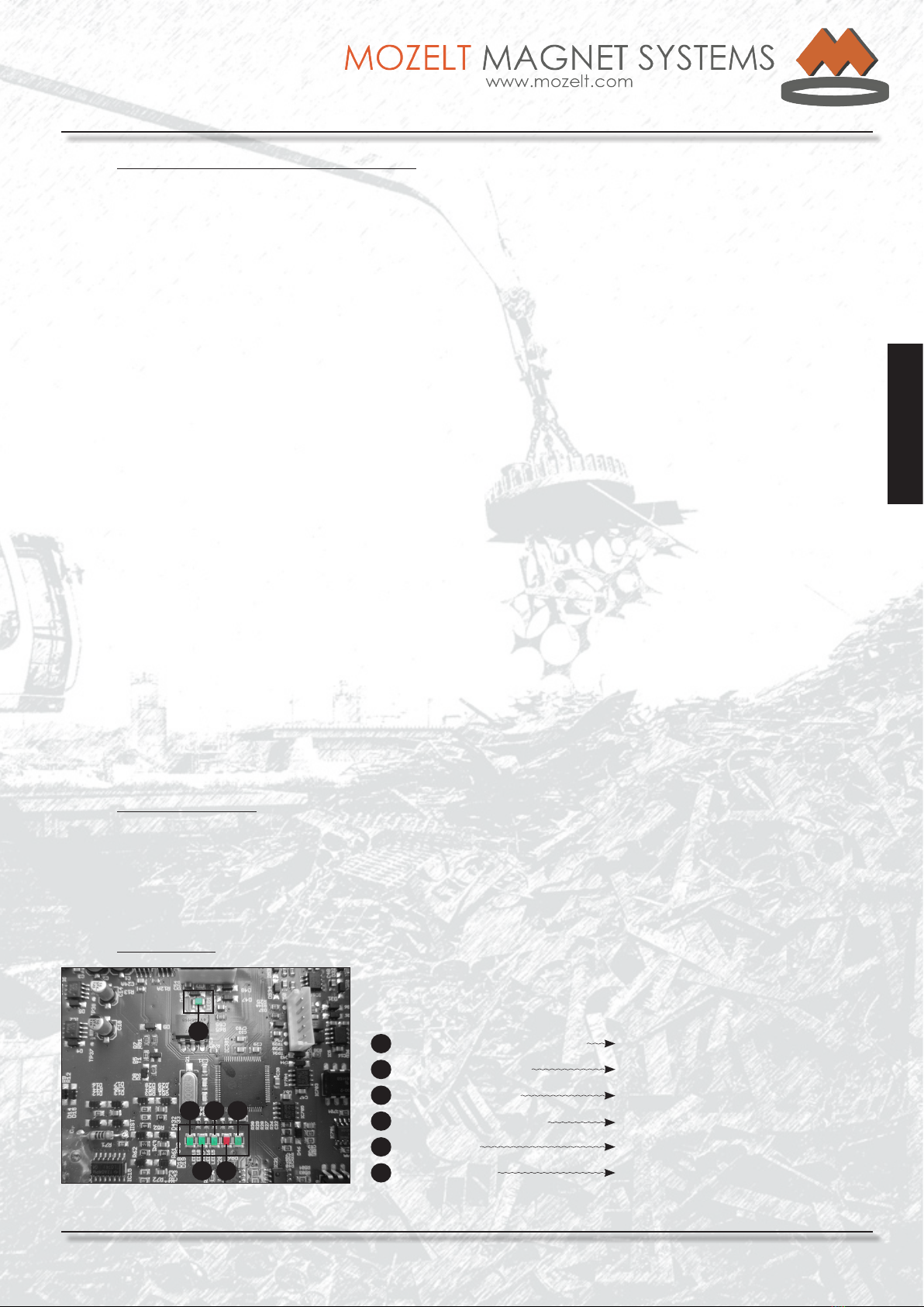
3.5 LED Funcons
Fig.: 6 | LED funcons on the control card
Various operang states are in addion indicated on the control card
of the power generator via LED. The following operang states can be
read o via the LED:
1Ext. pushbuon input LED Status external pushbuon input via terminal block
2
3
4
5
Signal output LED Selecon signal output
Status LED Status „On“
Supply voltage LED Internal electronics supply voltage available
Fault LED LED signals a fault
6Stand-by LED Stand-by LED
2 4 6
35
1

MOZELT GmbH & Co. KG
Load liing magnet devices
Technical manual: CoolGen 4
Copyright: MOZELT GmbH & Co. KG, D-47269 Duisburg Edition: August 2014 Rev.: 00
Page 11
English
English
3.6 Control cable
Cable for control signals must be shielded. The cable shield must be connected to the connector shell.
The signal ground must not be grounded.
If necessary, please use only original spare parts.
3.7 Terminal Box
Before isolaon of power generator and electronics, the following warning should be observed:
The discharge me begins aer nal shutdown of the power generator!
Fig.: 8 | Connecon control line on the power generator
5
1Magnet connecon 230 V DC
2
3
4
5
Protecve earth conductor connecon
Terminal block
USB connecon
Screw terminal control line
Fig.: 7 | Terminal box
Steuerelektronik
1
4
2
3
5
6
6Control card
WARNING
In the electronics, there are intermediate circuit capacitors.
Their discharge may take longer than 10 minutes!
Before start of work, verify isolaon from power supply!
If this is not observed, serious personal injuries with fatal result, severe
injuries to health or considerable damage to property cannot be ruled out!
Fig.: 9 | Terminal block
3
MOZELT GmbH & Co. KG
Load liing magnet devices
Technical manual: CoolGen 4
Copyright: MOZELT GmbH & Co. KG, D-47269 Duisburg Edition: August 2014 Rev.: 00
Page 12
English
3.8 Terminal Block
Wiring of the hydraulic and temperature sensor terminals is always arranged in the same way. Due to the various
switch wirings there are the following possibilies:
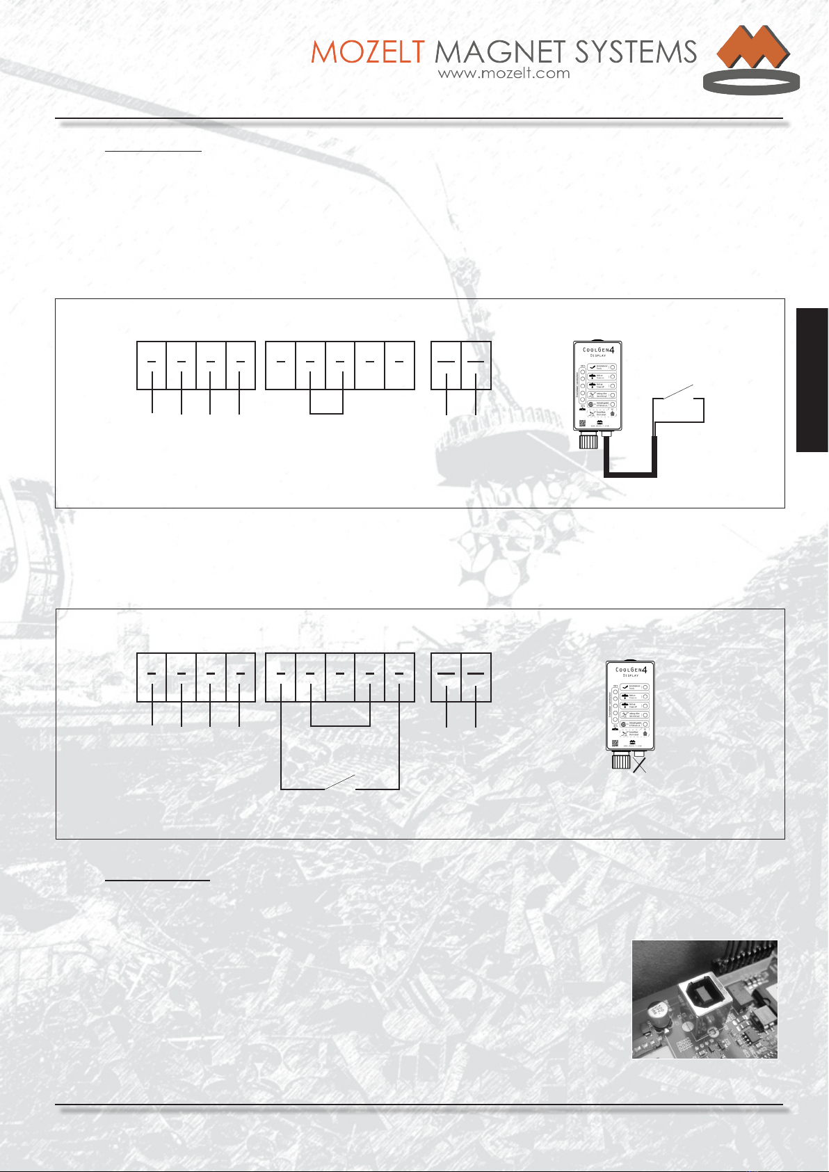
3.8.1 Start command via switch line on the MFD display
During run-up of the power generator, the electronics detects a signal at terminal 7.
Thus, the display pushbuon on the MFD is acvated and the pushbuon input at terminals 5 & 9 is deacvated.
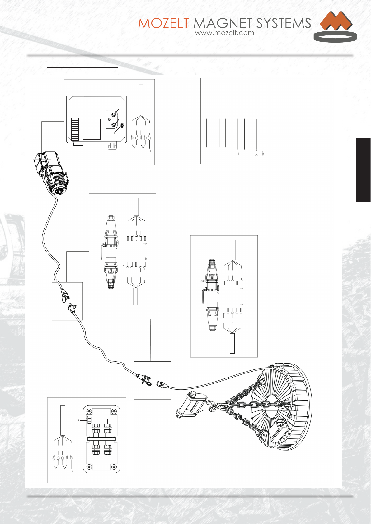
3.8.2 Start Command via Terminal Block
During run-up of the power generator, the electronics detects the missing signal at terminal 7.
Thus, the display pushbuon is deacvated and the pushbuon input on terminals 5 & 9 acvated.
12 3 4 5678910 11
Hydraulic control
HydraBrain
Pushbuon wiring Temperature sensor
generator
Bridge Internal
Temperature
sensor
MFD Display
Keying signal
Keying signal
on the display
deacvated
3.9 USB Connecon
On the control card and MFD, there is an USB port. Both USB connecons are idencal and allow the following
funcons via the DriveSo service soware (see Annex DriveSo):
• Changing of the output voltage
• Changing of the ramps of the liing and detachment behaviour of the magnet
• Adjustments for sorng operaon
• Fault analysis
• Operang states (speed, temperature, operang hours, output voltage, etc.)
• Oscilloscope funcon
• Firmware updates
12 3 4 5678910 11
Hydraulic control
HydraBrain
Pushbuon wiring Temperature sensor
generator
See Annex
„HydraBrain“ Unit
Bridge Internal
Temperature
sensor
MFD Display
Switch line
Keying signal
Fig.: 10 | Terminal allocaon on the terminal block (pushbuon on MFD acvated)
Fig.: 11 | Terminal allocaon on terminal block (pushbuon on terminal block acvated)
Fig.: 12 | USB connecon on
the control card
See Annex
„HydraBrain“ Unit
MOZELT GmbH & Co. KG
Load liing magnet devices
Technical manual: CoolGen 4
Copyright: MOZELT GmbH & Co. KG, D-47269 Duisburg Edition: August 2014 Rev.: 00
Page 13
English
English
BK
GY
BN
BU
GNYE
1
2
3
4
GNYE
BK
BN
GY
BU
GNYE
BK
GY
BN
BU
GNYE
1
2
3
N
1
2
3
N
BK
BN
GY
BU
GNYE
BK
BN
GY
BU
GNYE
1
2
3
N
1
2
3
N
P1
P2
P1
P2
BK
BN
GY
BU
GNYE
P1
P2
Black
Brown
Grey
Blue
Green - Yellow
Protecve earth cond.
Pole 1
Pole 2
Adherent sleeves
Ring cable lugs
Legend
Plug-in connecon on the strut
Magnet connecon line | beam line
Oponal addional plug-in connecon on the beam Terminal box on the generator
Terminal box at the magnet
P1 P2
P1
P2
Fig.: 13 | Cable allocaon magnet system wiring system 230 V
3.10 Cable Allocaon 230 Volt

MOZELT GmbH & Co. KG
Load liing magnet devices
Technical manual: CoolGen 4
Copyright: MOZELT GmbH & Co. KG, D-47269 Duisburg Edition: August 2014 Rev.: 00
Page 14
English
3.11 Dimensional Drawings Power Generator
Fig.: 14 | Power generator CG4 30 kW
Zahnwelle: W 30x2x30x14x9g DIN 5480
Spline Shaft: W 30x2x30x14x9g DIN 5480
Fig.: 15 | Power generator CG4 20 kW
Fig.: 16 | Power generator CG4 13 kW
MOZELT GmbH & Co. KG
Load liing magnet devices
Technical manual: CoolGen 4
Copyright: MOZELT GmbH & Co. KG, D-47269 Duisburg Edition: August 2014 Rev.: 00
Page 15
English
English
4. Commissioning
The generator‘s internal electronic unit has been completely balanced at the works and does not require any
further adjustments and checks. Only the „MFD“ display is to be connected with the generator system via a 9-pole
cable, double-ended plug connecon.
To this display unit the release pushbuon is connected via the 3-pole plug. The magnet is connected via two
clamping bolts. Operaon is possible in both direcons of rotaon without rewiring.
4.1 Safety Notes
It is required that the user has familiarized himself with the operang instrucons before commissioning of the
power generator.
It is absolutely necessary to observe the following warning notes:
WARNING
During operaon of this power generator, dangerous voltage may occur which can cause death
or severe bodily injuries! Utmost care is advised during work on the power generator.
WARNING
• Only qualied maintenance and repair personnel are permied to examine and repair
the unit or parts of it.
• Never leave open or open terminal connecon spaces, covers and 230-volt plug-and-
socket devices on the power generator and magnet with the drive motor in operaon!
• Stand on an isolang mat (suitable for electrostacally sensive devices) and make
sure that this mat is not earthed before performing commissioning work on
the switch-on unit.
WARNING
Before start of work, verify isolaon from power supply. Make sure that no voltage is applied to
the magnet connecon. If this note is not observed, severe or even fatal bodily injuries may be
caused!
WARNING
• When working on the connected machine or supply leads to the machine, the power
generator should be shut down and locked out in O posion.
• According to VDE 1060, safety isolaon by locking the release pushbuon is not allowed.
• A safety isolaon blocks the power modules in the case of faults. However, with this
funcon it cannot be ensured that there is no residual voltage at the output terminals
and inside the power generator. Aer opening of the power generator, the
remaining residual voltage should be measured at the usually live parts. Before touching
electrical contacts make sure that no voltage is applied to voltage-carrying parts.
• Do not use any measuring equipment of which you know that it is in damaged or
defecve condion.
WARNING
Important!
In case of fault, modules potenal-free during operaon may carry voltage. Before start of work
on the equipment, make sure by measurement aer safety isolaon that the equipment is
deenergized. If this note is not observed severe or even fatal injuries may be caused.

MOZELT GmbH & Co. KG
Load liing magnet devices
Technical manual: CoolGen 4
Copyright: MOZELT GmbH & Co. KG, D-47269 Duisburg Edition: August 2014 Rev.: 00
Page 16
English
The V-belt tension with belt drives is to be examined and,
if necessary, the belts are to be reghtened according to
regulaon.
Unless otherwise expressly stated, the diesel engine
of the mobile excavator is to be brought up to full
revoluons. The generator then runs within its operang
range. The yellow LED „Ready“ automacally appears on
the mul-funcon display MFD in the operator‘s cab.
Switching the power supply and/or the load liing
magnet on and o is usually accomplished with a switch
located in the handle. Depending on the type of device,
this must be energized with a separate switch in the
control console of the mobile excavator. For this purpose
also see the notes in the manual for the mobile excavator.
If the switching-on command is given, then the generator
CG 4 connects the voltage contactless through to the load
liing magnet. If the command is given to switch o, then
the generator automacally leads to its demagnezaon.
During the process of demagnezing, whereby the
magnet releases its load (approx. 1 sec), no renewed
switching-on command can be given.
Switching-on of the installaon is only possible, if a load
liing magnet is aached to the system.
Switching on the magnet:
Operate the buon in the control lever 1 x.
In addion to the yellow LED „Ready“, the green LED
„Power on“ lights up in the mul-funcon display.
Switching o the magnet:
Operate the same buon in the control lever again only
1 x. The already illuminated green LED „Power on“ now
goes out and a red LED with „Power o“ lights up.
Aer the load has been dropped, this goes out
automacally. The permanently illuminated LED „Ready“
during the shiing processes indicates that a renewed
procedure is now possible and that the power can be
switched on. Breakdowns are indicated by illuminated
red LEDs.
The meaning and eliminaon of such disturbances are
explained using gurave illustraons and texts under -
Breakdown indicators on the MFD -.
Make sure that ...
• the person supervising the trial run is qualied
and competent to carry out, and supervise,
the mechanical and electrical installaon.
• the nominal values of the power generator
correspond to the operang condions.
• the power generator is securely xed.
• the power generator is adequately venlated.
Safety measures shall be properly adhered to!
4.2 Operang instrucons
When working with the load liing magnet, the pernent
industrial safety and accident prevenon regulaons are
to be observed.
In addion, liing magnet operaon may only be started,
if the operator knows the „Safety Regulaons Magnet
Operaon“ (see Table of Contents).
Before start-up of the power supply CG 4, the operator
should ensure that the 230V cable system is in an
opcally perfect condion. Plugs and plug connectors are
to be examined for ghtness of t, the anchoring device
of the magnet connecng cable is to be examined for
perfect funcon.
WARNING
Before start-up, subject the complete
system to a visual inspecon!
WARNING
Before start-up, check correct seang
of the V-belts!
WARNING
Connect only liing magnets to the
system! For other electrical consumers,
operaon is not allowed!
WARNING
Before start of all work on the enre
system, shut down the drive motor!

MOZELT GmbH & Co. KG
Load liing magnet devices
Technical manual: CoolGen 4
Copyright: MOZELT GmbH & Co. KG, D-47269 Duisburg Edition: August 2014 Rev.: 00
Page 17
English
English
4.3 Operaonal indicators MFD
Indicaon: - LED 1 (yellow), „Ready“
Note: Generator is waing for switching-on command.
1
Generator running in the working range
Fig.: 17 | MFD signals Ready for operaon
Indicaon: - LED 1 (yellow), „Ready“
- LED 2 (green), „Power on“
Note: Magnet liing material.
1
Aer switching-on command given via operang switch, the magnet lis
Fig.: 18 | MFD signals an acvated magnet
2
Indicaon: - LED 1 (yellow), „Ready“
- LED 3 (red), „Power o“
Note: Magnet releases the material.
1
Aer switching-o command given via operang switch, magnet releases
load
Fig.: 19 | MFD signals throwing-o of
the material
3
MOZELT GmbH & Co. KG
Load liing magnet devices
Technical manual: CoolGen 4
Copyright: MOZELT GmbH & Co. KG, D-47269 Duisburg Edition: August 2014 Rev.: 00
Page 18
English
Indicaon: - LED 1 (yellow) „Ready“,
- LED 2 (green, ashing) „Power on“.
Note: - Magnet lis material. The power generator operates in the
sorng mode .
1
Aer the start command has been given via the operang pushbuon, the
magnet lis
Fig.: 20 | MFD signals an acvated
magnet in the sorng mode
2

MOZELT GmbH & Co. KG
Load liing magnet devices
Technical manual: CoolGen 4
Copyright: MOZELT GmbH & Co. KG, D-47269 Duisburg Edition: August 2014 Rev.: 00
Page 19
English
English
4.4 Fault indicators MFD
Faults are oen indicated by red LED.
Indicaon: LED 1 (yellow), „Ready“.
Possible cause : - Interrupon in switch cable
- Operang switch defecve
- Control cable defecve
Aer switching-on command given via operang switch, no funcon
1
Fig.: 21 | Starng command does not respond
Aer giving the start command via the operang pushbuon, „line interrupt“
is displayed
4
Fig.: 22 | MFD signals „Line interrupt“
Indicaon: LED 4 (red), „Line interrupt“.
Possible cause: - Line interrupon in the 230V circuit
- Magnet not, or incorrectly, connected
- Magnet, line or plug-and-socket device defecve
Note: The power generator is to be immediately shut
down unl the fault has been corrected.
The fault indicaon can only be cancelled by
shutdown of the power generator.
Aer giving the shutdown command via the operang pushbuon LEDs 1 to 5
are ashing
Fig.: 23 | MFD signals short circuit
Indicaon: LED 1 -5 (ashing).
Possible cause: - Short circuit in the 230V wiring system
- Full earth fault of the magnet
- Magnet too much power for the power supply
Note: The power generator is to be immediately shut
down unl the fault has been corrected.
The fault indicaon can only be cancelled by
shutdown of the power generator
1
2
3
4
5
MOZELT GmbH & Co. KG
Load liing magnet devices
Technical manual: CoolGen 4
Copyright: MOZELT GmbH & Co. KG, D-47269 Duisburg Edition: August 2014 Rev.: 00
Page 20
English
No LED indicator recognizable, possibly also
all LED lights up.
- Cable damage / power breakdown in the
control cable.
Generator runs within its working range, however, no funcon is
recognizable or all LED light up
Fig.: 24 | MFD has no funcon / all LED
light up
Indicaon:
Possible cause:
LED 1 (yellow), „Ready“,
LED 5 (red, ashing), „R.P.M not o.k.“.
The display „R.P.M not o.k.“ ashes and the indicaon „Ready“ is on
5
Fig.: 25 | MFD signals „R.P.M not o.k.“
Indicaon:
Possible cause: The power generator runs at overspeed.
Shut down motor immediately and have the
speed checked to prevent damage to the power
generator!
WARNING
The display „R.P.M not o.k.“ lights up
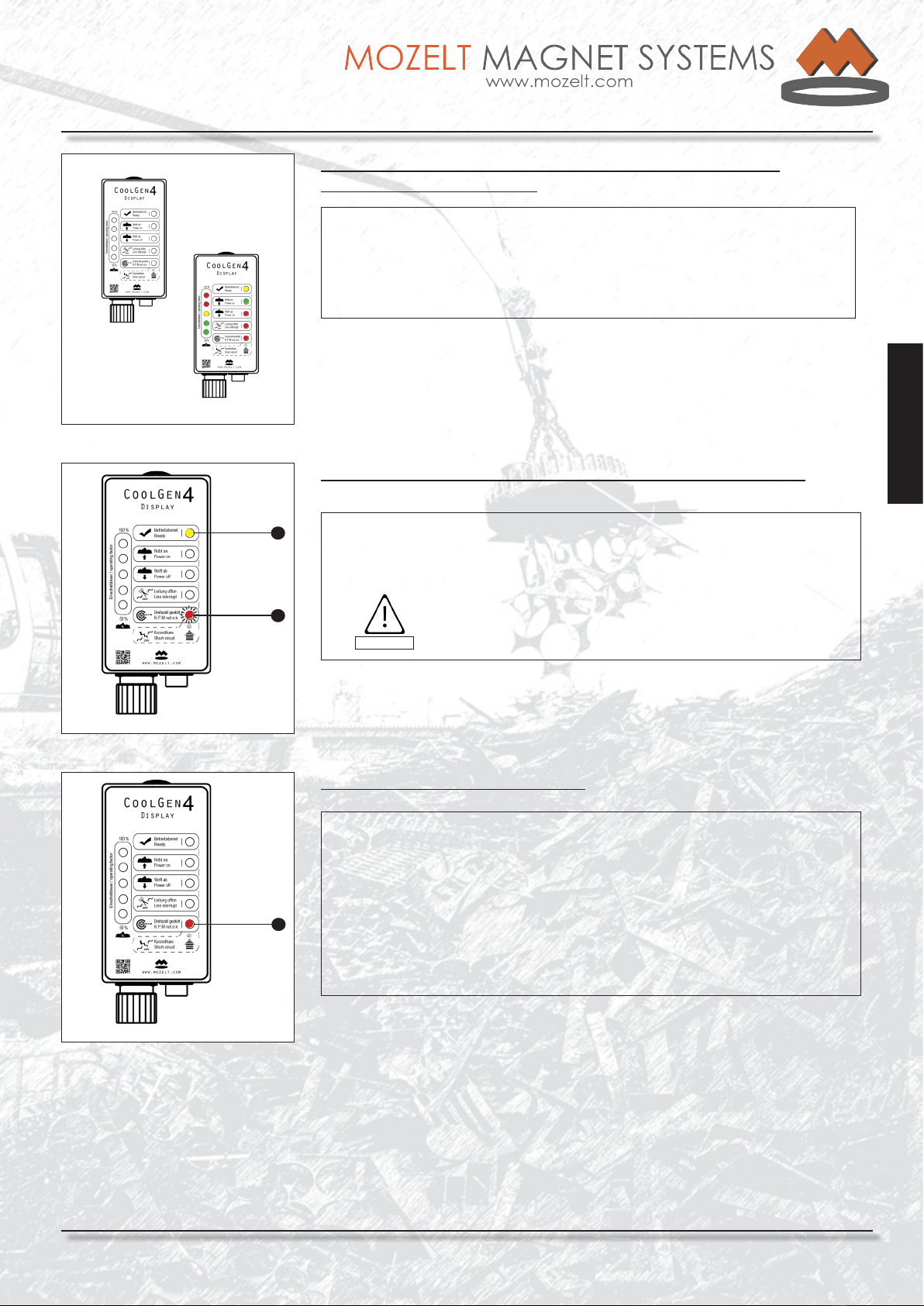
Fig.: 26 |MFD signals underspeed
Indicaon:
Possible cause:
Note:
only LED 5 (red), „R.P.M not o.k.“, possibly
also ashing.
The power generator runs at underspeed.
Have the speed checked!
LED 5 (steady light), speed of 1650 - 2000 rpm
LED 5 (ashing), speed of 2000 - 2350 rpm
5
1
Table of contents
Popular Inverter manuals by other brands

Mitsubishi Electric
Mitsubishi Electric FR-F820-00046 instruction manual

SolaX Power
SolaX Power X1 Series user manual

Mastervolt
Mastervolt Whisper 6 user manual

Orbio
Orbio 5000-Sc Operator's manual

AE Conversion
AE Conversion INV315-50EU Assembly and operating instructions

Generac Power Systems
Generac Power Systems Guardian 004188-1 owner's manual


