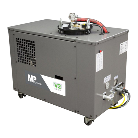
MP Systems R Series Instruction manual

MPSYSTEMS-M-001/06
MP SYSTEMS is committed to delivering quality products
and providing maximum productivity and uptime. Our
engineering team is diligent in eliminating high
maintenance issues associated with machine tool
accessories, to allow better performing equipment for your business.
Thanks to our quality components, dedicated engineers, sales team and manufacturing
personnel, MP SYSTEMS high pressure coolant systems & accessories are low
maintenance and longer lasting. MP SYSTEMS prides itself on building and supporting
a dependable product.
Our team works closely with CNC machine tool manufactures, distributors and
customers to provide excellent customer service. These relationships facilitate superior
application experiences. Our goal is to help make you more productive with less
downtime, decreased cycle times, improved tool life and more parts out the door.

MPSYSTEMS-M-001/06
R SERIES INSTALLATION, OPERATION, MAINTENANCE MANUAL
DOCUMENT PART #: B R OPERATOR
Revision Description Date
Issued Proofed
By:
00 Original 06/05/2014 S. Devlin
01 Updated all control signal
electrical drawings
Added Hydracell priming
instructions 12/24/2014 S. Devlin
02
Added low side visual
Super/Severe duty
schematics
RF20 mechanical/electrical
specifications
R Control schematic
R Signal schematic
Filter bag replacement diagram
Updated PLC settings for all R
Series
Recalculated kVA/FLA ratings
04/10/2015 S. Devlin
03
RV finish signal PLC
settings
Schematic corrections
Removed MP1200
installation
Added ‘how-to’ wire MP1200 in
line with flood pump
Added RC PLC settings 06/22/2015 S. Devlin
04
Removed pump specific
schematics
Updated format/style
Delivery check
Storage instructions
Control signal explanation
Added general rules
Added safety measure
Update electrical/mechanical
specifications
Transportation procedure
MP 1200 installation procedure
RC installation procedure
11/10/2016 S. Devlin
05
AC (Auto Cross) information
updated.
Updated Flow Diagrams
Electrical Specifications
Voltage Selection
VR Installation Options
Obsolete RC/CS 30
Added PLC Settings
MP1200 Installation Options
Mechanical Specifications
R/VR Control Schematics
Spare Parts List
05/7/2018 S. Devlin
06
Added fitting explanation for
generic kit
Added Ambient
Temperature Chart
Updated spare parts list
Updated FLA
Added VR10 info
Added relief valve ID page
Update RC and VR/VR2 PLC
Settings
Add CB kits for RFC/VRC
Updated mechanical Specs
Instructions for programming
variable pressure
Reformatted
Updated Logo
5/28/20 B. Backhaus
J. Bastiaanse

MPSYSTEMS-M-001/06
Contents
1. Introduction.........................................................................................................................1
1.1. Symbology....................................................................................................................1
2. Safety Measures.................................................................................................................2
2.1. General Rules...............................................................................................................3
2.2. Prevention of Mechanical Risks....................................................................................3
2.3. Prevention of Electrical Risks .......................................................................................3
3. Intended Uses.....................................................................................................................4
3.1. Features & Benefits ......................................................................................................5
4. Specifications......................................................................................................................6
4.1. Electrical Specifications................................................................................................7
4.2. Mechanical Specifications.............................................................................................8
4.2.1. Floor Layout...........................................................................................................9
4.3. Options & Accessories.........................................................................................11
5. Moving & Storage.............................................................................................................12
5.1. Delivery Checks..........................................................................................................12
5.2. Transport & Carriage ..................................................................................................12
5.3. Moving with a Fork Truck............................................................................................13
5.4. Storage.......................................................................................................................13
6. Installation.........................................................................................................................14
6.1. Installation Kit Components........................................................................................14
6.2. Recommended Tools for Installation...........................................................................14
6.3. Electrical Installation...................................................................................................15
6.3.1. Selecting Voltage .................................................................................................16
6.3.2. Power Harness Installation...................................................................................17
6.3.3. Control Signal Harness Installation ......................................................................18
6.4. Low Pressure Installation............................................................................................22
6.4.1. Low Pressure Hose Routing.................................................................................23
6.5. High Pressure Installation...........................................................................................24
6.5.1. Generic Mill Installation........................................................................................24
6.5.2. Generic Lathe Installation.....................................................................................25
6.5.3. 8JIC to 6JIS Fitting Explanation...........................................................................27
7. Operation..........................................................................................................................28
7.1. Filling & Priming..........................................................................................................28

MPSYSTEMS-M-001/06
7.2. Testing........................................................................................................................29
7.3. Start Up.......................................................................................................................29
7.4. Settings.......................................................................................................................30
7.4.1. R/R2 Series PLC Settings ....................................................................................31
7.4.2. Variable/Adaptive Series PLC Settings (VR Series).............................................33
7.4.3. Variable/Adaptive Series PLC Settings (VR2 Series)...........................................37
7.4.4. RA11 Series PLC Settings....................................................................................41
7.5. Alarms.........................................................................................................................43
7.6. Slow Fill Alarm ............................................................................................................44
8. Maintenance .....................................................................................................................45
8.1. Routine Maintenance..................................................................................................45
8.1.1. Filter Bag Replacement........................................................................................46
9. Options & Accessories......................................................................................................47
9.1. Auto Cross..................................................................................................................47
9.2. Dual Pressure .............................................................................................................47
9.3. Dual Simultaneous Pressure.......................................................................................47
9.4. Variable Pressure........................................................................................................48
9.4.1. How to Program Variable Pressure ......................................................................48
9.5. MP 1200 Mist Collector (MC)......................................................................................49
9.5.1. Control Signal Options (MC).................................................................................49
9.5.2. Plumbing Instructions (MC) ..................................................................................50
9.5.3. Understanding Gauge & Speed Control (MC) ......................................................51
9.6. RC Mountable Chiller (RC) .........................................................................................52
9.6.1. Chiller Ambient Temperature Chart......................................................................53
9.6.2. Mounting Instructions (RC)...................................................................................54
9.6.3. Plumbing Instructions (RC)...................................................................................55
9.6.4. Electrical Installation.............................................................................................56
9.6.5. Priming & Start-Up................................................................................................57
9.6.6. Settings (RC)........................................................................................................58
9.6.6.1. Settings (RC).....................................................................................................60
9.6.7. Alarms ‘RC’...........................................................................................................61
9.6.8. Maintenance (RC) ................................................................................................62
10. Spare Parts.......................................................................................................................64
10.1 Solenoid Identifier..........................................................................................................65
MPSYSTEMS-M-001/06
10.2 Relief Valve Identifier ....................................................................................................66
11. Hose Identification............................................................................................................67
11.1. Fitting Identification.....................................................................................................68
RF8 Series Flow Diagram........................................................................................................71
RFC Series Flow Diagram .......................................................................................................72
RA11 Series Flow Diagram......................................................................................................73
RT Series Flow Diagram..........................................................................................................74
RF16 Series Flow Diagram......................................................................................................75

1 MPSYSTEMS-M-001/06
1. Introduction
This manual contains instructions for installation, operation and maintenance of R Series
auxiliary coolant and chip control systems as well as indicating residual risk associated with them.
This manual has been specifically compiled and produced to enable easy and safe use by
appropriate personnel.
All associated rights, in particular the rights of reproduction, publication and translation, are
retained by the producer in accordance with authors rights.
MP SYSTEMS does not accept responsibility for any inaccuracies contained in this manual, whether
due to errors in printing or transcription.
It furthermore reserves the right to carry out such modifications to its products as it considers
necessary and/or useful, without compromising their essential characteristics.
MP SYSTEMS does not accept responsibility for improper use of the equipment,
unauthorized modifications to the same non-observance of the instructions contained in
the manual. The manual must be kept in a safe place and made available to personnel
qualified to use and maintain R Series auxiliary coolant and chip control systems.
1.1. Symbology
Symbology contained in this manual.
DANGER: Indicates possible danger. Failure to heed this warning carries a risk of
accident or injury.
DANGEROUS VOLTAGE: Indicates dangerous voltage. Failure to heed this warning
carries a risk of injury or death.
WARNING: Indicates a possible danger situation. Failure to heed this warning carries
a risk of injury.
INFORMATION: Indicates important information or advice on the use of the machine.
FLAMMABLE: Indicates possible flammable material.
LOCK-OUT/TAG-OUT: Lock-Out/Tag-Out R Series before service can be done.

2 MPSYSTEMS-M-001/06
2. Safety Measures
MP SYSTEMS disclaims all responsibility for non-observance of the instructions and advice
contained in this manual. It furthermore disclaims all responsibility for damage caused by improper or
inappropriate use of the machine or by modifications made without authorization.
These safety instructions contain all the general rules that must be observed during
commissioning, operations and all periods of attendance to the machine.
It is essential that these instructions are supplied and always available to the installer, competent
operators, and authorized maintenance personnel.
The following basic instructions must be observed when using the R Series;
Operation and maintenance must be carried out only by qualified personnel following the
instructions contained in this manual.
Always keep a copy of this manual near the machine.
Carry out routine maintenance operations with great care; have worn or damaged parts
replaced by qualified personnel and use original parts or those recommended by MP
SYSTEMS.
To function correctly and for operator security, the R Series must be operated with all panels in
place and secured.
Dangerous voltage contained within R Series; before carrying out any operations on R Series,
ensure that the electrical supply has been switched off.
Operating R Series with safety protection removed is strictly forbidden.
Before installing R Series ensure operating conditions are suitable for intended use.
MP SYSTEMS disclaims all responsibility for damage to person(s) or things resulting
from non-standard assembly of the machine or from re-use of its individual components.
Unauthorized replacement or removal of one or more parts of the machine is forbidden.

3 MPSYSTEMS-M-001/06
2.1. General Rules
R Series has been designed and constructed in such a way to minimize any possible cause of danger
to the operator and their surroundings. However, residual risk still remains and can arise through
improper use of the machine and can be of various types;
Risk due to escaped coolant/cutting fluid.
Risk due to excessive noise caused by operating outside permitted limits.
Risk of accidents caused by scraping against edged sheet metal profiles.
2.2. Prevention of Mechanical Risks
In operation, R Series contains some moving parts. These parts constitute a possible source of
danger to the operator, therefore in order to avoid any possible danger it is necessary to observe the
following operational rules;
Before removing any panels/guards, ensure electricity supply to the machine has been
switched off.
Never start R Series with any panel/guards removed.
The additives present in coolant/cutting fluid may have a corrosive action that can irritate the
skin and eyes.
oAlways wear gloves & eye protection when handling coolant/cutting fluid.
2.3. Prevention of Electrical Risks
When power to the machine is switched on, the machine is a source of danger, especially if the basic
safety rules are not followed. In order to avoid any possible danger it is necessary to observe the
following basic operation rules;
When making electrical connections to the R Series, observe state and federal electrical codes
or those otherwise in force. Observe the technical supply conditions imposed by the power
supply companies.
Before carrying out any work on the R Series, switch off the electrical supply at the main
isolator.
Work on the R Series must only be carried out by authorized personnel.
Always replace worn out or defective components.
Before working on electrical equipment always read the manual that contains the machines
circuit diagram.
Always make sure there is no electric power to the equipment.
Check to ensure the machine is earthed before powering on the R Series.
Check all electrical connections and connecting cables are well insulated and replace any
cables that are evidently worn or damaged.
Be sure to use power cables supplied by MP SYSTEMS or that have been approved by MP
SYSTEMS.

4 MPSYSTEMS-M-001/06
3. Intended Uses
MP SYSTEMS auxiliary coolant and chip control systems are constructed for use on milling
and turning machines that have existing coolant tanks, complete machining environment
enclosures, CNC controls with interlocks and low pressure pumps, typically referred to as flood
pumps.
MP SYSTEMS auxiliary coolant and chip control systems are intended to work alongside the
standard low pressure pump. The high pressures generated can dramatically improve tool life
and reduce cycle time, but should only be used where process improvements warrant its use.
MP SYSTEMS auxiliary coolant and chip control systems includes 2 large capacity filters. The
filters primarily protect the high pressure pump and the cutting tools present in the machine
tool. The presence of the 2 large capacity filters keeps the machine tool and its coolant much
cleaner.
MP SYSTEMS auxiliary coolant and chip control systems are intended for use with water
based coolants or oils with viscosities between 90 and 140 SUS @ 100° Fahrenheit.

5 MPSYSTEMS-M-001/06
3.1. Features & Benefits
When properly applied, high pressure coolant can considerably reduce cycle time, dramatically
improve tool life, and remove many of the requirements for operator intervention.
Cutting operations that suffer from chip evacuation problems can see improved speed,
accuracy, surface finish and reliability when using the R Series high pressure system.
In problem holes, high pressure can allow for higher speeds and higher feed rates, with little to
no pecking. This allows for 5-20% faster drilling.
Coolant fed reamers & boring tools, either through tool or close nozzle, can greatly improve
finish, tool life and accuracy.
In severe milling applications, the improvements will be easily recognized through the lack of
re-cutting of chips.
Heavy cuts can be made far more reliably with high pressure coolant. Tools that smoke or burn
will see tool life greatly improved. This allows for much ‘heavier’ cuts with tools that can be
pushed much harder, greatly improving cycle times.
Jobs already being run with ‘flood’ coolant will see dramatic increase in productivity with high
pressure coolant.
Often, time consuming programing methods such as rough/finish cuts, interrupted feed, non-
optimum tool and feed speeds can be eliminated with the use of high pressure coolant. High
pressure coolant gives the ability to break and/or control the chips that typically cause slow
speeds.
Rings of material left on drills and boring bars can be blown off with high pressure coolant.
Coolant through sub spindle can eliminate improper chucking and reduce parts being marked
by chips left in the collet.

6 MPSYSTEMS-M-001/06
4. Specifications
MP SYSTEMS equipment ships with an identification label. The label is located by the main
disconnect on the front of the machine.
Information listed on Identification Label;
Pump Type
Serial Number
Build Date
Operating Voltage (208-230VAC/460VAC)
FLA (Full load Amps). Largest load, for determining power service requirements.
The operating voltage may be changed in the field if necessary. Changing the operating
voltage can only be done by specialized personnel. Not available on all systems.
*All specifications are subject to change.

7 MPSYSTEMS-M-001/06
4.1. Electrical Specifications
MODEL FLA @ 208/230VAC
(STANDARD VAC) FLA @ 460VAC kVA
RF8 / VR8 23.8-22.4 11.2 9
RF CE / VR CE (200/400V) 28 @ 200 14 @ 400 10
RFO5 24.9 11.75 9
RFC8 / VRC8 38.8-37.4 19.2 14
RA11 35 16 13
RAC11 50 24 18
RT / VRT 48 23 18
RF16 / VR16
RTC 63 31 23
RFC16
VR10 56 27 20
VR20 48 23 18
VRT40 N/A 38 30
RT40
Mountable Chillers
RC36 11.5 6.3 8
*Approximate FLA values. All electrical specifications are subject to change.
Component/Accessory HP RPM FLA @ 208/230VAC FLA @ 460VAC
High Pressure (Primary/Secondary)
7.5 1750 19.8-18.4 9.2
High Pressure VR40
(Primary/Secondary)15 1750 N/A 19
High Pressure VR20
(Primary) 20 1800 N/A 25
High Pressure RT30/VRT30
(Primary/Secondary) 20 1800 N/A 25
High Pressure VR10 20 1450 N/A 25
High Pressure
(Secondary)
*RA11 Only 2.0 1750 6.2-6 3
Feed/Supply Pump
*StandardRC36 1.0 3450 4 2
Feed/Supply Pump
*VR20 Only 1.5 3450 4.6-4.5 2.25
Feed/Supply Pump
*VRT40/RT40 Only 2.0 3450 6 4
Heat Exchanger (HX)
1/3 3425 1.1 0.55
MP1200 Mist Collector (MC)
2 N/A 5 3

8 MPSYSTEMS-M-001/06
Control Power Control Signals Alarm Circuit
150VAC Transformer 24VDC NC
110VAC Secondary NO
Primary Fused
4.2. Mechanical Specifications
5. MODEL LENGTH
(in) WIDTH
(in) HEIGHT
(in) CAPACITY
(gal) WEIGHT
(lbs)
VR8 36 28 42 50 800
RF8
RA11 36 28 42 50 900
VR16
42 38 42 70 1250
VRT
RF16
RT
VR20 42 38 42 70 1315
VRT40 52 49 53 80 2000
RT40
Accessories
RC36 39 26 23 N/A 450
MP1200 24 25 40 N/A 400
*Approximate values. All mechanical specifications are subject to change.
MODEL OUTPUT PRESSURE VARIABLE
PRESSURE FLOW RATE
Motor 1 Motor 2
VR8 250-1000 PSI 8 GPM N/A
RF8 250-1000 PSI 8 GPM N/A
RA11 (Adaptive Flow Rate) 250-1000 PSI 8 GPM 3 GPM
3,8 or 11 GPM Total
VR16 250-1000 PSI 16 GPM Total
VRT 8 GPM 8 GPM
RF16 250-1000 PSI 16 GPM Total
RT 8 GPM 8 GPM
VR10 500-3000 PSI 10 GPM N/A
VR20 250-1000 PSI 20 GPM N/A
VRT40 250-1500 PSI 20 GPM 20 GPM
RT40 250-1500 PSI 20 GPM 20 GPM

9 MPSYSTEMS-M-001/06
4.2.1. Floor Layout
R / VR SERIES
28”
36”
15” – 24”

10 MPSYSTEMS-M-001/06
RF16 / RT / VR16 / VRT SERIES
15” – 24”
38”
42”

11 MPSYSTEMS-M-001/06
4.3. Options & Accessories
ABRV. NAME DESCRIPTION
AC Auto Cross
System automatically switches between the two filter vessels present
in unit. Once a filter bag becomes depleted, the AC system senses the
lack of flow and will switch to the clean filter. PLC will display depleted
filter #.
DP Dual Pressure Allows for 2 set pressures that can be controlled using M-Codes.
Primary pressure 1000psi, Secondary pressure 500psi.
DSP Dual
Simultaneous
Pressure
Each port has set pressure. Port 1 & Port 2 can run at set pressure
simultaneously.
Port 1 1000psi - Port 2 500psi
MC MP1200
Mist Collector Can be mounted on top of R Series or mount directly to machine tool.
Removes mist from machine tool cabinet.
HX Heat Exchanger Removes heat from oil using ambient air temperature.
RC Mountable
Chiller Cools fluid using refrigerant, allows for greater fluid temperature
control.

12 MPSYSTEMS-M-001/06
5. Moving & Storage
5.1. Delivery Checks
When taking delivery of machine, carefully check the
physical condition of the packaging. Having removed
the packaging, check that the machine has not
suffered any knocks or damage. Check that the
machine has been transported in the correct position.
In case of damage, do not accept the goods and
immediately inform MP SYSTEMS.
DO NOT accept the machine in the event of irregularities during transit. The hauler will bear the full
responsibility for any damage suffered.
5.2. Transport & Carriage
The machine must be transported in a vertical position (casters/wheels down). Machine tank MUST
BE EMPTY before moving. R Series has been constructed so, as to be moved by fork truck or rolled
around on casters on base of unit.
The machine must be moved in such a way as to avoid the risk of damage.
Do not attempt to lift the machine with equipment that is inadequate or unsuitable, especially with
equipment that is too small for overall weight of machine. Refer to Section 4.2. Mechanical
Specifications for unit weight.
Before moving machine, take care to ensure that all removable panels are firmly attached to the unit
to prevent them from falling.
WARNING: Do not transport machine with fluid in tank.

13 MPSYSTEMS-M-001/06
5.3. Moving with a Fork Truck
To move the machine with a fork truck, the two blades must be
inserted under the long side of the machine. The base is
designed for transportation by fork truck. Insert blades
symmetrically with respect to the center of gravity of the
machine, and push them in through the whole depth of the
machine. Lifting can then be carried out. Carry out the moving
operation at a very slow speed.
Ensure the tank is completely empty of coolant when moving.
5.4. Storage
The R Series must be stored in a cool and dry environment,
avoiding all extreme conditions. Avoid freezing conditions. All
coolant must be drained from machine before being stored. If
utilizing water based coolants, the system must be flushed
before storage, please refer to coolant manufacture for correct
flushing agent. Removing all coolant from the system will
ensure coolant does not become contaminated while in the
system. Contaminated coolant may lead to malfunctions.
Not properly draining/flushing R Series before storage can lead to jammed solenoids,
diaphragms that become stuck and bacterial growth. Bacterial growth will contaminate
any coolant it comes in contact with. Contaminated coolants effectiveness is also greatly
reduced.

14 MPSYSTEMS-M-001/06
6. Installation
All MP SYSTEMS, R Series are shipped on wooden pallets designed for the safe transport of the R
Series auxiliary coolant and chip control system. A large MP SYSTEMS container protects the R
Series from any unnecessary damage during transportation.
6.1. Installation Kit Components
COMPONENT QUANTITY/LENGTH
Power Harness 1
Control Signal Harness 1
Jumper Plug for Signal Harness 1
Spare 5 Micron Filter Bag 2
Operation & Installation Manual 1
Inlet Dip Tube 1
Return Dip Tube 1
1 1/4" Diameter Inlet Hose 14’
1 1/4" Diameter Return Hose 14’
2” Hose Clamp 4
Weld Clamp (Mounting Dip Tubes) 2
Self-Taping Hex Screws (Mounting Weld Clamps) 2
Machine Tool Specific Installation Components 1
6.2. Recommended Tools for Installation
Philips (Cross) Head Screwdriver
Flat Blade Screwdriver
Electric Drill
7/8” UniBit (Step Drill)
1 1/4" Conduit Punch or equivalent size hole saw
12” Pipe Wrench (Minimum)
Metric Hex Keys
Teflon Pipe Tape / Liquid Pipe Sealant
This manual suits for next models
24
Table of contents
Other MP Systems Chiller manuals
Popular Chiller manuals by other brands

Hydro Tek
Hydro Tek Active Aqua Chiller, 1/10 HP instructions

Trane
Trane RTAD 085 Installation operation & maintenance

York
York YK installation instructions

HURAKAN
HURAKAN HKN-BCF5M manual

SMC Networks
SMC Networks HRR012-A*-20 Series operating manual

Carrier
Carrier AquaEdge 19XR series Start-up, operation and maintenance instructions

Nordcap
Nordcap SKF 20 GN 1/1 Installation

Pfannenberg
Pfannenberg PC2500 WT CE STD Operating and maintenance instructions

Elkay
Elkay HRC2-10-1D installation instructions

Amada
Amada LP1173173 Operation manual

SMC Networks
SMC Networks HRS090-A...-20 Series Original instructions

Castel MAC
Castel MAC T3 user guide