MP Systems Cyclonic Debris Removal Series Owner's manual

MP Systems - 34 Bradley Park Road, East Granby, CT 06026 USA - Phone + 1 (877)-689-1860 - Email mpteam@mp-systems.net
INSTALLATION, OPERATION, & MAINTENANCE MANUAL
Cyclonic Debris Removal Series
Pump Serial Number: ________________
Date: 7/28/2022
Revision: 06
MP SYSTEMS is committed to delivering quality
products and providing maximum productivity and
uptime. Our engineering team is diligent in
eliminating high maintenance issues associated
with machine tool accessories, to allow better
performing equipment for your business.
Thanks to our quality components, dedicated engineers, sales team and
manufacturing personnel, MP SYSTEMS high pressure coolant systems &
accessories are low maintenance and longer lasting. MP SYSTEMS prides itself on
building and supporting a dependable product.
Our team works closely with CNC machine tool manufactures, distributors and
customers to provide excellent customer service. These relationships facilitate
superior application experiences. Our goal is to help make you more productive with
less downtime, decreased cycle times, improved tool life and more parts out the
door.

CDR SERIES INSTALLATION, OPERATION, MAINTENANCE MANUAL
DOCUMENT PART #: B CDR OPERATOR
Revision
Description
Date Issued
Author
01
Original
8/25/2020
K. Quintin
02
•Updated for production model.
1/25/2021
K. Quintin
03
•Added quick start guide components,
•updated with more information.
4/26/2021
K. Quintin
04
•Updated quick start guide and install info
•Updated start/stop mode of operation
•Updated PLC settings
2/23/2022
K. Quintin
05
•Updated quick start guide and install info
•Updated PLC screens
•Added “Severe Duty” components
6/14/2022
K. Quintin
06
•Updated “Severe Duty”section
7/28/2022
K. Quintin


Table of Contents
1. Introduction .................................................................................................................. 3
1.1. Symbology .............................................................................................................4
2. Safety Measures.......................................................................................................... 5
2.1. General Rules........................................................................................................6
2.2. Prevention of Mechanical Risks.............................................................................6
2.3. Prevention of Electrical Risks.................................................................................6
3. Intended Uses.............................................................................................................. 7
3.1. Features & Benefits................................................................................................8
3.2. Considerations and Explanations...........................................................................9
4. Specifications............................................................................................................. 12
4.1 Electrical Specifications...........................................................................................12
4.2 Mechanical Specifications .......................................................................................13
4.3 Floor Layout.........................................................................................................14
5. Moving & Storage.......................................................................................................... 16
5.1 Delivery Checks.......................................................................................................16
5.2 Transport & Carriage...............................................................................................16
5.3 Storage....................................................................................................................16
6. Installation..................................................................................................................... 17
6.1 Install Kit Components.............................................................................................19
6.2 Recommended Tools for Installation .......................................................................20
6.3 Electrical Installation................................................................................................22
6.3.1 Selecting Voltage...........................................................................................22
6.3.2 Power Harness Installation............................................................................23
6.3.3 Control Signal Installation (Optional-Not Required)...........................................24
6.4 Plumbing Installation................................................................................................25
6.4.1 Dip Tubes Installation........................................................................................25
6.4.2 Hoses and Clamps Installation..........................................................................28
6.4.3 Pump Priming Procedure..................................................................................30
7. Operation ...................................................................................................................... 31
7.1 Start Up Checklist....................................................................................................31

7.2 Set Mode of Operation.............................................................................................33
7.3 PLC & Alarm Displays..........................................................................................34
7.4 PLC Settings........................................................................................................35
8. Maintenance .............................................................................................................. 39
9. Spare Parts................................................................................................................ 40
10. Warranty Information.................................................................................................. 41

1. Introduction
This manual contains instructions for installation, operation, and maintenance of the
CDR Cyclonic Debris Removal System, as well as indicating residual risk associated with
it. This manual has been specifically compiled and produced to enable easy and safe use
by appropriate personnel.
All associated rights, in particular the rights of reproduction, publication, and
translation, are retained by the producer in accordance with authors rights.
MP SYSTEMS does not accept responsibility for any inaccuracies contained in this
manual, whether due to errors in printing or transcription. It furthermore reserves the right
to carry out such modifications to its products as it considers necessary and/or useful,
without compromising their essential characteristics.
MP SYSTEMS does not accept responsibility for improper use of the equipment,
unauthorized modifications, or non-observance of the instructions contained in the
manual. This manual must be kept in a safe place and made available to personnel
qualified to use and maintain CDR Systems.

1.1. Symbology
Symbology contained in this manual.
DANGER: Indicates possible danger. Failure to heed this warning carries a
risk of accident or injury.
DANGEROUS VOLTAGE: Indicates dangerous voltage. Failure to heed this
warning carries a risk of injury or death.
WARNING: Indicates a possible danger situation. Failure to heed this
warning carries a risk of injury.
INFORMATION: Indicates important information or advice on the use of the
machine.
FLAMMABLE: Indicates possible flammable material.
LOCK-OUT/TAG-OUT: Lock-Out/Tag-Out CDR Series before service can be
done.

2. Safety Measures
MP SYSTEMS disclaims all responsibility for non-observance of the instructions
and advice contained in this manual. It furthermore disclaims all responsibility for
damage caused by improper or inappropriate use of the machine or by modifications
made without authorization.
These safety instructions contain all the general rules that must be
observed during commissioning, operations, and all periods of attendance to
the machine.
It is essential that these instructions are supplied and always available to the
installer, competent operators, and authorized maintenance personnel.
The following basic instructions must be observed when using the CDR Series:
•Operation and maintenance must be carried out only by qualified personnel
following the instructions contained in this manual.
•Always keep a copy of this manual near the machine.
•Carry out routine maintenance operations with great care; have worn or
damaged parts replaced by qualified personnel and use original parts or
those recommended by MP SYSTEMS.
•To function correctly, and for operator security, the CDR Series must be
operated with all panels in place and secured.
•Dangerous voltage contained within CDR Series. Before carrying out any
operations on CDR Series, ensure that the electrical supply has been
switched off.
•Operating CDR Series with safety protection removed is strictly forbidden.
•Before installing CDR Series ensure operating conditions are suitable for
intended use.
MP SYSTEMS disclaims all responsibility for damage to person(s) or
things resulting from non-standard assembly of the machine or from re-
use of its individual components. Unauthorized replacement or removal
of one or more parts of the machine is forbidden.

2.1. General Rules
The CDR Series has been designed and constructed in such a way to minimize any
possible cause of danger to the operator and their surroundings. However, residual risk
remains and can arise through improper use of the machine and can be of various
types:
•Risk due to escaped coolant/cutting fluid.
•Risk due to excessive noise caused by operating outside permitted limits.
•Risk of accidents caused by scraping against edged sheet metal profiles.
2.2. Prevention of Mechanical Risks
In operation, the CDR Series contains some moving parts. These parts constitute a
possible source of danger to the operator, therefore to avoid any possible danger it is
necessary to observe the following operational rules:
•Before removing any panels/guards, ensure electrical supply to the machine
has been switched off.
•Never start the CDR Series with any panel/guards removed.
•The additives present in coolant/cutting fluid may have a corrosive action
that can irritate the skin and eyes.
oAlways wear gloves & eye protection when handling coolant/cutting
fluid.
2.3. Prevention of Electrical Risks
When power to the machine is switched on, the machine is a source of danger,
especially if the basic safety rules are not followed. To avoid any possible danger, it is
necessary to observe the following basic operation rules:
•When making electrical connections to the CDR Series, observe state and
federal electrical codes or those otherwise in force. Observe the technical &
electrical supply conditions imposed by the power supply companies.
•Before carrying out any work on the CDR Series, switch off the electrical
supply at the main isolator.
•Work on the CDR Series must only be carried out by authorized personnel.
•Always replace worn out or defective components.
•Before working on electrical equipment always read the manual that
contains the machines circuit diagram.
•Always make sure there is no electric power to the equipment.
•Check to ensure the machine is earthed before powering on the CDR
Series.
•Check all electrical connections and connecting cables are well insulated
and replace any cables that are evidently worn or damaged.
•Be sure to use power cables supplied by MP SYSTEMS or that have been
approved by MP SYSTEMS.
3. Intended Uses
The CDR is a proven effective solution for high volume, multiple shift machining
applications with a filtering conveyor. It provides constant, full flow coolant filtration to
catch and prevent fines from accumulating in the machine’s coolant tank, where they
contaminate the entire coolant system and machining environment. This buildup
eventually takes away from valuable coolant volume and requires frequent cleanouts and
shutdowns.
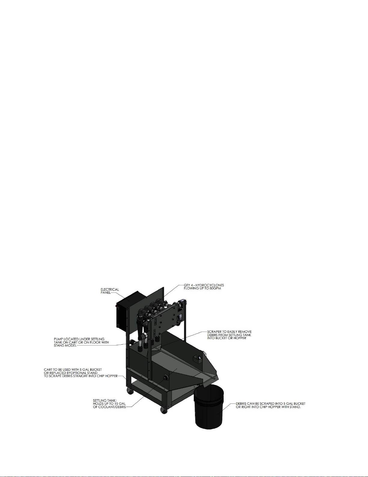
The pump picks up the dirty coolant as it enters the tank after a conveyor and
pumps it through a carefully engineered hydro-cyclone configuration at 80 gallons per
minute. It then deposits a concentrated slurry into an easily cleanable settling tank below
and allows clean coolant to return to the machine tool tank. When the CDR settling tank is
full, simply scrape out the debris into a bucket or chip hopper without having to interrupt
production.
•The CDR is designed for applications with the following criteria
oHigh production, high volume machining
oRunning Multiple shifts
oHas a filtering conveyor
oWill have a debris/sludge buildup in coolant problem
•Typical types of machines the CDR can benefit greatly
oHorizontal Machining Centers
oVertical Machining Centers
oAutomated production lines
oAfter filtering conveyors with a rating of 500μm or lower
3.1. Features & Benefits
CDR Features:
▪80 GPM (gallons per minute) constant flow rate
▪Filtration down to 3um (depending on density)
▪Full flow filtration system to circulate coolant in tank.
▪Quick and convenient cleanout
▪Easy Installation with complete parts kit
▪Status Indicator light and HMI Screen
▪3 Phase breaker and wiring kit to easily pull power from machine.
▪Auto start on power up feature or scheduled clock run function
▪Hour counters for filter run time vs machine run time (optional)
▪Cleanable pre-filter
▪Low Maintenance
▪2 Year Parts Warranty*
CDR Benefits:
▪Clean coolant lasts significantly longer
▪Less wear & tear on machine and components
▪Greatly extend time between tank cleanouts
▪Prevent unexpected coolant related shutdowns
▪Overall cleaner machining environment
▪Improved part quality
▪Improved tool life
▪Improved pump wear components life

3.2. Considerations and Explanations
•The CDR is not intended to be a replacement for filtering conveyors and is not to be
used after a standard hinge belt conveyor.
•The CDR is intended to be used after the following filtering conveyor styles. Drum,
disc, filter box, and in certain applications, magnetic conveyors.
•A filtering conveyor is a conveyor with a filtration rating of 500μm (micron) or lower.
Common examples are the Mayfran Consep 2000 or similar, and LNS MH250 or
MH500 or similar.
•The CDR is intended for machines running water-based coolants only. It does not
work with oil applications. A purge would be recommended for oil applications.
•High volume machining centers running multiple shifts should get a filtering
conveyor.
oA shift is considered 2000 hours/year, 2 Shifts would be 4000 hours/year, etc
•The CDR is intended to filter out fines/debris smaller than 1/32” (thickness of a
credit card)
oAn easy way to determine this is to take a reasonably sized sample of chips
from the coolant tank right after the conveyor, dry them out, and lay on a
piece of paper next to a steel rule with graduations of 1/32”. Individual
chips/grains should not exceed 1/32”
•The CDR is not intended to pick up or filter large chips. Large chips tend to settle to
the bottom of the tank rapidly and once the debris begins to pile up, it will stay there
until manually removed. Particles must stay in suspension long enough to get
sucked up by the pump.
•The CDR does a great job at capturing and filtering “snow” like debris that spreads
evenly throughout the machine tank.
•The CDR is for use with materials that have a specific gravity of 2x water or higher,
or a density 2g/cm^3 or higher. (Cast Iron, Aluminum, Steel, Alloys)
•The CDR does not work well with plastics or composites. A purge would be
recommended for plastics or composites applications.
•The CDR is typically located alongside the machine’s coolant tank where space will
allow. 15’ length hoses are provided to allow for positioning the CDR system where
it makes the most sense.
•Machine’s producing less than 10 gallons of debris a month can typically use the 5-
gallon bucket to dispose of the debris in the CDR settling tank.
•Machines with higher debris loads can purchase taller legs and mounting pads to
position the settling tank higher up to allow them to scrape the debris from the
settling tank right into their chip hopper.
•The tank must be configured to allow proper circulation to ensure that a high
percentage of debris is removed over time and the tank eventually reaches an
equilibrium of debris being deposited, to debris being removed, maintaining an
acceptable PPM in the machine’s coolant tank.
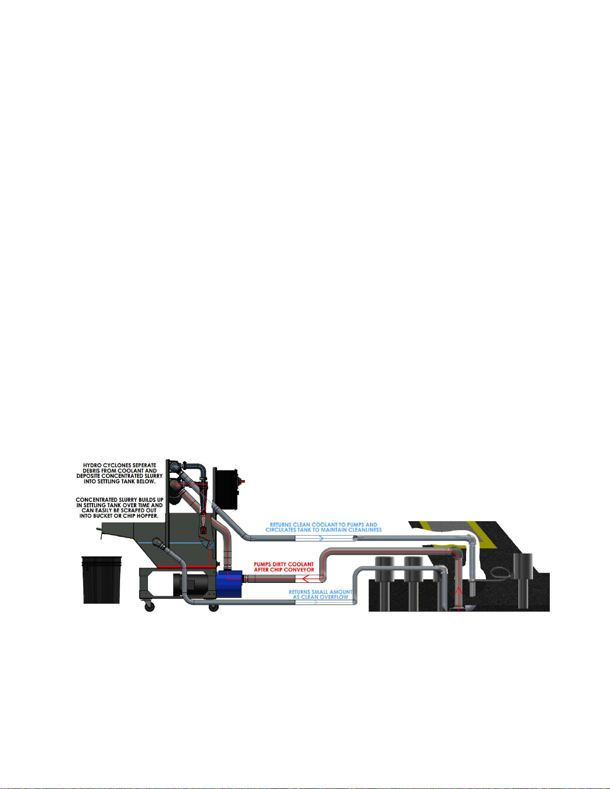
•Hydro cyclones work based on centrifugal forces separating the denser debris from
the lighter fluid and concentrating that debris into the discharge area while the
lighter fluid is carried back through the return to tank.

oThe high fluid velocities create high centrifugal forces that “pull” the denser
particles towards the walls of the cyclone cone. The velocity and forces
increase as the cone narrows towards the bottom. The heavier concentrated
debris is discharged through the bottom apex. The lighter fluid exits the top
of the cyclone via the vortex finder and returns to the machine coolant tank.
•The CDR uses polypropylene hydrocyclones with ceramic apex cones for abrasion
resistance.
•Performance on this type of technology is rated by the D50 cutoff point.
oD50 cutoff means depending on several variables, 50% of the debris of a
certain size will be removed from the coolant and report to the settling tank,
while the other 50% of the debris will return back to the tank to be circulated
and filtered again.
•Cyclonic filtration works on the idea that the coolant will be constantly circulated
and re-filtered every time is passes through the CDR.
oExample, each time coolant passes through the cyclones, 50% of 5μm
particles are removed. The remaining 50% is then recirculated through the
tank and filtered again, removing 50% of it, and thus returning 25% of the
initial debris back to tank. On the 3rd pass, it will return 12.5% and so on.
•The CDR has a flowrate of 80 GPM, meaning it can circulate and filter tanks at a
quick rate. Examples are as follows.
oTank = 80 gallons, CDR is 80GPM, tank is circulated once every 1 minute.
oTank = 100 gallons, CDR is 80GPM, tank is circulated once every 1 min 15
sec.
oTank = 200 Gallons, CDR is 80GPM, tank is circulated once every 2 min 30
sec.
•The system should always be on and filtering when machining. There are several
ways to run the filter system, most do not require any additional wiring. Factory
settings are to start/stop the CDR by pressing the buttons on the HMI display. A
setting can also be enabled to allow the CDR to run automatically when powered
up. Another option is to run the filter on a scheduled Real time clock timer. Refer
to the quick start guide and PLC settings section for more information.
•The alarm circuit interface with the machine is not typically required but is available
if desired. Typically, customers will rely on the status indicator light on the control
box to tell them when the CDR requires maintenance. This works for most
customers but if wanted, an alarm signal can be interfaced with the machine tool.
Refer to the interface drawing for more explanation.
•For machines currently running, there is a quick way to determine debris load that
accumulates in the tank so it can be compared to how much debris is removed by
the filter over time. Carefully vacuum only the liquid coolant from one corner of the
tank and leave all sludge and debris remaining in the tank. Take several
measurements around the tank of how deep the layer of sludge is. Calculate the
average level. Calculate the volume of debris by measuring the area of tank and
multiplying by the average height of the debris. If measuring in “inches”, then divide
the total area of cubic inches by 231 to calculate total gallons of debris in the tank.
Then simply divide the number of gallons by the number of days it took to
accumulate. This will result in “X” gallons per day of material deposited into the

machine tank. This number can then be compared to the number of gallons that
are removed by the filter daily.
•Severe Duty models use an additional filter vessel containing a perforated screen
basket that can be manually emptied, cleaned, and re-used. The purpose of this
vessel is to capture particles larger than 1/16”that would normally be automatically
removed by a filtering conveyor. The basket will hold up to 1.5 gallons of chips
before it needs to be emptied.
•Be sure to inspect conveyor filter(s) before installing CDR. Wearing appropriate
gloves or using a scoop, take a sample of debris from the machine tank, dry
through a coffee filter, and spread out across a piece of paper. There should be no
individual particles larger than 1/32” (the thickness of a credit card). If there is, this
indicates a tear in the filter screen, or the screen(s) are plugged, and the coolant
level in conveyor is piling up too high and debris is bypassing the conveyor. These
issues will need to be addressed before adding secondary filtration. A properly
working filtering conveyor is the best way to automatically remove a large amount of
the chips being produced by most machining operations.
•CDR typical installation time required: 4 Hours
•A full installation kit is provided to adapt to most tank configurations.
•Low pressure plumbing kit includes inlet, return, and overflow dip tubes, hoses, and
clamps.
•3 Phase power kit w/circuit breaker provided to pull power directly from machine.
•CDR can be set to automatically run when powered on, or with scheduled run clock.
•Status indicator light and HMI screen removes need for alarm interface with
machine.
•May require hole saws to modify tank, see appendix in back for more information.
•The CDR requires roughly 24” x 48” of floor space that is located next to the coolant
tank.
•The Severe Duty “SD” model requires roughly 34” x 50” of floor space to include
filter.

4. Specifications
*All specifications are subject to change.
All MP Systems equipment ships with identification label. The label is located by main
disconnect on front of the system.
The label contains
•Pump Type
•Serial Number
•Build Date
•Operating voltage (208-230VAC) (optional 480V)
•FLA/ Largest Load for determining power service requirements
4.1 Electrical Specifications
All power for motors and hydraulics is derived from CDR Series power input source.
Main Power: 3 Phase @ 60Hz
Model
FLA @
208-230 VAC
FLA @
480 VAC
kVA
CDR80
8.5*
4.0*
3.2
Motor
HP
RPM
208-230 VAC
460 VAC
Feed Pump
3
3450
8.5A
4.0
Control Power
Control Signal
Alarm Circuit
208-230 VAC
24vdc
NC (Normally Closed)
NO (Normally Open)

4.2 Mechanical Specifications
5. Model
CDR80
CDR80 SD
Flow Rate
80 GPM
80 GPM
Length
48”
50”
Width
24”
34”
Height
48” (Standard), 66” (Tall)
48” (Standard), 66” (Tall)
Weight
500 lbs
650lbs
Capacity
15 gal (settling tank)
15 gal (settling tank) 5 gal (filter tank)
Filter
Volume
Dimensions
Rating
Y Strainer
Screen
38 in^3
2 5/8” x 7”
12 Mesh (1/16”)
“SD” Extra
Capacity
Vessel
365 in^3
(1.5 gallons)
#1 Size Basket
6.5” X 11”
12 Mesh (1/16”)
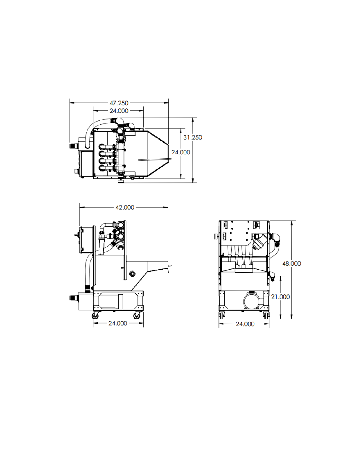
4.3 Floor Layout
Standard CDR Dimensions

“Severe Duty” Models Only – Extra Capacity Pre-Filter Dimensions

5. Moving & Storage
5.1 Delivery Checks
When taking delivery of a machine, ensure that the
machine has been transported in the correct position.
Carefully check the physical condition of the box for
any signs of external damage. If there is evidence of
damage, remove the packaging to ensure there is no
damage to the contents of the skid. In case of
damage, DO NOT accept the goods and
immediately inform MP SYSTEMS. If you are unsure if
there is damage to the contents and accept delivery, you must write “Damaged” on the
delivery receipt. In the event of irregularities during transit, the freight company will bear
the full responsibility for any damage suffered.
5.2 Transport & Carriage
The machine must be transported in a vertical position, as shipped. The tank MUST BE
EMPTY before moving. The CDR Series has been constructed to be moved by fork truck.
The machine must be moved in such a way as to avoid the risk of damage. Do not
attempt to lift the machine with equipment that is inadequate or unsuitable, especially with
equipment that is too small for overall weight of machine. Refer to Section 4.2.
Mechanical Specifications for unit weight. Only trained and licensed Fork Truck
operators may transport this machine. MP SYSTEMS is not responsible for any damage
caused by unauthorized use.
WARNING: Do not transport machine with fluid in tank.
5.3 Storage
The CDR Series must be stored in a cool and dry environment, avoiding
all extreme conditions including freezing conditions. All coolant must be
drained from machine before being stored. If utilizing water-based
coolants, the system must be flushed before storage, please refer to the
coolant manufacturer for correct flushing agent. Removing all coolant
from the system will ensure coolant does not become contaminated while in the system.
Contaminated coolant may lead to malfunctions.
Not properly draining/flushing CDR Series before storage can lead to bacterial
growth, which will contaminate any coolant it comes into contact with.
Contaminated coolants effectiveness is also greatly reduced.
This manual suits for next models
2
Table of contents


