MPI TS200-SE User manual

MPI TS200-SE
200 mm Manual Probe System
User Manual


3
IMPORTANT NOTICE OF USE
PREFACE
SAFETY NOTICE
1. This manual is copyrighted with all rights reserved. Under the copyright laws, this
manual may not be copied or modied in whole or part, without the written consent
of the publisher.
2. Parts of this manual are subject to change without prior notice.
3. We welcome any comments on ambiguities, errors, omissions, or missing pages.
4. Never attempt any procedure on the MPI TS200-SE probe system that is not specially
described in this manual. Unauthorized operation can cause faults or accidents. MPI
Corporation is not liable for any problems resulting from unauthorized operation of the
equipment.
In this manual, safety instructions are preceded by the symbol . Always read and fol-
low the instructions before performing the required procedures. Informational notes are
preceded by the symbol . It indicates important information about the product.
Thank you for purchasing the TS200-SE probe system. This user manual is intended for
users who are using the probe system for the first time. It provides all necessary informati-
on about the overview, unpacking and installation procedures, operation and maintenance
of the system.
The information in this manual will help users to have a safer and more efficient operation
of the probe system. Any nonconformity from the proposed operation or any modification
of use which the probe system is not intended may results in a hazardous and not efficient
operation scenario or situation. MPI Corporation renounces any claim of responsibilities for
any consequences resulting from any alteration and nonconformity from intended use of
the system.
Please consult our MPI technical support team or our service representative if you are un-
sure of using the equipment.
User Manual-MPI-TS200-SE-UG REV 1.1.0 -19122017

4
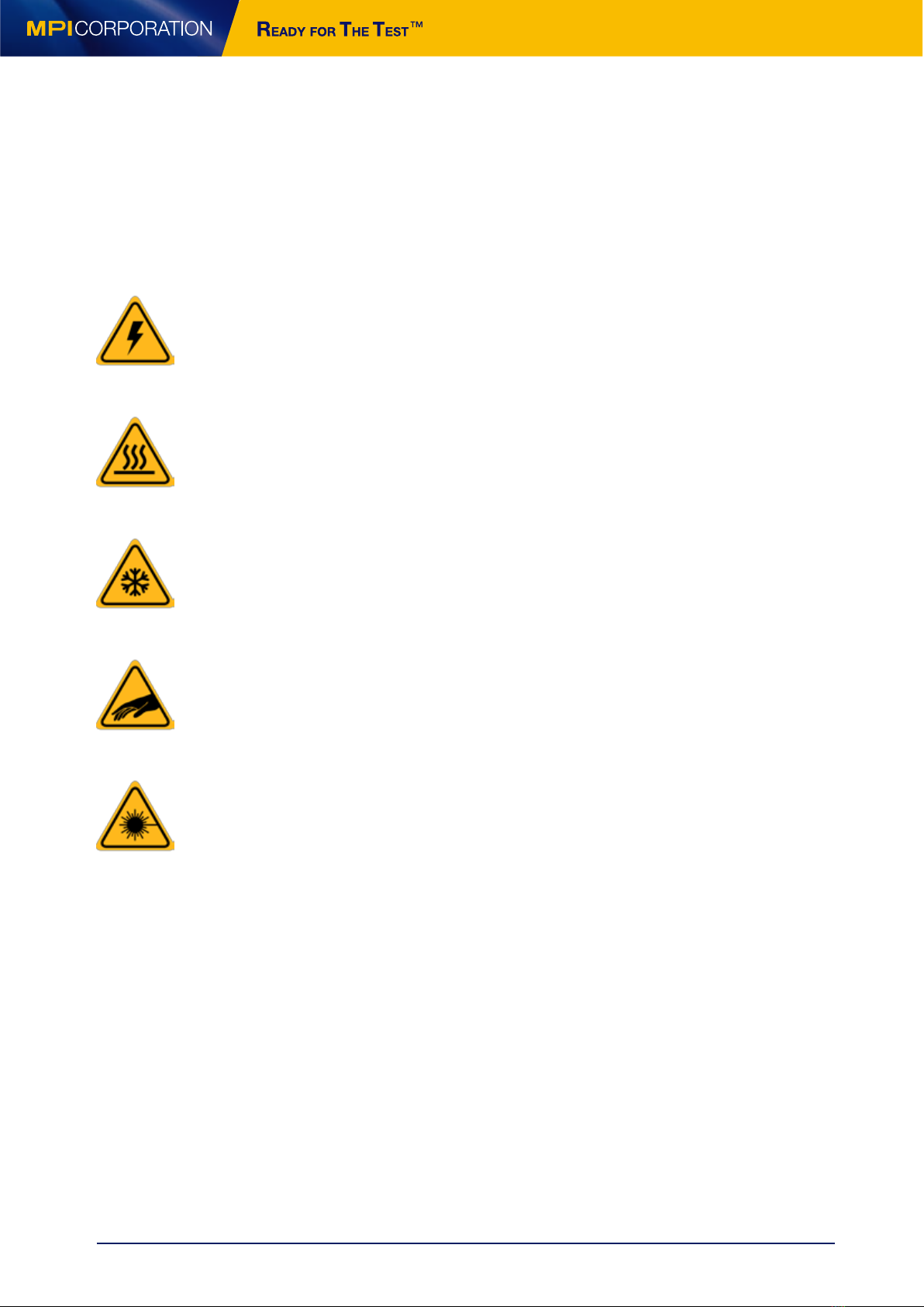
CAUTION! : Electronic Shock! Danger of Operation!
Do not touch during operation. Danger of electric shock or burn. Switch or turn off electrical
power before accessing part
CAUTION! : Hot Surface! Danger of burning!
Do not touch during operation. Allow it to cool to ambient temperature (19°C to 24°C) before
coming to contact with surface.
CAUTION! : Cold surface! Danger of freezing!
Do not touch during operation. Allow it to warm up to ambient temperature (19°C to 24°C)
before coming to contact with surface.
CAUTIOUS! : Moving Parts! Danger of injury!
Do not touch during operation.
CAUTIOUS! : Laser Radiation! Avoid direct eye exposure!
Do not stare into beam. Wear eye protection at all times.
For More Information
More information may be available from these sources:
• World Wide Web: mpi-corporation.com
The MPI Corporation website contains current information about the company and locations of sales offices,
new and existing products, contacts for sales, service and technical support information. You can also send
e-mail to MPI Corporation using the web site.*
• Other: If you purchased your MPI product from our distributors or representative, you can contact them for
service and support.
*When sending email for technical support, please provide information on both the hardware and soware, with a detailed description
of the problem.
SAFETY LABELS
The following labels may appear on your probe station depending on the application con-
figuration of your probe system. Read all safety instructions in this document and on the
probe system. Report any problems to a MPI Corporation service representative.
User Manual-MPI-TS200-SE-UG REV 1.1.0 -19122017

5
Content
Overview ����������������������������������������������������������������������������6
Probe System Architecture ���������������������������������������������������7
Microscope and Movement ..................................................................................................................7
Probe Platen ..........................................................................................................................................7
Wafer Chuck...........................................................................................................................................7
Chuck XYT Stage ....................................................................................................................................7
Base Platform ........................................................................................................................................7
MPI MicroPositioner ..............................................................................................................................7
Non Electrical Utilities...........................................................................................................................9
Electrical Utilities...................................................................................................................................9
Open Connections.................................................................................................................................9
Accessories.............................................................................................................................................9
Installation�������������������������������������������������������������������������10
Probe System Unpacking ....................................................................................................................10
Probe System - Transport Locks Removal..........................................................................................11
Microscope - Transport Locks Removal..............................................................................................11
Microscope Installation .......................................................................................................................12
System Facility Hookup.......................................................................................................................18
Operation���������������������������������������������������������������������������20
Chuck Stage .........................................................................................................................................20
Microscope Movement ........................................................................................................................22
Platen Adjustment and Control ..........................................................................................................27
System Vacuum Control......................................................................................................................28
MicroPositioner Setup and Control ....................................................................................................29
Maintenance and Service �����������������������������������������������������35
Mechanical Adjustments .....................................................................................................................35
Preventive Maintenance......................................................................................................................37
User Manual-MPI-TS200-SE-UG REV 1.1.0 -19122017

6
General Maintenance.................................................................................................................37
Troubleshooting ........................................................................................................................38
Service........................................................................................................................................39
Facility Requirements ��������������������������������������������������� 40
User Manual-MPI-TS200-SE-UG REV 1.1.0 -19122017

6
Overview
The MPI TS200-ShieldEnvironment™ (TS200-SE) is designed to ensure advanced EMI/RFI/
light-tight shielding, ultra-low noise, low leakage measurement capabilities in a tempera-
ture range from -60 to +300°C.
TS200-SE Manual Probe System Front View with the Microscope
1
2
3
9
4
5
1. Microscope 2. Microscope movement
3. ShielDCap TM 4. ShielDEnvironment TM
5. Platen lift 6. Thermal Chuck Integration
7. Kelvin interface panel 8. Probe Platen
9. Chuck XYT stage 10. Vacuum Controls for Scope, Chuck and Aux
Chuck
8
6
10
7
User Manual-MPI-TS200-SE-UG REV 1.1.0 -19122017

7
Probe System Architecture
Base Platform
Chuck XYT Stage
Wafer Chuck
Probe Platen
Microscope and Movement
The base platform of the probe station is secured on four shock absorbing rubber feet.
The base plate is located in the center of the platform along with the microscope moun-
ting bridge at the back of the platform. Together, these elements provide a stable moun-
ting surface for the wafer stage, probe platen and microscope.
The chuck stage consists of X, Y and Theta movement of the wafer chuck. The wafer
chuck uses air bearing puck control for fast movement. The maximum stage travel in X
is 225 mm and in Y is 260 mm. The theta stage has a fine micrometer adjustment of ± 5.0°
in theta.
MPI TS200-SE probe system can be equipped with different wafer chuck configurations
to include RF chuck, mmW Chuck, auxiliary chucks and thermal chuck systems.
The platen is incorporated with a platen lift function which consists of 3 preset positions:
Lift (3mm from contact), Separation (300µm from contact) and Contact (0 µm from cont-
act). The probe platen can support up to 4 RF or 8 DC MicroPositioners
MPI TS200-SE microscope movement is mounted on top of the rigid microscope bridge.
The bridge supports both 5050/8080 ZUM movement and 5050ZUM-VM pneumatic Z mo-
vemnts with XY controlled knobs. Several microscope types are available and each has
its own separate adapter.
MPI MicroPositioner
MPI oers a wide variety of backlash-free MicroPositioners to address every operational and
measurement condition. These vary from small footprint to micrometer driven high resoluti-
on positioners for RF and mmW applications.
Unified Z-direction, ergonomic operation, and strong magnetic bases enable fine probe
placement for high contact quality producing unsurpassed measurement results. The
MPI MicroPositioners are designed with universal interface compatible to all probe arms
for ease of application specifics adaptations. Design varieties allow operators to choose
User Manual-MPI-TS200-SE-UG REV 1.1.0 -19122017

8
MicroPositioners which fit their operational familiarity thus providing immediately pro-
ficiency.
MPI unique MP80-DX with easy and precise definition down to 1μm - is the ideal choice
for accurate and cost-effective multiline TRL – the only RF calibration method in the
mmW and sub-THZ range.
The MPI self-developed MicroPositioners are designed without compromise. The full
carbon-steel structure enables stable contact over long periods of time and superior
positioning accuracy.
Probe Arms/
MicroPositioners Coax Coax
10kV Triax Triax
3kV Kelvin RF HC
Dedicated
mmW
MP25 -- - -
MP40
MP50
MP50-HR - -
MP60
MP60-HR -
MP60-MR -
MP80
MP80-DX - - - - - -
*= recommended = available = DC biasing
MP25
XYZ | 10 mm
Feature Resolution | < 4 μm
MP40
XYZ | 13 mm
Feature Resolution | < 2 μm
MP50
XYZ | 13 mm
Feature Resolution | < 1 μm
MP60 / MP60HR
XYZ | 13 mm
Feature Resolution | < 1 μm
MP60-MR
XYZ | 13 mm
Feature Resolution | < 1 μm
MP80
XYZ | 25 mm
Feature Resolution | < 2 μm
User Manual-MPI-TS200-SE-UG REV 1.1.0 -19122017

9
Open Connections
Accessories
MPI TS200-SE probe system can be equipped with a wide range of accessories and op-
tions; each with its own electrical interconnects. The supported plugs and connectors
are designed to prevent incorrect connections. Be cautious when connecting to other
components.
MPI TS200-SE can be congured with an extensive selection of accessories.
• Vibration Isolation Tables
• Test System Table with Integrated computer rack and keyboard tray
• Vacuum Pump
• Air Compressor
• Digital Camera and LCD/LED display screen
• Instrument Shelf
• Single or Dual Display Screen Stand
• Refer to MPI sales and distributor for more complete list of accessories compatible with
MPI TS200-SE probe system.
Non Electrical Utilities
MPI TS200-SE probe system requires compressed air and vacuum supply in order to
operate the probe system. Please connect the compressed air and vacuum supply to
the system. If the probe system comes with accessories that require compressed air,
nitrogen or vacuum, connect them as necessary.
One grounding point can be found at the rear base platform of the TS200-SE manual
probe system.
Electrical Utilities
MPI probe system may require power supply for the system accessories. For accessories
which require high power consumption such as a thermal chuck system and controller
should be plugged to the main power supply from the facilities supply of your location.
User Manual-MPI-TS200-SE-UG REV 1.1.0 -19122017

10
Installation
Prior to the shipment of TS200-SE probe system, please refer to the facilities preparation
sheet for the space and facilities requirement for the probe system. Contact a MPI service
representative for more information.
Probe System Unpacking
Before unpacking TS200-SE probe system, inspect the wooden box(es) for evidence of
damage or mishandling during shipping. Review the packing list and special instructions
attached in the shipment.
Unpacking TS200-SE
1. Use an adjustable wrench or socket wrench (8 mm) to
remove the screws securing the crate; the size of the crate
depends on the accessories you purchase. Use a cardboard
cutter to remove the wrap and open the cardboard box.
2. Unpack the individually wrapped parts and sub-assem-
blies. Handle the microscope and other fragile parts with
care.
CAUTION
Be careful when unpacking the probe system and accessories! Handle
all tools with care to reduce risk of injuries!
CAUTION
The probe platen is built and calibrated in factory prior to shipment to
achieve fine micron level contact repeatability.
Do not lift the probe system using the probe platen.
User Manual-MPI-TS200-SE-UG REV 1.1.0 -19122017

11
Probe System - Transport Locks Removal
MPI TS200-SE probe system moveable stages are secured by transport locks. All trans-
port locks are in RED color with secure screws. Remove all transport locks with Allen
Wrenches.
Front View of TS200-SE with the Transport Locks.
NOTE
Save the transport locks for any possible future relocation.
Microscope - Transport Locks Removal
50 x 50/80 x 80 ZUM or 5050 ZUM-VM Movements
Remove the RED transport lock and lock screws.
Rear View of TS200-SE with Transport Locks
User Manual-MPI-TS200-SE-UG REV 1.1.0 -19122017

12
Microscope Installation
MPI TS200-SE probe system can be congured with four microscopes and
three movements.
Microscopes:
• MPI SuperZoom SZ10-10x Single tube microscope with USB LED Light Source
• MPI MegaZoom MZ12-15x Single tube microscope with USB LED Light Source
• MPI EyeZoom EZ10-10X Binocular Microscope with USB LED Light Source
• MPI IMAG Video Microscope / Manual Probe System
Movements:
• 50 x 50/80 x 80 ZUM Movements
• 50 x 50 ZUM-VM Movements
Step 1: Mount the microscope onto the Microscope movement�
On 50 x 50/80 x 80 ZUM/5050ZUM-VM Movement
iMAG-M can be mounted on 5050/8080ZUM movemnent on TS200-SE. EZ10, SZ10 and MZ12
can be mounted on 5050ZUM-VM.
The installation procedures of 50 x 50/80 x 80 ZUM/5050ZUM-VM Movement are similar.
Below is the illustration of installing 5050/8080ZUM Movements.
1.Secure four screws provided on the pneumatic Z lift with
the 50 X 50 mm Microscope Movement by Allen Wrench.
User Manual-MPI-TS200-SE-UG REV 1.1.0 -19122017

13
2. Fix the pneumatic Z lift of the Microscope Movement and
the cover on left and right side with one screw each by Allen
Wrench and two screws to secure its top side with by Allen
Wrench.
side top
Option A: Mount iMAG-M and USB Cables on 5050/8080ZUM Movemnent�
1. Remove the connecting bracket of 5050ZUM or 8080ZUM
with an Allen Wrench.
Remove
2. Connect the bracket of 5050ZUM/8080ZUM from step 1
as orange marks with an Allen Wrench and screws.
3. Connect the bracket as the orange mark and the bracke-
ct of 5050ZUM/8080ZUM from step 2 with an Allen Wrench
and screws.
User Manual-MPI-TS200-SE-UG REV 1.1.0 -19122017

14
4. Mount i-MAG M onto 5050ZUM/8080ZUM , connect USB3.0
cable and its extension cord.
5. Mount the top and rear cover and fix with an Allen Wrench
and screws to finish the assembly.
Option B: Mount EZ10, SZ10 and MZ12 on 5050ZUM-VM Movements on TS200-SE�
1. Hold the microscope and x four mounting screws with
an Allen Wrench to secure the microscope on 5050ZUM-VM
Movement.
SZ10
User Manual-MPI-TS200-SE-UG REV 1.1.0 -19122017

15
Step 2: �Installation of light source to microscope
LED light source with remote intensity adjuster and USB
power supply.
Securing of LED light source to the MZ12 light source input
with thumb screw.
Securing of LED light source to the SZ10 Light Source Input
with an Allen Wrench.
Connect the LED light source to the remote intensity adjus-
ter and then to the USB power supply.
Connect the USB power supply to your facility power.
Step 3: Install CCD camera 2MP to the microscope
Turn the CCD Camera 2MP clockwise to lock.
Install the LED Light source and x it by fastening the thumb
screw.
MZ12
SZ10
EZ10
MZ12
User Manual-MPI-TS200-SE-UG REV 1.1.0 -19122017

16
Make sure the CCD Camera facing the front and x two rotation
points securely by a slotted screwdriver
Fix three rotation points securely with an Allen wrench.
SZ10
MZ12
Step 4: Install Moticam 1080 digital microscope camera
to the microscope C-mount�
Turn the C-Mount adapter provided in the Moticam 1080
package clockwise onto Moticam 1080 digital microscope
camera.
SZ10/MZ12/EZ10
Connect the HDMI, power cable and the USB dongle of the
wireless mouse. Press the power button of Moticam 1080.
Turn the Mocticam 1080 clockwise when mounting onto
the microscope and lock the rotation points by slotted
screwdriver.
MZ12
User Manual-MPI-TS200-SE-UG REV 1.1.0 -19122017

17
NOTE
If you wish to capture the graphic of probing from the Moticam 1080 digi-
tal microscope camera, take the USB cable from the box of Moticam 1080
and then connect it to Moticam 1080 and the computer.
SZ10
Mount HDMI CAMERA MPI 1080 to the microscope.
SZ10
Fix the Camera.
Connect SD Card, HDMI, USB Dongle and power cables.
SZ10
1.Turn the HDMI Camera MPI 1080 clockwise onto the
microscope.
2.Fix the HDMI Camera MPI 1080 firmly onto the microscope
with three points and an Allen Wrench.
3.Connect the SD card, HDMI, power cable and the USB
dongle of the wireless mouse.
Step 5�Install HDMI CAMERA MPI 1080 to the microscope.
SZ10
User Manual-MPI-TS200-SE-UG REV 1.1.0 -19122017

18
System Facility Hookup
There are two built-in ttings of TS200-SE to be connected, behind the probe system, are
the Vacuum and Air speed controller ttings. Hook up all of the facility ttings to complete
the installation of the probe system.
Facility Interface Panel (Optional)
Follow the figure below to connect cables to the facility interface panel on the rear
side of the probe system. For more information, please refer to User Manual of Ther-
mal Control System.
1
2
Probe System Thermal Control System
1Door Lock Prober Lock
2Platen Cooling Aux Air
User Manual-MPI-TS200-SE-UG REV 1.1.0 -19122017

19
Installation Checklist
GENERAL
All transport locks have been removed
All components and accessories have been installed
All electrical interconnects are made and secured
Non-electrical utilities are connected, including vacuum and air
All components requiring AC power are plugged into outlets with the requi-
red voltage and VA or wattage
Check the functionality of all components
Check, and adjust if necessary, the planarization of the chuck stage and
microscope movement
Ensure that all safety covers, panels and enclosures are installed or secure
Ensure that operator(s) are fully trained in the proper operation and main-
tenance of the system
MICROSCOPE MOVEMENT
Make sure that the transport locks of the microscope XY movement are loo-
sened
Ensure free, smooth movement throughout the full travel range
Observe fine movement under the highest magnification
Ensure smooth operation of microscope lift
PROBE PLATEN
Verify that all transport lock screws have been removed
Ensure smooth and precise movement of 0.3 /3 mm Contact/Separation /
Load stroke
CHUCK XYT STAGE
Verify that transport locks have been removed
Ensure smooth, free movement over the complete surface and effective bra-
king in X and Y
Observe movement and braking in X and Y under the highest magnification.
Make certain the image is clear. If necessary, adjust the leveling screw under
the stage.
User Manual-MPI-TS200-SE-UG REV 1.1.0 -19122017
Table of contents
Other MPI Medical Equipment manuals
Popular Medical Equipment manuals by other brands

Skytron
Skytron 3501B EZ SLIDE Maintenance manual

LINET
LINET Multicare LE User manual and technical description

Solta Medical
Solta Medical Fraxel 1550 Operator's manual

burmeier
burmeier DALI 24 Volt Series instruction manual

ADC
ADC Diagnostix 2100 Instructions for use

PharmAdva
PharmAdva MedaCube Getting Started Guide & user's manual