MPP Solar PIP 1648MSX 2KVA User manual

User Manual

Table of Contents
ABOUT THIS MANUAL ..................................................................................................................... 1
Purpose ................................................................................................................................................1
Scope ...................................................................................................................................................1
IMPORTANT SAFETY INSTRUCTIONS ............................................................................................. 1
INTRODUCTION .............................................................................................................................. 2
Features ...............................................................................................................................................2
Basic System Architecture ......................................................................................................................2
Product Overview ..................................................................................................................................3
INSTALLATION................................................................................................................................ 4
Unpacking and Inspection ......................................................................................................................4
Preparation ...........................................................................................................................................4
Mounting the Inverter/charger ...............................................................................................................4
Grounding.............................................................................................................................................5
Battery Connection ................................................................................................................................5
AC Input/Output Connection ..................................................................................................................6
PV Connection.......................................................................................................................................7
Final Assembly ......................................................................................................................................8
Communication Connection ....................................................................................................................9
OPERATION................................................................................................................................... 10
Power ON/OFF ....................................................................................................................................10
Operation and Display Panel.................................................................................................................10
LCD Display Icons................................................................................................................................11
LCD Setting.........................................................................................................................................13
Display Setting ....................................................................................................................................17
Operating Mode Description .................................................................................................................20
Fault Reference Code...........................................................................................................................21
Warning Indicator................................................................................................................................21
SPECIFICATIONS .......................................................................................................................... 22
Table 1: Line Mode Specifications .........................................................................................................22
Table 2: Inverter Mode Specifications ...................................................................................................23
Table 3: Charging Mode Specifications ..................................................................................................24
Table 4 General Specifications ..............................................................................................................24
TROUBLESHOOTING ..................................................................................................................... 25

1
ABOUT THIS MANUAL
Purpose
This manual describes the assembly, installation, operation and troubleshooting of this inverter/charger.
Please read this manual carefully before installations and operations. Keep this manual for future
reference.
Scope
This manual provides safety and installation guidelines as well as information on tools and wiring.
IMPORTANT SAFETY INSTRUCTIONS
SAVE THESE INSTRUCTIONS–This manual contains important instructions that shall be
followed during installation and maintenance of the power conversion system
(Inverter/Charger).
1. Before using the inverter/charger, read all instructions and warnings marked on the inverter/charger,
the batteries and all appropriate sections of this manual.
2. CAUTION --To reduce risk of injury, charge it with only Li-ion type rechargeable batteries. It might
cause burst or result in physical injury and damage if you charge it with other types of the batteries.
3. Do not disassemble the inverter/charger at will. For servicing or repairs, it’s advised to take it to an
authorized service center. Incorrect re-assembly may result in a risk of electric shock or fire.
4. To reduce the risk of electric shock, unplug all wirings from the wall outlet before any maintenance or
cleaning. Turning off the inverter/charger will not reduce this risk.
5. CAUTION –Only qualified personnel can install this device with battery.
6. NEVER charge a frozen battery.
7. For optimum operation of this inverter/charger, please follow required spec to select appropriate cable
size. It’s very important to correctly operate this inverter/charger.
8. Be very cautious when working with metal tools on or around the batteries. A potential risk exists when
you drop tools on or around the batteries. Spark, short circuited batteries or other electrical parts might
cause an explosion.
9. Please strictly follow installation procedure when you want to disconnect AC or DC terminals. Please
refer to the INSTALLATION section of this manual for the details.
10. Fuses are provided for over-current protection of the battery supply.
11. GROUNDING INSTRUCTIONS -This inverter/charger should be connected to a permanent grounded
wiring system. Be sure to comply with local requirements and regulation to install this inverter/charger.
12. NEVER cause AC output and DC input short circuited. Do NOT connect to the mains when DC input
short circuits.
13. Warning!! Only qualified service staffs are able to operate this device. If errors still persist after
following the troubleshooting table, please send this inverter/charger back to the local dealer or service
center for maintenance.
14. The DC and AC circuits are isolated from the enclosure and that system grounding. If it’s required to be
compliance with Section 250 of the National Electrical Code, ANSI/NFPA 70, it’s is the responsibility of
the installer.
15. The Photovoltaic System Grounding shall be installed per the requirements of Section 690.41 through
690.47 of the National Electrical Code, ANSI/NFPA 70 and is the responsibility of the installer.

2
INTRODUCTION
This is a multi-functional inverter/charger, combining the functions of inverter, MPPT solar charger and battery
charger to offer uninterruptible power support with portability. Its comprehensive LCD display offers
user-configurable and easy-accessible button operation such as battery charging current, priority setting for
AC/solar charger, and acceptable input voltage setting to suit different applications.
Features
Pure sine wave inverter
Built-in MPPT solar charge controller
Configurable input voltage range for home appliances and personal computers via LCD setting
Configurable battery charging current to suit different applications via LCD setting
Configurable priority of AC/Solar Charger via LCD setting
Compatible to mains voltage or generator power
Automatic restart while AC is recovering
Overload/ Over temperature/ short circuit protection
Smart battery charger design to optimize battery performance
Cold start function
Basic System Architecture
The following illustration shows basic application of this inverter/charger. It also includes the following devices
to complete the whole running system:
Generator or Utility.
PV modules
Consult your system integrator for other possible system architectures depending on your requirements.
This inverter/charger can power all kinds of appliances at home or in the office, including motor-type
appliances such as tube light, fan, refrigerator and air conditioner.
Figure 1 Hybrid Power System

3
Product Overview
1. LCD display
2. Status indicator
3. Charging indicator
4. Fault indicator
5. Function buttons
6. Power on/off switch
7. AC input
8. AC output
9. PV input
10. Battery input
11. Circuit breaker
12. RS232 communication port
13. RS-485 communication port (Reserved)
14. Grounding
4
INSTALLATION
Unpacking and Inspection
Before installation, please inspect the inverter/charger. Be sure that nothing inside the package is damaged. You
should have received the following items inside the package:
The inverter/charger x 1
User manual x 1
Communication cable x 2 (RS232 cable and RS485 cable)
Software CD x 1
Preparation
Before connecting all wirings, please take off the cover of the bottom by removing the two screws as shown
below.
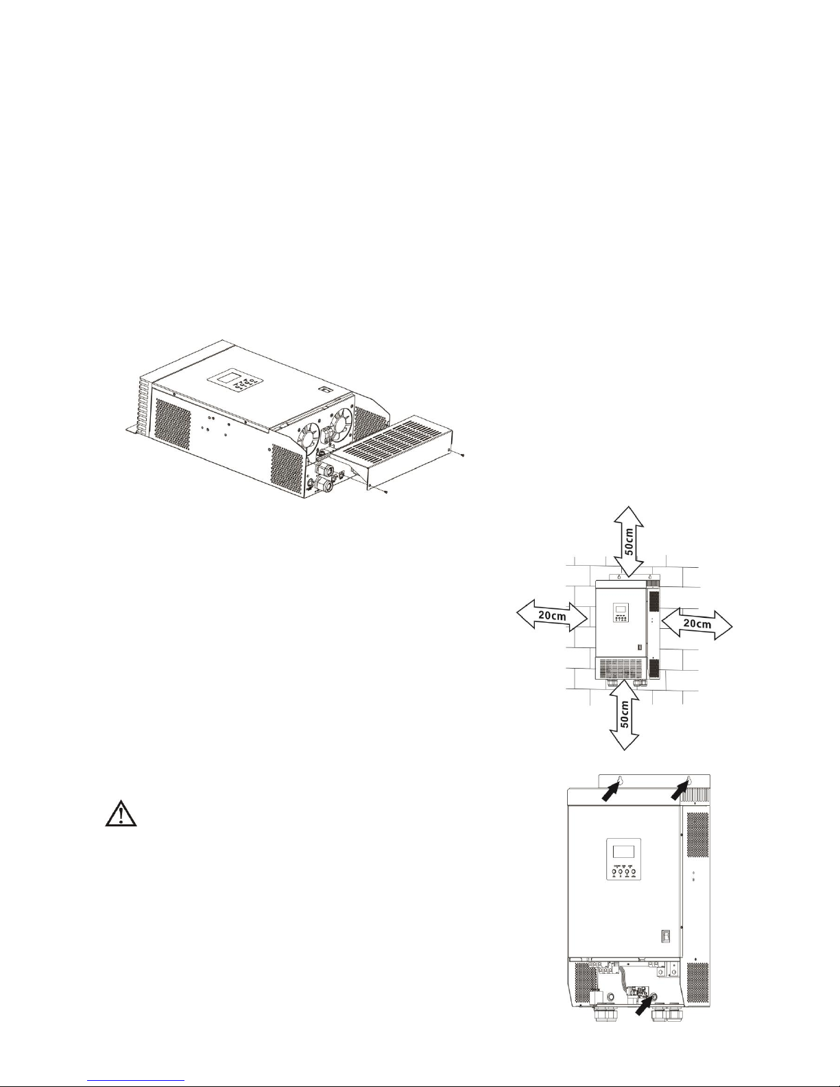
Mounting the Inverter/charger
Consider the following points before selecting where to install:
Do not mount the inverter/charger on any flammable
construction materials.
Mount this inverter/charger on a solid surface, like board
(thickness ≥ 15mm), metal frame, or cement wall.
Install this inverter/charger at eye level in order to read the LCD
display at all times.
The ambient temperature should be between 0°C and 55°C to
ensure optimal operation.
The inverter/charger should be adhered to the wall vertically.
Be sure to keep other objects away and leave the space in a
minimum as shown in the right diagram to guarantee
sufficient heat dissipation and enough space for replacing
wires.
SUITABLE FOR MOUNTING ON CONCRETE OR OTHER
NON-COMBUSTIBLE SURFACE ONLY.
Install the inverter/charger by screwing three screws as shown in the diagram.
It’s recommended to use M4 or M5 screws.

5
Grounding
CAUTION: For safety, it’s requested to connect the device to the ground first. Proper grounding can not only
remove the unwanted “electrical noise” but can even make surge protection device work better. Please refer to
the typical requirement in the table below as required grounding cables.
Suggested cable requirement for grounding
Gauge
Torque Value
Color
8 AWG
2.52 Nm
Green
Please refer to the diagram below to complete the grounding:
Battery Connection
CAUTION: For safety operation and regulation compliance, it’s requested to install a separate DC over-current
protector or disconnect the device between battery and inverter/charger. It may not be necessary to
disconnect the device for some applications, however, it’s requested to have over-current protection installed.
Please refer to the typical amperage in the table below as required fuse or size of the breaker.
CAUTION: To reduce the risk of fire, connect only to a Battery circuit provided with 50 amperes maximum
branch-circuit overcurrent protection in accordance with the NEC, ANSI/NFPA 70.
WARNING! All wiring must be performed by a qualified personnel.
WARNING! It's very important for system safety and efficient operation to use
appropriate cable for battery connection. To reduce risk of injury, please use
proper cables and suitable size of terminal recommended below.
Recommended battery cables and size of terminal:
Model
Typical
Amperage
Battery
Capacity
Wire Size
Ring Terminal
Torque Value
Cable
mm2
Dimensions
D (mm)
L (mm)
2KVA 48V
33A
100AH
1*10AWG
5
6.4
22.5
2.07~ 2.3 Nm
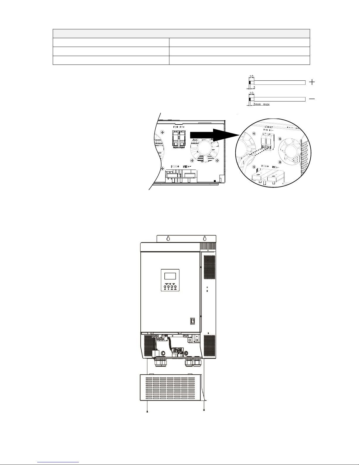
Please follow the steps below to implement the battery connection:
1. Assemble battery ring terminal according to the recommended battery cable and terminal size.
2. Connect all battery packs according to the requirement of the inverter/charger. It’s suggested to connect at
least 100Ah capacity battery.
3. Insert the ring terminal of battery cable flatly into battery connector of inverter/charger and make sure the
bolts are tightened with torque of 2-3 Nm. Make sure polarities at both the battery and the
inverter/charger is correctly connected and ring terminals are tightly screwed to the battery terminals.
Ring terminal:

6
WARNING: Shock Hazard
Installation must be performed with care due to high battery voltage in series.
CAUTION!! Do not place anything between the flat part of the inverter/charger terminal and the
ring terminal. Otherwise, overheating may occur.
CAUTION!! Do not apply any anti-oxidant substance on the terminals before the terminals are
connected tightly.
CAUTION!! Before making the final DC connection or closing DC breaker/disconnector, be sure
positive (+) must be connected to positive (+) and negative (-) must be connected to negative (-).
AC Input/Output Connection
CAUTION!! To reduce the risk of fire, connect only to an AC line circuit provided with 30 amperes maximum
branch-circuit overcurrent protection in accordance with the National Electric Code, ANSI/NFPA 70 by the
installer.
CAUTION!! There are two terminal blocks with “IN” and “OUT” markings. Please do NOT mis-connect input
and output connectors.
WARNING! All wiring must be performed by the qualified personnel.
WARNING! It's very important for system safety and efficient operation to use appropriate cable for AC input
connection. To reduce risk of injury, please use the recommended cable size as below.
Suggested cable requirement for AC wires
Gauge
Torque Value
12 AWG
2.07~ 2.3 Nm
Please follow below steps to implement AC input/output connection:
1. Before making AC input/output connection, be sure to open DC protector or disconnector first.
2. Remove insulation sleeve 10mm from the six conductors. And short-circuit phase L and neutral conductor N
3 mm.
3. Insert AC input wires according to polarities indicated on terminal block and tighten the terminal screws. Be
sure to connect PE protective conductor ( ) first.
→Ground (yellow-green)
L→LINE (brown or black)
N→Neutral (blue)

7
WARNING:
Be sure that AC power source is disconnected before attempting to hardwire it to the
inverter/charger.
4. Then, insert AC output wires according to polarities indicated on terminal block and fasten the terminal
screws. Be sure to connect PE protective conductor ( ) first.
→Ground (yellow-green)
L→LINE (brown or black)
N→Neutral (blue)
5. Make sure the wires are securely connected.
PV Connection
CAUTION: Before connecting to PV modules, please install separately a DC circuit breaker between the
inverter/charger and PV modules.
WARNING! All wiring must be performed by a qualified personnel.
WARNING! It's very important for system safety and efficient operation to use appropriate cable for PV
module connection.
To reduce risk of injury, please use the recommended cable size as below.
Typical Amperage
Cable Size
Torque
45 A
6 AWG
3.6 Nm
PV Module Selection:
When selecting proper PV modules, please be sure to consider the parameters below:
1. Open circuit Voltage (Voc) of PV modules can’t exceed the maximum voltage of the PV array open circuit of
the inverter/charger.
CAUTION: Important
Be sure to connect AC wires with correct polarity. If L and N wires are connected reversely, it may cause utility
short-circuited.
CAUTION: Appliances such as air conditioner are required at least 2~3 minutes to restart because it’s required
to have enough time to balance refrigerant gas inside of circuits. If a power shortage occurs and recovers in a
short time, it will cause damage to your connected appliances. To prevent this kind of damage, please check with
the manufacturer of the air conditioner if it’s equipped with time-delay function before installation. Otherwise,
this inverter/charger will cause overload fault and cut off the output to protect your appliance but sometimes it
still causes internal damage to the air conditioner.
CAUTION: Important
Be sure that the AC output / neutral is not bonded to ground inside of the inverter.
8
2. Open circuit Voltage (Voc) of PV modules should be higher than the minimum voltage of the battery.
Please follow the steps below to implement PV module connection:
1. Remove insulation sleeve 10 mm from positive and negative conductors.
2. Check the correct polarity of connected cable from PV modules and PV input
connectors. Then, connect positive pole (+) of connection cable to positive
pole (+) of PV input connector. Connect negative pole (-) of connection
cable to negative pole (-) of PV input connector.
3. Make sure the wires are securely connected.
Final Assembly
After connecting all wirings, please put the bottom cover back by fixing two screws as shown below.
Solar Charging Mode
Max. PV Array Open Circuit Voltage
145Vdc
PV Array MPPT Voltage Range
60~115Vdc
Min. battery voltage for PV charge
34Vdc

9
Communication Connection
Please use supplied RS232 cable to connect to the inverter/charger and PC. Insert bundled CD into a computer
and follow the on-screen instructions to install the monitoring software. For the detailed software operations,
please check user manual of software inside the CD.
There is one RS485 port reserved for communication with external battery management system.

10
OPERATION
Power ON/OFF
Once the inverter/charger has been properly installed and the batteries are connected well, simply press
On/Off switch (located on the right corner of the top panel) to turn on the inverter/charger.
Operation and Display Panel
The operation and display panel, as shown in the chart below, are on the front panel of the inverter/charger.
It includes three indicators, four function keys and an LCD display, indicating the operating status and
input/output power information.
LED Indicator
LED Indicator
Messages
Green
Solid On
Output is powered by utility in Line mode.
Flashing
Output is powered by battery or PV in battery mode.
Green
Solid On
Battery is fully charged.
Flashing
Battery is charging.
Red
Solid On
Fault occurs in the inverter/charger.
Flashing
Warning occurs in the inverter/charger.
LCD display
LED indicators
Function keys
11
Function Keys
Function Key
Description
ESC
To exit setting mode
UP
To go to previous selection
DOWN
To go to next selection
ENTER
To confirm the selection in setting mode or enter setting mode
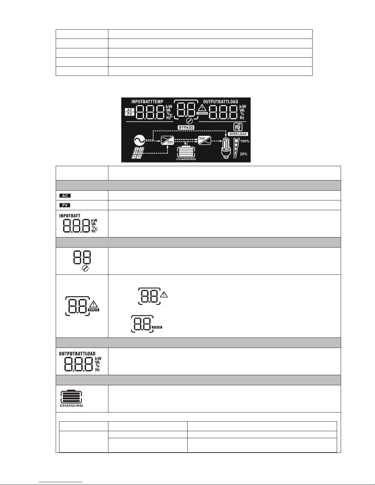
LCD Display Icons
Icon
Function description
Input Source Information
Indicates the AC input.
Indicates the PV input
Indicates input voltage, input frequency, PV voltage, battery voltage and charger current.
Configuration Program and Fault Information
Indicates the setting programs.
Indicates the warning and fault codes.
Warning: flashing with warning code.
Fault: lighting with fault code
Output Information
Indicate output voltage, output frequency, load percent, load in VA, load in Watt and
discharging current.
Battery Information
Indicates battery level by 0-24%, 25-49%, 50-74% and 75-100% in battery mode and
charging status in line mode.
In AC mode, it will present battery charging status.
Status
Battery voltage
LCD Display
Constant
Current mode /
Battery level < 25%
4 bars will flash in turns.
25% ≤battery level < 50%
Bottom bar will be on and the other three bars will flash
in turns.
12
Constant Voltage
mode
50% ≤ battery level < 75%
Bottom two bars will be on and the other two bars will
flash in turns.
Battery level ≥ 75%
Bottom three bars will be on and the top bar will flash.
In floating mode, batteries are fully charged.
4 bars will be on.
In battery mode, it will present battery capacity.
Battery Voltage
LCD Display
battery level < 25%
25%≤ battery level < 50%
50%≤ ba tery level < 75%
battery level ≥ 75%
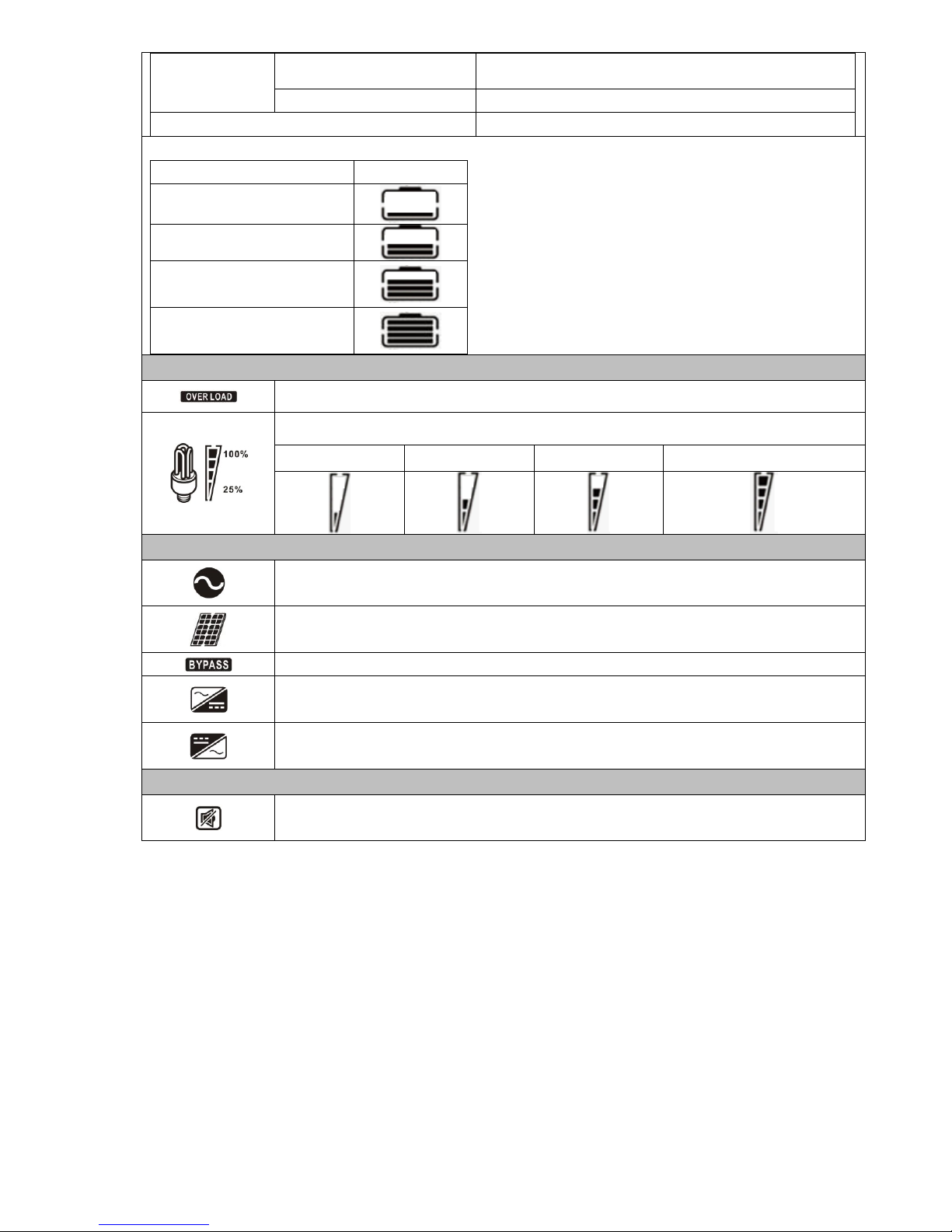
Load Information
Indicates overload.
Indicates the load level by 0-24%, 25-49%, 50-74% and 75-100%.
0%~24%
25%~49%
50%~74%
75%~100%
Mode Operation Information
Indicates inverter/charger connects to the mains.
Indicates inverter/charger connects to the PV panel.
Indicates load is supplied by utility power.
Indicates the utility charger circuit is working.
Indicates the DC/AC inverter circuit is working.
Mute Operation
Indicates the alarm is disabled.

13
LCD Setting
After pressing and holding the ENTER button for 3 seconds, the inverter/charger will enter setting mode. Press
“UP” or “DOWN” button to select setting programs. And then, press “ENTER”button to confirm the selection or
ESC button to exit.
Setting Programs:
Program
Description
Selectable option
00
Exit setting mode
Escape
01
Output source priority:
To configure load power
source priority
Solar first
Solar energy provides power to the
loads as first priority.
If solar energy is not sufficient to
power all connected loads, battery
energy will supply power the loads at
the same time.
Utility provides power to the loads
only when any one condition
happens:
- Solar energy is not available
- Battery voltage drops to low-level
warning voltage.
Utility first (default)
Utility will provide power to the loads
as first priority.
Solar and battery energy will provide
power to the loads only when utility
power is not available.
SBU priority
Solar energy provides power to the
loads as first priority.
If solar energy is not sufficient to
power all connected loads, battery
energy will supply power to the loads
at the same time.
Utility provides power to the loads
only when battery voltage drops to
low-level warning voltage.
02
Maximum charging current:
To configure total charging
current for solar and utility
chargers.
(Max. charging current =
utility charging current +
solar charging current)
10A
20A
30A
40A
50A
60A (default)
03
AC input voltage range
Appliances (default)
If selected, acceptable AC input
voltage range will be within 65-140
VAC.

14
UPS
If selected, acceptable AC input
voltage range will be within
95-140VAC.
04
Power saving mode
enable/disable
Saving mode disable
(default)
If disabled, no matter connected load
is low or high, the on/off status of
inverter output will not be effected.
Saving mode enable
If enabled, the output of inverter will
be off when connected load is pretty
low or not detected.
05
Battery type
AGM (default)
Flooded
User-Defined
If “User-Defined” is selected, battery
charge voltage and low DC cut-off
voltage can be set up in program 26,
27 and 29.
07
Auto restart when over
temperature occurs
Restart disable
(default)
Restart enable
08
Output voltage
110V
120V (default)
09
Output frequency
50Hz
60Hz (default)
11
Maximum utility charging
current
5A
10A(default)
12
Setting voltage point back
to utility source when
selecting “SBU priority” or
“Solar first”in program 01.
44V
45V
46V (default)
47V
48V
49V
50V
51V

15
13
Setting voltage level back to
battery mode when
selecting “SBU priority”or
“Solar first”in program 01.
Battery fully charged
48V
49V
50V
51V
52V
53V
54V (default)
55V
56V
57V
58V
16
Charger source priority:
To configure charger source
priority
If this inverter/charger is working in Line, Standby or Fault
mode, charger source can be programmed as below:
Solar first
Solar energy will charge battery as
first priority.
Utility will charge battery only when
solar energy is not available.
Utility first (Default)
Utility will charge battery as first
priority.
Solar energy will charge battery only
when utility power is not available.
Only Solar
Solar energy will be the only charger
source no matter utility is available or
not.
If this inverter/charger is working in Battery mode or Power
saving mode, only solar energy can charge battery. Solar
energy will charge battery if it's available and sufficient.
18
Alarm control
Alarm on (default)
Alarm off
16
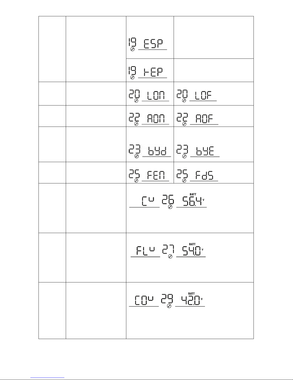
19
Auto return to default
display screen
Return to default
display screen
(default)
If selected, no matter how users
switch display screen, it will
automatically return to default display
screen (Input voltage /output
voltage) after no button is pressed for
1 minute.
Stay at latest screen
If selected, the display screen will
stay at latest screen user finally
switches.
20
Backlight control
Backlight on (default)
Backlight off
22
Beeps while primary source
is interrupted
Alarm on (default)
Alarm off
23
Overload bypass:
When enabled, the
inverter/charger will
transfer to line mode if
overload occurs in battery
mode.
Bypass disable
(default)
Bypass enable
25
Record Fault code
Record enable
Record disable (default)
26
Bulk charging voltage
(C.V voltage)
Default setting: 56.4V
If self-defined is selected in program 5, this program can be
set up. Setting range is from 48.0V to 58.4V. Increment of
each click is 0.1V.
27
Floating charging voltage
Default setting: 54.0V
If self-defined is selected in program 5, this program can be
set up. Setting range is from 48.0V to 58.4V. Increment of
each click is 0.1V.
29
Low DC cut-off voltage
Default setting: 42.0V
If self-defined is selected in program 5, this program can be
set up. Setting range is from 40.0V to 48.0V. Increment of
each click is 0.1V. Low DC cut-off voltage will be fixed to
setting value no matter what percentage of load is connected.

17
Display Setting
The LCD display information will be switched in turns by pressing “UP” or “DOWN” key. The selectable
information is switched as below order: input voltage, input frequency, PV voltage, MPPT charging current,
MPPT charging power, battery voltage, output voltage, output frequency, load percentage, load in VA, load in
Watt, DC discharging current, main CPU Version and second CPU Version.
Selectable information
LCD display
Input voltage/Output voltage
(Default Display Screen)
Input Voltage=120V, output voltage=120V
Input frequency
Input frequency=60Hz
PV voltage
PV voltage=60V
MPPT Charging current
Current ≧10A
Current < 10A
MPPT Charging power
MPPT charging power=500W

18
Battery voltage/ DC discharging current
Battery voltage=50.5V, discharging current=1A
Output frequency
Output frequency=60Hz
Load percentage
Load percent=70%
Load in VA
When connected load is lower than 1kVA, load in
VA will present xxxVA like below chart.
When load is larger than 1kVA (≧1KVA), load in
VA will present x.xkVA like below chart.
Table of contents
Other MPP Solar Batteries Charger manuals


