5
P: 479.419.4800 | F: 479.419.4801 | www.purkeys.net
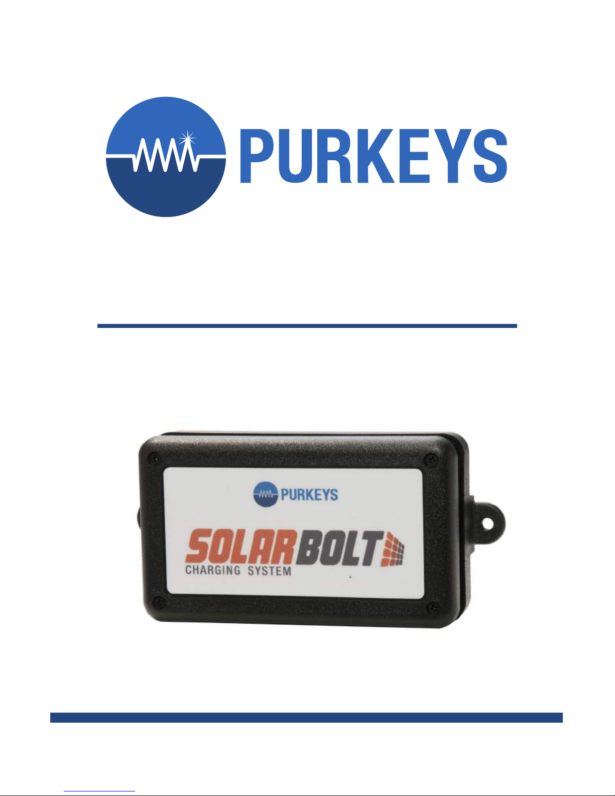
SOLAR BOLT INSTALLATION GUIDE
SOLAR PANEL INSTALL PROCESS
Note: If completing an install in temperatures lower than room
temperature, keep the panel and EternaBond RoofSeal at room
temperature until just before the installation.
Step 1: Partially remove the backing material from the mastic of the panel and
place panel according to the alignment marks.
Step 2: Pull the backing o the mastic as the panel is laid down on the surface.
e panel should be laid down by rolling the panel onto the bond surface;
this will ensure there are no air bubbles under the panel.
Step 3: Apply pressure by rubbing the panel by hand, making sure the mastic
meets the bond surface. Some trailer and box truck surfaces are not very
at, and you will need to take caution to make sure the panel is bonded
down as the panel is rolled out.
Step 4: Aer the panel mastic is bonded to the surface suciently, prepare for
the edge seal by lightly abrading the edge 1” of the solar panel and 1” of the
adjacent metal surface with Scotch-Brite.
Step 5: Clean the edge by adding isopropyl alcohol to the cleaning rag, wiping
the edge bonding surface. Make sure all loose material and residue from
sanding prep is removed. Be careful not to oversaturate the edge of the
solar panel where the mastic is exposed. Allow the isopropyl alcohol to
completely dry (10-15 minutes) before applying the edge seal.
Step 6: Apply the edge seal by applying the Eternabond RoofSeal 2” tape.
Apply by overlapping the panel (1” and bond surface 1”) and bond surface
to seal the edge. e tape seal should be applied from back to front of the
trailer to allow overlapping edges to be covered and not be exposed to the
wind as much as possible. e front edge will be applied last and two layers
should be applied to assure the wind will not pry up the edges of the front
of the panel. Apply with good pressure from hands or a rubbing tool per
EternaBond Installation Instructions.
Note: for extra edge seal and bonding the 4” wide Eternabond RoofSeal
may be used.