GE WattStation Wall Mount User manual

GE Energy
WattStation™ Wall Mount
User Manual

WattStation™ Wall Mount User Manual
2GE Energy ©2012 GE Company All Rights Reserved
!
!
Table of Contents
1. Grounding Instructions..............................................................................................................................................................3
1.1 Safety and Compliance......................................................................................................................................................3
1.2 Grounding Instructions......................................................................................................................................................3
2. Installation Instructions.............................................................................................................................................................3
2.1 Installation Tools and Requirements...........................................................................................................................3
2.2 Plug-in Version......................................................................................................................................................................3
2.2.1 Before Installation ......................................................................................................................................................3
2.2.2 Installation.......................................................................................................................................................................4
2.3 Hardwired Version........................................................................................................................................................7
2.3.1 Before Installation .......................................................................................................................................................7
2.3.2 Installation.......................................................................................................................................................................7
3.1 Basic Features.......................................................................................................................................................................9
3.2 Turning WattStation On and Off...................................................................................................................................9
3.3 Connecting and Disconnecting to Vehicle...............................................................................................................9
3.4 Technical Information ....................................................................................................................................................10
3.5 Fault Indication...................................................................................................................................................................11
3.6 Fuse Replacement.............................................................................................................................................................11
4. LIMITED WARRANTY FOR GE WattStationTM (Wall) (“this Warranty”) .............................................................11
WattStation should be installed only a licensed contractor, and/or a licensed electrician in
accordance with all applicable state, local and national electrical codes and standards. WattStation
should be inspected by a qualified inspector prior to initial use. Under no circumstances will
compliance with the information in this manual relieve the user of his/her responsibility to comply
with all applicable codes or safety standards.

WattStation™ Wall Mount User Manual
3GE Energy ©2012 GE Company All Rights Reserved
!
1. Grounding Instructions
1.1 Safety and Compliance
Read all instructions before using this product.
Do not use this product if the flexible power cord or charging cable are frayed, have broken insulation, or
any other signs of damage.
Do not use this product if the enclosure or the charging connector is broken, cracked, open, or show any
other indication of damage.
This document provides instructions for the wall mounted WattStation and should not be used for any
other product. Before installing WattStation you should review this manual carefully and consult with a
licensed contractor, licensed electrician, or trained installation expert to ensure compliance with local
building codes, climate conditions, safety standards and state and local electrical codes.
1.2 Grounding Instructions
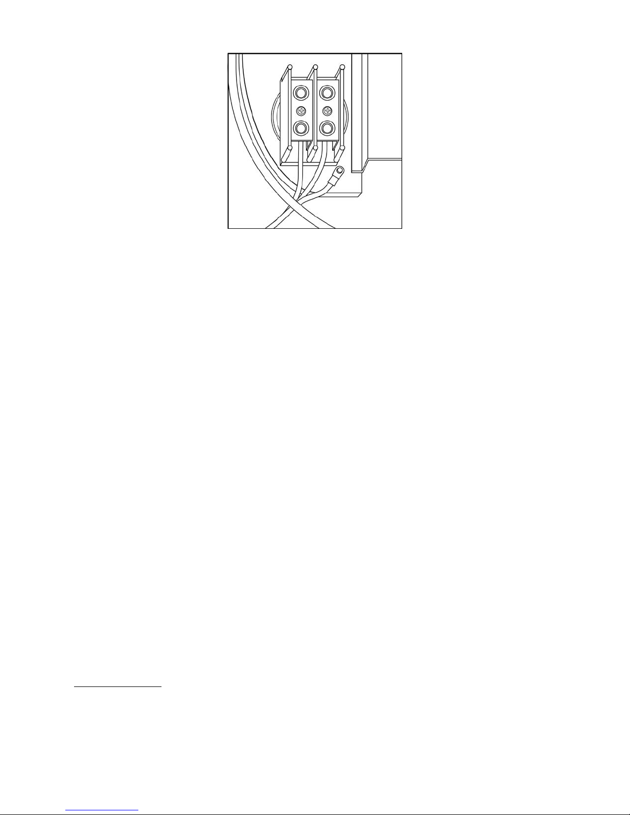
WattStation must be connected to a centrally grounded electrical system. Ground conductors entering
WattStation must be connected to the equipment grounding bar inside the charger. Connections to
WattStation shall comply with all applicable electrical codes and ordinances.
2. Installation Instructions
2.1 Installation Tools and Requirements
Recommended Tools:
•Slotted screwdriver (3/16” or ¼”)
•Electric drill
•Wire stripper
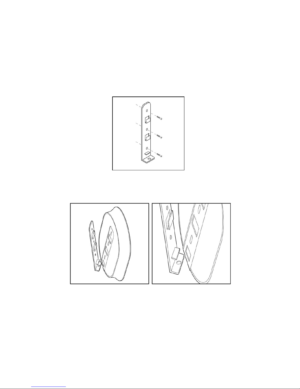
•Wall mounting hardware (refer to section 2.2.1 or section 2.3.1)
•Phillip’s head screwdriver
•Water-tight conduit hub (hardwired version only)
2.2 Plug-in Version
2.2.1 Before Installation
WattStation should be installed only by a licensed contractor, and/or a licensed electrician in
accordance with all applicable state, local and national electrical codes and standards.
•Ensure that a dedicated circuit, capable of supplying 30A at 208-240 VAC, is available
•Power feed must have a centrally grounded neutral in order for WattStation to function correctly.
•Wall receptacle must be a NEMA 6-50 outlet. A recommended 40A upstream circuit breaker,
located either in a panelboard or load center, should be used
•Distance between the wall power receptacle and WattStation mounting should be less than one
(1) foot
•Wall power receptacle with a weatherproof locking cover is required

WattStation™ Wall Mount User Manual
4GE Energy ©2012 GE Company All Rights Reserved
!
•Recommended mounting hardware for wood studs are 1/4" x 2" hex head lag bolts.
Recommended mounting hardware for concrete walls are 1/4" x 1-3/4" concrete hex screws or
1/4" x 1-7/8" concrete anchors
WARNING: Danger of electrical shock or injury. Turn OFF power at the panelboard or load center before
working inside the equipment or removing any component. Do not remove circuit protective devices or
any other component until the power is turned OFF.
2.2.2 Installation
Step 1: Carefully unwrap the packaging and make sure the following items are present:
-Wall Mounted WattStation unit
-Mounting wall bracket
-Key for WattStation mounting lock
WattStation Wall Mount User Manual
Torque Specification Table:
COMPONENT
TORQUE VALUE
TOLERANCE
M5 x 0.8 screw
30 in-lb
+/-2 in-lb
#12 thread-cutting screw
30 in-lb
+/-2 in-lb
10-32 UNF screw
35 in-lb
+/-5 in-lb
6-32 UNC screw
12 in-lb
+/-2 in-lb
Fuse block lugs
45 in-lb
+/-2 in-lb
Field wiring lugs
50 in-lb
+/-2 in-lb
Din-rail mounted terminal block
lugs
12 in-lb
+/-2 in-lb
Contactor lugs
50 in-lb
+/-2 in-lb
Ground bar lugs
35 in-lb
+/-2 in-lb
M3 x 0.5 screw
12 in-lb
+/-2 in-lb
#8 thread cutting screw
30 in-ib
+/-2 in-lb
3/4" cable strain relief fitting
Hand-Tight + 1/4 turn
N/A

WattStation™ Wall Mount User Manual
5GE Energy ©2012 GE Company All Rights Reserved
!
Step 2: Check for any damage to the unit, the cord or the connector. If no damage is noticed, proceed to
step 3. If damage is noticed, call 1-888-GE-RESOLve.
Step 3: Install wall mount bracket to the wall. Use the mounting wall bracket as a template for the wall-
mounting holes. The distance from the floor to bottom of the wall mount bracket should be 18” minimum
for indoor use and 24” minimum for outdoor use. The distance to the top of the unit should be 48”
maximum for all applications per NEC 625.29. For ADA compliant installation, refer to ADA accessibility
guidelines, section 4.2
Step 4: Slide WattStation unit onto the mounting bracket, ensuring that the opening in the back plate
bracket aligns with the tab on the wall mount bracket by first carefully disconnecting the wires
connecting the front cover.

WattStation™ Wall Mount User Manual
6GE Energy ©2012 GE Company All Rights Reserved
!
Step 5: Unwrap the plug-in cord and plug into the wall receptacle
Step 6:Lock weatherproof receptacle cover (not supplied with WattStation)
Step 5: Lock the WattStation unit onto the mounting bracket using
the provided key

WattStation™ Wall Mount User Manual
7GE Energy ©2012 GE Company All Rights Reserved
!
2.3 Hardwired Version
2.3.1 Before Installation
WattStation should be installed only by a licensed contractor, and/or a licensed electrician in
accordance with all applicable state, local and national electrical codes and standards.
WARNING: Danger of electrical shock or injury. Turn OFF power at the panelboard or load center before
working inside the equipment or removing any component. Do not remove circuit protective devices or
any other component until the power is turned OFF.
•Ensure that a dedicated circuit, capable of supplying 30A at 208-240 VAC, is available
•Power feed must have a centrally grounded neutral in order for WattStation to function correctly.
•A recommended 40A upstream circuit breaker, located either in a panelboard or load center,
should be used
•Power and ground wires for WattStation go in through the back of the unit as a default.
Optionally, the power may be fed through the bottom or top of the unit. Plan ahead on how you
will supply power to WattStation
•Recommended mounting hardware for wood studs are 1/4" x 2" hex head lag bolts
•Recommended mounting hardware for concrete walls are 1/4" x 1-3/4" concrete hex screws or
1/4" x 1-7/8" concrete anchors
2.3.2 Installation
Step 1: Carefully unwrap the packaging and make sure the following items are present:
Step 2: Check for any damage to the unit, the cord or the connector. If no damage is noticed, proceed to
step 3. If damage is noticed, call 1-888-GE-RESOLve.
-Wall Mounted WattStation unit
-Mounting wall bracket
-Key for WattStation mounting lock
Step 3: Install wall mount bracket to the wall. Use the mounting wall bracket as a template for the wall-
mounting holes. The distance from the floor to bottom of the wall mount bracket should be 18” minimum
for indoor use and 24” minimum for outdoor use. The distance to the top of the unit should be 48”
maximum for all applications per NEC 625.29. For ADA compliant installation, refer to ADA accessibility
guidelines, section 4.2. Make sure the bracket is aligned so that power wire will fit through the WattStation
enclosure holes (for back-entry wiring only).

WattStation™ Wall Mount User Manual
8GE Energy ©2012 GE Company All Rights Reserved
!
Step 4: Remove the oval snap-fit ring to access the cover hardware. Take off front cover and the
deadfront shield by first carefully disconnecting the wires connecting the front cover.
Disconnect from Vehicle: WattStation can be disconnected from the vehicle at any time.
Press and hold the button on top of the connector handle and pull the handle away from the vehicle inlet
socket. The charge status indicator light will turn off.
Replace the connector handle into the WattStation holder by pushing the connector into the inlet. This will
ensure the connector is locked with the metal inlet of the WattStation holder.
Step 5: Remove the wire pigtail from the line side of field wiring block and discard.

WattStation™ Wall Mount User Manual
9GE Energy ©2012 GE Company All Rights Reserved
!
Step 6: Feed the supply power and ground wires through WattStation enclosure holes. Slide WattStation
onto the mounting bracket, ensuring that the opening in the back plate bracket aligns with the tab on the
wall mount bracket.
Step 7: Connect supply power wires to line side of fuse block and ground wire to the ground bar.
Step 8: Replace the deadfront shield and reconnect the wires going to the front cover components and
replace the oval snap-fit ring.
3. User Manual
3.1 Basic Features
•Charging cord and connector provide link to electric vehicle
•LED ring provides illumination around connector
•Green indicator light displays when WattStation is in charge mode
•Red indicator light displays when WattStation is in fault mode
•On/Off button allows total power shutdown
•Tamper-proof / theft-proof key lock secures WattStation to the wall bracket
•Padlock option on connector provides additional physical security
•Availability of plug-in or hardwired version provides installation flexibility
•Entry options for supply power cable include top, bottom and rear and provide additional
flexibility for the hardwired version
3.2 Turning WattStation On and Off
WattStation can be turned on by pressing in the On/Off pushbutton. When on, the LED ring around the
connector will glow white.
WattStation can be turned off at any time by pressing the On/Off button again. The LED ring will turn off.
3.3 Connecting and Disconnecting to Vehicle
Connect to Vehicle When the connector is seated in the WattStation holder, press and hold the button on
the connector handle and pull away from the holder until it is fully removed.
Press and hold the button on the connector handle and insert into the vehicle’s inlet socket. Release the
button on the connector handle when fully connected to the vehicle inlet socket.
Once the WattStation handle is connected to the vehicle, the charge status indicator will illuminate green.

WattStation™ Wall Mount User Manual
10 GE Energy ©2012 GE Company All Rights Reserved
!
SAE Compliant
Level II per J1772
Vehicle Interface
SAE J1772 EV connector
Cable Length
16’ cable
AC Max Charging Power Output**
7.2 kW (240VAC @ 30A)
Voltage and Current Rating
208
-240VAC @ 30A
AC Power Input
208
-
240VAC requiring only Line 1, Line 2 and
Earth ground
Recommended Service Panel
2-
pole 40A breaker on dedicated circuit
Breaker
Ground Fault Protection
Internal 20mA CCID with auto-re-closure, does
not require a GFCI in service panel
Ground Monitoring
Ensures ground is present between vehicle
and WattStation, and between WattStation and
load center
Standby Power
0 W when not charging and turned off by
pushbutton switch
Outdoor Rated
NEMA 3R
Safety Compliance
ETL and CETL listed conforming to UL 2594,
2231 and 1998
Surge Protection
6kV @ 3000A
EMI Compliance
FCC Part 15 Class A
Operating Temperature
-
30°C to +50°C ambient
Operating Humidity
Up to 95% non-condensing
Unit Weight
35 lbs
Dimensions
24” H x 16” W x 6” D

WattStation™ Wall Mount User Manual
11 GE Energy ©2012 GE Company All Rights Reserved
!
3.4 Technical Information
**WattStation determines the maximum power consumption. EV determines the actual power
consumption.
3.5 Fault Indication
When the fault indicator illuminates red, WattStation is indicating a fault.
Ground Fault: WattStation can detect the presence of ground faults with a threshold of 15–20 mA during
the charging cycle. Once a ground fault is detected, WattStation will stop charging the vehicle and the
fault status indicator will turn red. The WattStation will automatically reset after 15 minutes or if the EV
connector is disconnected from the vehicle.
If four (4) such attempts to restart charging have occurred, WattStation will lockout the station. The
lockout will prevent any vehicle from being charged until the EV connector has been disconnected from
the vehicle. The fault indicator will illuminate as solid red. It is highly recommended that service
personnel examine the EV (electric vehicle) and/or the charging cable to determine the cause of the
multiple faults before re-energizing.
If a ground fault is present immediately after WattStation begins charging, the unit will stop charging and
immediately lockout the station. The lockout will prevent any vehicle from being charged until the EV
connector has been disconnected from the vehicle. The fault indicator will illuminate as solid red.
Fan Fault: WattStation is not suitable for vehicles that require ventilation. It will provide fault indication if a
vehicle requests fan ventilation, as per SAE J1772. The fault indicator will illuminate and turn solid red. The
fault will reset if the user removes the WattStation connector from the vehicle.
Overvoltage/Undervoltage Faults: WattStation monitors line voltage and cuts power to the EV if the
voltage goes out of range. After one (1) minute, it rechecks the voltage and will automatically re-enable
charging if the voltage returns to an acceptable range. The fault indicator will illuminate as blinking red.
3.6 Fuse Replacement
In the event that a fuse needs to be replaced, de-energize the upstream breaker feeding this equipment
before opening the cover. Remove the front cover as described in Step 4 of Section 2.32. The fuses will
then be accessible through the dead front shield. Remove old fuses by using a fuse puller tool.
Replacement fuses should be Cooper-Bussmann NON-40, Class K5.
4. LIMITED WARRANTY FOR GE WattStationTM (Wall)
WARRANTY
Any one or more of the following actions acknowledges that you have read and agree to the terms of this
warranty agreement: Your use of the GE WattStation (Wall) packaged with this Instruction Manual (the
“Hardware”), online product registration of the Hardware, or your return of the enclosed Registration Card.
GE’s warranty obligations for this Hardware product are limited to the terms set forth in this Limited
Warranty and are limited by and subject to the Exclusions and Limitations set out below.

WattStation™ Wall Mount User Manual
12 GE Energy ©2012 GE Company All Rights Reserved
!
GE warrants that this Hardware product shall be free of defects in materials and workmanship under
normal use for a period of three (3) years from the date of manufacture (the “Warranty Period”). If a
defect in the Hardware arises and a valid claim is received within the Warranty Period, your sole and
exclusive remedy will be for GE, in its sole discretion and to the extent permitted by law, to (1) repair the
defect in the Hardware at no charge, using new parts or refurbished parts, or (2) exchange the Hardware
with new or refurbished hardware that is functionally equivalent to the original Hardware, (the repaired
Hardware and the exchanged hardware are called the “Remedied Hardware”). Any Remedied Hardware
product will be warranted for the remainder of the original warranty period or ninety (90) days from
delivery to the customer, whichever is longer. In order to receive the remedy set forth above, you must
contact GE during the Warranty Period at 888-437-3765 and provide the model number, serial number
and date of purchase. Upon GE’s determination that the Hardware product should be returned to GE,
return the Hardware and include with each returned item of Hardware (i) a copy of your original purchase
invoice or receipt to verify your warranty; (ii) your name, address, and telephone number; (iii) the Return
Materials Authorization (RMA) number.
In addition to the foregoing Hardware product warranty, during the Warranty Period, GE shall also provide
telephone (888-437-3765) technical support assistance.
Please note that the above warranty obligations of GE do not apply to installation service of the
Hardware.
EXCLUSIONS AND LIMITATIONS
This warranty applies only to the Hardware manufactured by or for GE that can be identified by the “GE”
trademark, trade name, or logo affixed to it. This warranty does not apply to any non-GE hardware
product or any software, even if packaged or sold with the Hardware. Software distributed by GE with or
without the GE brand name (including, but not limited to system software) is not covered under this
warranty. Refer to the End User Licensing Agreement accompanying the software for details of your rights
with respect to its use.
GE does not warrant that the operation of the Hardware will be uninterrupted or error-free. GE is not
responsible for damage arising from failure to follow instructions relating to the Hardware’s use.
This warranty does not apply to: (a) consumable parts, such as batteries, or protective coatings designed
to diminish over time unless failure has occurred due to a defect in materials or workmanship; (b)
cosmetic damage; (c) damage caused by use with non-GE products; (d) damage caused by accident,
abuse, misuse, liquid contact, fire, earthquake or other external causes; (e) damage caused by operating
the Hardware product outside the permitted or intended uses described by GE; (f) damage caused by
service (including upgrades and expansions) not performed by GE, a GE-authorized service provider, an
authorized representative of GE, or a qualified electrician; (g) a product or part that has been modified to
alter functionality or capability without the written permission of GE; (h) defects caused by normal wear
and tear or otherwise due to the normal aging of the product; (i) removed or defaced GE serial numbers;
or (j) damage caused by or via the network on which the Hardware product is used including, but not
limited to, any online intrusion or attack.
Important: Do not open, take apart or disassemble the Hardware in any way. Doing so may cause
damage that is not covered by this warranty. Only GE or a GE authorized service provider should perform
service on the Hardware.

WattStation™ Wall Mount User Manual
13 GE Energy ©2012 GE Company All Rights Reserved
!
TO THE EXTENT PERMITTED BY LAW, THIS WARRANTY AND THE REMEDIES SET FORTH ABOVE ARE
EXCLUSIVE AND IN LIEU OF ALL OTHER WARRANTIES, REMEDIES AND CONDITIONS, WHETHER ORAL,
WRITTEN, STATUTORY, EXPRESS OR IMPLIED. TO THE EXTENT PERMITTED BY APPLICABLE LAW, GE
SPECIFICALLY DISCLAIMS ANY AND ALL STATUTORY OR IMPLIED WARRANTIES, INCLUDING, WITHOUT
LIMITATION, WARRANTIES OF MERCHANTABILITY AND FITNESS FOR A PARTICULAR PURPOSE AND
WARRANTIES AGAINST HIDDEN OR LATENT DEFECTS. IF GE CANNOT LAWFULLY DISCLAIM STATUTORY OR
IMPLIED WARRANTIES THEN TO THE EXTENT PERMITTED BY LAW, ALL SUCH WARRANTIES SHALL BE
LIMITED IN DURATION TO THE DURATION OF THE EXPRESS WARRANTY PROVIDED IN THS WARRANTY
SECTION AND TO THE REPAIR OR REPLACEMENT SERVICE PROVIDED IN THIS WARRANTY SECTION AND
EXCLUSIONS AND LIMITATIONS PROVISION SUB-SECTION, IN EACH CASE AS DETERMINED BY GE. No oral or
written information or advice given by GE or a GE-authorized representative shall modify or extend any
warranty. If any provision is held to be illegal or unenforceable, the legality or enforceability of the
remaining provisions shall not be affected or impaired.
EXCEPT AS PROVIDED IN THIS WARRANTY AND TO THE MAXIMUM EXTENT PERMITTED BY LAW, GE IS NOT
RESPONSIBLE FOR DIRECT, SPECIAL, INCIDENTAL OR CONSEQUENTIAL DAMAGES RESULTING FROM ANY
BREACH OF WARRANTY OR CONDITION, OR UNDER ANY OTHER LEGAL THEORY, INCLUDING BUT NOT
LIMITED TO LOSS OF USE; LOSS OF REVENUE OR ACTUAL OR ANTICIPATED PROFITS OR SAVINGS; LOSS OF,
DAMAGE TO, COMPROMISE OR CORRUPTION OF DATA; OR ANY INDIRECT OR CONSEQUENTIAL LOSS OR
DAMAGE HOWSOEVER CAUSED INCLUDING THE REPLACEMENT OF EQUIPMENT AND PROPERTY AND ANY
COSTS OF RECOVERING, PROGRAMMING OR REPRODUCING ANY PROGRAM OR DATA STORED IN OR USED
WITH THE GE PRODUCT. THE FOREGOING LIMITATION SHALL NOT APPLY TO DEATH OR PERSONAL INJURY
CLAIMS, OR ANY STATUTORY LIABILITY FOR INTENTIONAL AND GROSS NEGLIGENT ACTS AND/OR
OMISSION.

WattStationTM is a trademark of General Electric Company.
Information provided is subject to change without notice. Please verify all details with GE. All
Values are design or typical values when measured under laboratory conditions and GE makes
no warranty or guarantee, express or implied, that such performance will be obtained under end-
use conditions.
DEA-533 (6/12)
GE Energy
41 Woodford Ave.
Plainville, CT 06062
www.geindustrial.com
© 2012 General Electric Company

!
GE Energy
WattStation™ Wall Mount
Manual de usuario

WattStation™ Wall Mount User Manual
16 GE Energy ©2012 GE Company All Rights Reserved
!
Tabla de Contenidos
1. Instrucciones de Puesta a Tierra........................................................................................................................................17
1.1 Seguridad y Cumplimiento............................................................................................................................................17
1.2 Instrucciones de conexión a tierra............................................................................................................................17
2. Instrucciones de Instalación ................................................................................................................................................17
2.1 Herramientas de Instalación y Requisitos.............................................................................................................17
2.2 Versión Plug-in....................................................................................................................................................................17
2.2.1 Antes de la instalación ...........................................................................................................................................17
2.2.2 Instalación....................................................................................................................................................................19
2.3 Versión Cableada...............................................................................................................................................................20
2.3.1 Antes de la Instalación...........................................................................................................................................20
2.3.2 Instalación....................................................................................................................................................................21
3. Manual de Usuario....................................................................................................................................................................22
3.1 Funciones Básicas............................................................................................................................................................22
3.2 Encendido y Apagado ....................................................................................................................................................23
3.3 Conexión y Desconexión de Vehículos...................................................................................................................23
3.4 Información Técnica .......................................................................................................................................................24
3.6 Remplazo de fusibles.......................................................................................................................................................25
4. GARANTÍA LIMITADA DE GE WattStationTM (Pared) ...................................................................................................26
WattStation debe ser instalado sólo por un contratista con licencia, y / o con un electricista calificado
de acuerdo con todas las leyes, locales, nacionales y las normas de los códigos eléctricos.
WattStation debe ser inspeccionado por un inspector calificado antes de su uso inicial. En ningún
caso el cumplimiento de la información contenida en este manual exime al usuario de su
responsabilidad de cumplir con todos los códigos o normas de seguridad.

WattStation™ Wall Mount User Manual
17GE Energy ©2012 GE Company All Rights Reserved
!
1. Instrucciones de Puesta a Tierra
1.1 Seguridad y Cumplimiento
Lea todas las instrucciones antes de usar este producto.
No utilice este producto si el cable de alimentación flexible o cable de carga están dañados, el
aislamiento este roto, o cualquier otra señal de daño.
No utilice este producto si el gabinete o el conector de carga se hanroto, agrietado, abierto, o
muestrar cualquier indicación de daño.
Este documento proporciona instrucciones para el WattStation de montaje en pared y no debe ser
utilizado para cualquier otro producto. Antes de instalar el WattStation debe revisar cuidadosamente
este manual y consultar con un contratista con licencia, un electricista calificado, o el experto de
instalación capacitado para garantizar el cumplimiento de los códigos de construcción locales, las
condiciones climáticas, las normas de seguridad y códigos eléctricos locales y estatales.
1.2 Instrucciones de conexión a tierra
WattStation debe estar conectado a un sistema de tierra centralizado.Los conductores de tierra que entran al
WattStation deberán estar conectadosa la barra de tierra del equipo en el interior del cargador.Las
conexiones alWattStation deberáncumplir con todos los códigos eléctricos y ordenanzas.
2. Instrucciones de Instalación
2.1 Herramientas de Instalación y Requisitos
Herramientas recomendadas:
•Destornillador de punta plana (3/16 "o ¼")
•Taladro eléctrico
•Pelacables
•herrajes para montaje en muro (consulte la sección 2.2.1 o la sección 2.3.1)
•Destornillador de cabeza de Phillip
•Glándula pasa cables impermeable (versión cableada solamente)
torque specification table is missing here
2.2 Versión Plug-in
2.2.1 Antes de la instalación
El WattStation debe ser instalado por un contratista con licencia, y/o con un electricista calificado de
acuerdo con todas las leyes, locales y nacionales y las normas de los códigos eléctricos.

WattStation™ Wall Mount User Manual
18 GE Energy ©2012 GE Company All Rights Reserved
!
•Asegúrese de que un circuito dedicado, capaz de suministrar 30A a 208-240 VAC, está disponible
•La alimentación de energía debe tener el neutro aterrizado para que el WattStation funcione
correctamente.
•El enchufe de la pared debe ser de tipo NEMA 6-50 de salida. Se recomienda el uso de un interruptor
de 40A aguas arriba, ubicado ya sea en un centro de carga o tablero de alumbrado
•La distancia entre el receptáculo de alimentación de pared y el WattStation debe ser inferior a un (1)
pie
•El Toma de corriente de pared deberá tener cubierta de intemperieLos tornillos recomendados para el
montaje sobre madera son de 3/8” X 2” cabeza hexagonal. Los tornillos recomendados para montaje
en concreto son de 3/8” x 1-7/8”.
ADVERTENCIA: Peligro de choque eléctrico o lesiones. Apague la electricidad en el tablero o
en el centro de carga antes de trabajar dentro del equipo o de quitar cualquier componente. No
retire los dispositivos de protección de circuitos o cualquier otro componente hasta que se haya
desenergizado el equipo.
Especificación deTorque:
COMPONENTE
TORQUE
TOLERANCIA
Tornillo M5 x 0,8
30 in-lb
+ / -2 in-lb
# 12 tornillo autoroscable
30 in-lb
+ / -2 in-lb
Tornillo 10-32 UNF
35 in-lb
+ / -5 in-lb
Tornillo 6-32 UNC
12 in-lb
+ / -2 in-lb
Bloque de terminales de
fusibles
45 in-lb
+ / -2 in-lb
Terminales de cableado
de campo
50 in-lb
+ / -2 in-lb
Bloque de terminales de
montaje en riel DIN
12 in-lb
+ / -2 in-lb
Terminales del contactor
50 in-lb
+ / -2 in-lb
Zapatas de barra de
tierras
35 in-lb
+ / -2 in-lb
Tornillo M3 x 0,5
12 in-lb
+ / -2 in-lb
# 8 rosca de corte
30 en-ib
+ / -2 en libras
3/4 "de tensión del cable
accesorio alivio
Apretado a mano + 1/4
de vuelta
N / A

WattStation™ Wall Mount User Manual
19 GE Energy ©2012 GE Company All Rights Reserved
!
2.2.2 Instalación
Paso 1: cuidadosamente saque del empaque y asegúrese de que los siguientes elementos están presentes:
-Unidad WattStation de montaje en pared
-Soporte de pared
-Plantilla de perforaciones para montaje en pared
-Llave para el seguro de montaje (dentro de la unidad)
Paso 2: Revise si existen daños en la unidad, el cable o el conector. Si no notó ningún daño , vaya al paso
3. Si el notó algún daño, llame al 1-888-GE-resolve.
Paso 3: Instalale el soporte de pared a la pared. Utilice la plantilla para marcar los agujeros en la pared.
La distancia desde el suelo hasta la parte inferior del soporte de montaje en pared debe ser de 18"
mínimo para uso en interiores y 24" mínimo para uso en exteriores. La distancia a la parte superior de la
unidad debe ser de 48" máxima para todas las aplicaciones según NEC 625.29. Para que la instalación
cumplacon ADA, refiérase a las directrices de accesibilidad de la ADA,en la sección 4.2
Paso 4: Deslice la unidad WattStation en el soporte de montaje, asegurando que la abertura en el soporte
de la placa posterior se alinea con la pestaña en el soporte de montaje en pared.
Paso 5: Asegure la unidad Wattstation al soporte de montaje usando la llave

WattStation™ Wall Mount User Manual
20 GE Energy ©2012 GE Company All Rights Reserved
!
Paso 6: Desenrolle el cable de la versión Plug-in y enchúfelo en el receptáculo de la pared
Paso 7: Cierre la cubierta del Receptáculo resistente a la intemperie (no suministrado con WattStation)
2.3 Versión Cableada
2.3.1 Antes de la Instalación
WattStation debe ser instalado por un contratista con licencia, y / o con un electricista
calificado de acuerdo con todas las leyes, locales y nacionales y las normas de los códigos eléctricos.
Other manuals for WattStation Wall Mount
3
Table of contents
Languages:
Other GE Batteries Charger manuals