Carlyle 5F Series Manual

CA?LYL I
oern-onrvr
I c0MPRESSoRS 5F,H
Installation,
Start-Upand
Service
CONTENTS Page
SAFETYCONSTDERATTONS.................. I
INSTALLATION ..........1-13
.............
t
Step1 - Preparefor Installation
. PREPARE
EQUIPMENTROOM
SteD2 - ReceiveMachine.....
. BEFOREUNLOADING
. RIGUNITCAREFULLY
Step3 - InstallUnit ....................... l0
. TOMOUNTMOTORONBASE
. TO MOUNTCARR]ERCOMPRESSOR
UNITS
ANDCONDENSERPACKAGES
. TOMOUNTCOMPRESSORBASEON
SUPPORTSTANDS
Step 4 - Assemble Befrigerant Piping
and ComDonenls
. COMPRESSORDISCHARGEPIP1NC
. REFRICERANT
DRIER
Pressure-ReliefValves
nstructions
page
SuctionStrainer...........-................
26
CylindorHead
andValveAssemblies........ 27
CyfinderandUnloader
Sleeves.............. 2i
ConnectingRodsandPistons
...............28
CapacityControlOperation .................28
CapaciiyControlInspecfion
andService ... 3l
CrankshaftInspectionandSeruice
.....
pump-ena
rujin
*;;i"s .. . .......... .
CenterMainB€aring... ....
Seal-EndMainBearing....
Crankshaft
Seal
Insoection
and
Replacem6nt
Accessodes
TROUBLESHOOTTNG................
.....
37-39
SAFETYCONSIDERATIONS
Insrallarion..raflup
3ndsenrcrng
ofrhi,
eqJipmenr.rn
behazardou\dueru,y'rernpre""ure:.
elcLrricrl
Lompo-
nentsandequipmen!localion.
Onlytrained,
qualitied
installationr d service
personnel
shouldinstall,starl-upo. servicethisequipmenr.
When
workingonthisequipnrent,
observe
precautions
in
theliterature,tags,stickersandlabelsalached
torheequip-
mentandany
other
.dier)precdulion\
rharxppl
t0 32
33
33
34
l4
l0
. FELTFILTERS
Step 5 - Install Multiple Compressors
. EQUALIZINGLINES
Step 6 - Make ElectricalConnections .
. GENERAL
NOTES
. ATTACHPOWTRWIRESTO
COMPRESSORMOTOR
. CHECKMOTORROTATION
. INSTALL
CRANKCASE
HEATER Followallsafetycodes.
Wearsafety
glasses
andwork
gloves.
Use care in handling,rigginS and setting bulky
equipment.
13
. BELTDRIVE
. DIRECTDRIVE
. HOTCHECKANDDOWELING
StepI - Assemble
WaterPiping
.......
Srei i - ereparet-utti"itioriSvlie- .......
. INSTALLOPTIONALEQUIPMENT
INSTALLATION
Step1 - Prepalefor Installation
PREPAREEQUIPMENTROOM
- Locatecompressoror
condensingunitin awellventilated:lrea.If naluralvenii-
lationis inadequate,provide
forcedvenrilation
through
ductwork.Checkapplicable
coderequiremenrs.
Providefieezeupproleclion
for water-cooled
condens
ers.
water
linesandaccessoriesiffreezingtemperatures
can
occurduringwinter
shurdown
periods.
Providesufficient
clearancefor removalof cornpLcssor
cylinderheadsandvalveplates.Allow
spaceoniheoilpunp
endforcrankshaftremovatasfollows:
sF20,30,.+0.
and60compressors...........20 in.
sH40.46.
60,and66compressors. ......... 20in.
5H80,86,120,
andi26compressors. .. 30
in.
(Conrinued
on page
l0 )
Manulaclu.er.6ed€ lhe rlght lo di€conlinuB,or ch.ngo €l.ny tlne, 8p*lflc.llon. or d€19.5 wllhour notl6lnd without Incunlnqobttqatons,
c94lr Pc302 cararogNo.530-5os Pdnredinu.s.A. FomsF,H-2ssr Psl 1290 R€pacas
5F,H.11s
ll
l3
. CHECK
OILLEVEL
. RECOMMENDEDO]LS
PREPABEFOBINITIALSTART-UP......,,.,,.13
Evacuate,DehydrateandLeakTest.......... 13
RefrigerantCharging........................13
START-UP................................l3-16
PreliminarySteps...........................l3
StartComDressor.,..
Check
ConirolODeration
............
........
14
CheckHigh-PressureSwitch................14
CheckLow-PressureSwitch..................-
Adiust
CapacityConlrol
(if
required)......... 14
SCHEDULED
MAINTENANCE
....,,..,..,,.17-19
CheckLubricationSvstem.......-.........-l7
CheckWater-CooledHeads.................19
SERV|CE.................................r936
ServiceNotes . . .19
LubricationSystem.........................19
Before
performing
serviceor Naintenanceoperations
onunit..huro'f:rnJ
ragIndrn
powe-.upp\
r,,Lr
ElecrricalshockcoLrldcru\c
fersonal
rniury.
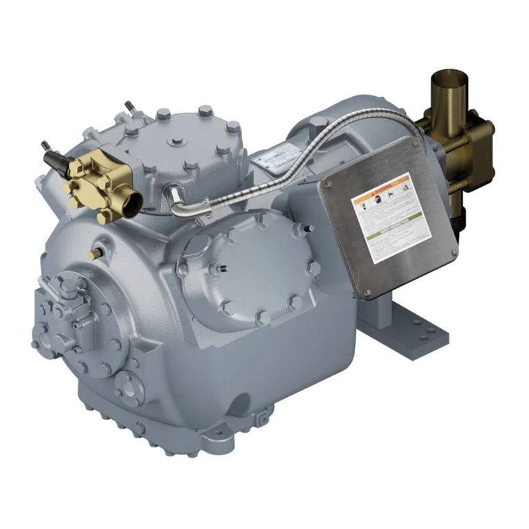
SUCTION
SHUTOFFVALVE
5/S"- t6
OIL
PFESSURE
CONiIECIION
coliTRsoL@NNECTTON
SIICTIONANODISCHAFGE
MANIFOLD@VER(FEMOVE
to8 accEss
TosrJcTtoN
STRAINERI
collTRoLcoNt{EctloN
CFAN(CASEHEATER
CASING
AGE@NNECIION
INTAKE
PLIJG
(MAGNETICI
5/6"
-t8
OAGEIONNECTION
OIL
PRESSUFEFEGULATOR
OILPRESSURECONNECTDN
5/a"
-€
OIL LEVELSIGHT
Fig,
I - 5F20;2-CylindorComprossol
@

DISCHARGE
SHUTOFF
VALVE
coryTRoL
coNNECTTON
OILFILLSR
5/6"-|3
OILLEVEL
SICHT
SUCIIONSHUTOFFVALVE
I-516'ODFGEMOVEFoR
ACCESS
TOSUCTION
STFAINEN
I/|I" IP8 OAGECONNECTION
collrRsoL
coNt{EcTroil
OIL
P-FESSI.IRECONNECNON
OL,IRESSURECONNECIION
OIL
OFAIN
PLUG
(HIODEN}
EySP_IUTAXE
PLUG
(MAGNEflc)
OILPUMP
ROTATION
ANROWS
CFAN(CASE
HEATEB
caslNo(PiPEcaPr/2"
Fp-r)
Fig.2 - 5F30;
3.Cyllnd.r
Compr.33or

S1ICTION
MANIFOLDCOVER
PLATE
{REMOVE
FOR
ACCESS
TOSUCTLON
DISCHARGESHIJTOFF
VALVE
HloH-PRESSURE
Col.lTR0L
CONNECTION
OILPRESSURE
REGULATOR
o[- DRATNPL|JG5/a"
-tB
OPENINGTOCRAN(CASE
CONTROL
OL PRESSURE
CAPACiTYCONTFOL
VALVE
CRANKCASE
HEATERCASI
NG
I
tA" tFsGAGE
coNNEc-ttoN
OIL P1JMP
ROTATION
ARROWS
fuMPINTAKE
PLUG
(MAGNETICIS/A"-E
Fig.3 - 5F4O;
4-Cylinder
Compressol

HI6H-PRESSURECONTROL
CONNECTION
coNtnoLcoNN€cTroN)
LOUI.PRESSIJRECONTFOL
CONNECTION
ONTROLCONNECTION
OILPRESSIIRERECIILATOR
CFANKCASEHEATER
caslNo(ptpEcapt/2'FpT)
MEPLATE
SEALCOVER
DOWELHOLE
SIJCTIONSTFAINERS
SIJCTIONMAN]FOLD
(FEMOVE
FORACCESSTO
OILF]LLER
5/9"-t€
CONTNOL
OIL
STFAINER
OILPRESSIJRECONNECTI
3/O"IPS
(OPENIN6
TOCRANXCASE)
!/u$i_trNrA(E
PL'rG
(MAcNErcl
otLDFA|NPUJG5/8"-t8
OILPUMPROTATIONARROWS
paEsstrRE
CONIROLSwlTCHSTU6
Fig.4 - 5F6O;6"CyllndorCompressol

DISCHARGE
SHUTOFF
VALVE
SUCTION
SHU'TOFFVALVE
CONNECTION
OILPUMP
ROTATIONARROW
I
I!
SIJCTIONOISCHAFGEMANIFOLD@VER
(FEMOVE
FORACCESS
TOSUCIION
STFAINEFANOHIOH-PRESS!RE
OILPRESSUREFEGULAMR
DIICHARGE
GAGECONNECTION
HIGH-PRESSIJFE
CONTROL
coNNECT|ONt/4 rPS a)
OILLEVEL
SIOHT
OPENINGIO
CRAN(CASE
(HIDOEN}
PLI.JGGEDOPENINGS
FORINTERCONNEC-IION
(I\OT STANDAFD)
CRAN(CASEHEATER
CASING
q
I
Fig.5 - 5H40,
,16;
+C'ylindor
Compie$ors

HIOH-PRESSURECONTROL
coNNECflON
t/1" rPS -
OILPFESSIJFEREoIJLA
PNEUI(ATICCONTSOL
coill'tEctroi t/4" rPs
OFENINOIO CRANKCASE
OILPI'MPPRESSURE
GIDDEN
CAPACITY@NTROLVAIVE
MAGNET|C5/A'-IA
SUCTIONSHUTOFF
VALVE
PLUGGEO
OPENINGS
FOR
INTERCONNECTION
{NOT
STANDAFO)
CASINO
(PIPE
CAPI/2' FPT)
CONTROL
OILSTRAINER
PLUO
5/6"-B
CONIROLOII-PRESSURE
orLreveusrcm
orass
DOWEL
IIOLE
ACCESSTOHtcH-
PF€SSURE
RELI€F
VALVE
SUCTIONMANIFOLD
(FEMOVE
FORACCESS
TOSIJCTION
STRAINEFI
LOWPRESSURE
COiIIROL
CoNNECTTON
t/t"tPS
OIL.FIILER
PLIIG
5/4"-|a
Flg.6 - 5H60.66; &Cyllnd€] Compresso6

NIGH-PREsgJRE
RELEFVALVEAND
1VANIFOLDCOV€R
PLATE
OILPRESSURE
REGULATOR
SUCTIqNSHUTOFFVALVE
3-t/a" o0F
SUCTION
STRAINER)
cot{NEcTtoNl/4"tPs
SUC'IONMANIFOLOCOr'ER
FORINTERCONNECTION
(2) CRAN'CASE
HEATEF
CASLNCS
(PIPE
CAPI/2"IFT)
DISCHARGE
SHUIOFFVALVE
3-t/8'ODF
GAGECONNECTIONS
HIGII-PRESSURE
@NTROL
LOW-PRESSUR€
CONTROL
CENTERiiAIN SEARING
FETAININGSCREW
ACCESS
COI'IIROL
OILPRESSIJRE
OII.
LEVELSIGHTGLASS
C)t
Fig.7 - 5H80,86;
8-Cylind.rCompressors

GqS
EOUALIZER
CONNECTiON
RELIEfVA-LVE
DISCHARCE
Fig.8 - 5H120,126;
l2-Cvlinder
Compressols
OILPUMPROTA'T|oN
ARROW
CONTROL
OL PRESSIJRE
CRANXCASE
DRAINPLUG
OL PRESSURE
GAGE
SHUIOFF
VALVE
{AFTEFOILFILTER)
SI]CTIONSERV
CEVALVE
OILUNE
CONNECTION)
(BEFOFE
OILFIITER)
FULL FLOW
HIGII-PRESSURE
OISCNAR6E
6A6E -
coNNECTtoN
t/4 rPS
CONTROL
CONNECTION
I/4' PSIHIDD€N)-
OILFFESSURE
REELJLAIOR
CENTER
MAINBEARING
RETAININGSCREWACCESS
lHt00EN)
SUCTIONGAGE
CONNECTION
(2)CFANXCASE
HEATER
CASINGS
{H
DDEN)-
sEEFIG.7
SUCTIONMANIFOLO
OIL
CONINOLCONNECTION
l/4"rPs
lHtDoEN).
LEVEL
SIEHIGLASS
OPPOSITE
SIOEOF
COMPRESSOR)
HIGH-PRESSUFEOILCONNECTION

Provide
spaceequat
to€ondenser
lengthfbr tube
removal
Step 2 - Receive Machine (Fig.I tuough8)
BEFORE
UNLOADING
- Check
unitnameplates
against
modeland s€rialnumbers
recordedin job specifications
Che\kall ilems
agdin.tshrpping
list. andexamine
items
cdrefull)
tordn) shippingdamdge.
lt damage
i! foundor
anvmalor
componenrha.rom loo'elrom its anchorage
trave
rra'n.ponarion
inspectorreramine
il beloreunloading
Fileclaim
immediateltwithshipping
company
foranyloss
ordamage.
RIGuNlT CAREFULLY
- checkthatrigging
equipment
can safelyhandlethe approximate
equipment
weightsfor
compressors
andcond€nsing
units.
Rig
andmoveuni'
cdrefullyto
preventdamage
IomounF
ingbrackets,
refrigerant
piping
orconnechons
Step
3 - Install
Unit
To MOUNT MOTOR ON BASE - The motorfastening
set,
availableasanaccessory
for all 5F,H
base'mounted
comDressors.
includes
motorblocks
andshims
for motor
alis;menrl
capscrews,
plate
washersand
lock
washen
tor
lan-ening
molortobasea
taperdo$el
pins
forsecuring
mo-
tor ooviion
alteralianmenii
andbeveled
ua'her\for fa=
teniigrheunir
ba"eio accessory
vibralion
i\olators
II vibration
isolatorsareused,
attachtobase
(Fig.
9) To
avoiddamaging
theisolabrs,
lift unitfromendswhen
at-
taching
isolators.
Withcomoressorand
motorDositioned
onthebase,
check
theheiehtofthevibrationisolttors.
Shimbetween
isolators
and
flo;r arrequired
tole!elcompressor
base
Whenlevel.
.ecurcvibrario;isolatorsrofloor Check
lhatbevel
washer
(Fis.9) isin place.
condenser
andliquid shutoffvalveconnection
facingcom-
Dre\sor
endof bdse.
Checlrharcondenser
overhang'sup-
_port
srands
lorsamedistanceon
eachend.
Renovesolderedshipping
capfromholgas
i.let. Topre-
ventsolderfromdrippinginto inletpipewhile unsoldering,
rotatecondenser
until
pipe
isbelow
horizontal
position.
Re-
tuminlet
toupightvedcalposition.
TishtenlowersuDDorl
.lraD'
enouqhloliftconJen\er
off
stand'..Placeupperstrap.
lo6sel)
inpo'irion
wrrh
d.lripof
Eotective
material
betweencondenser
andstrap
(5F20
and
5F30
unitsuselowers$ap
only).
TO MOUNT COMPRESSOR
BASE ON SUPPORT
STANDS
- Placecompressor
baseonsupport
standswith
2 €xtra stdps of protectivematerialbetween
top of con-
denserandbase.Bolt baseintoposition
withcapscrews
andlock washers
provided.
Stop4 - AssembleRsfrigerant
Pipingandcom-
ponents - Refrigerantconnection
sizesaregiven
in
Tablel.
COMPRESSOR
DISCHARGEPIPING - Refer to
Condensing
Unit Piping Installation
lnstrLrctions
for
information.
RLFRICERANTDRIER
- A r€Dlaceable-core
filterdrier
isrecommendedfor mostsvstemi.andisersenrial
onall
low-remDerature.v.lems.
lvldunrthefield-supDlied
lillerdrier
intheli6uidlrnelncludeashutoffvalve
ro
dermit
i$lation
of drierior servicing
(Fig.l0).
Installamoistureindicator
ondownstr€amside
of dri€r
to indicate
whendriercartridgesneed
replacing.
FELTFILTERS
- Installfeltfilter
suppliedwithcompres-
sor
insuctionstrainer
(Fig.
3 tbrough8).Remove
filteraf-
ter50hoursofoperation.
lfclean,discard
ili ifdirty, cl€an
withkeroseneor neutralspirits
andinsenfor another50
hoursof operation.
Tacunil to showdatethat
filtet was
cleanedandleinsta
ed.Figurel0 andTable
2 give
infor-
mation
onreplacementfilterpackages,
0
,P FoR|sAEoR
I us:sEoLr
1l t;i1''.,
*t*"
,g[Es 1i
\r /w\th
5H LIOUIDLINE
FROMCOND.
TOMOTJNTCARRIER
COMPRESSOR
TJNITSANDCON'
DENSERPACKAGES
- Boltthe
compressor'slowersup-
pon
,lrJp\ loosel]
(ounder.ide
of each
\uppon'tand
and
Dlace
'rrip' otprotecrive
marrial
(suchasFabricaronsEap.
i'o,irioncondin.er
on 'tand.\ irhholgas
inlelarropof
693
Fig.
10- RefrigerantFilter
Driorand
ShutoffValveAllangement
Step 5 - Instsll Multiple Compressors
EQUALIZING
LINES
- Compressorsoperating
in paral-
lelrequireinterconnecling
linesloroiland
ga.pre*ureequal
ilarion.
Specialhandholecover
plates.
equipped
wilhrapped
holesforequaliringlines.
areatailableasoplions
forsiTe'
5F40and5F60,aswell asfor sizes5H40through86com-
pressors(Fig.l1). An oil floatsystem
isanacceptableal-
lemativetoequalizerlines.
Fig.I - TypicalVibration
lsolstorMounting
10

5H120
and
|
&.1q9!op!q$qE
include
taclory.supptied.
lapped
coverprare.
otr these
compressors.
u\e
onlylower
connec.
I'onlor oil equalization(Fig. tt). Connefi
eas
eoualirine
ljnetoflangeconnecrjon
sho\^n.Matine
jian-ae
loi l!-in:
lineisCarrier
Pan
NoiDK24CA7t2
(Mueei pan
No.A
5151);gasket
PanNo. isDK29GA005
(Mueerparr
No.
A-5152).
5F20qld 30 Comoressors
haveno special
tappeo
cover
plale,
Useopening
for
oilsighr
glars
roauach
lhet!&m.
rrne
lor
ga{
ando'lequalization
(Fig.
t2).
Accessory
pack_
ageNo.06DAq00072.provides
two rin. Iine
adaprers
to
Uriao Inlo
rhe
lrghlgla(s
opening.
tf addirionat
equalza_
tron.rs
destred.
run
a s-in.
lin€rorheoit_fitter
pll;g
con_
nection
(Fig.1and2).
GAS
EQIJALIZER
COJiNECTION
r{ ootaloe -
(sr-I2o-t26
oNLY)
Fig.11- Spocial
Hand-Holo
Covorand
Equall2er
Connoctions
(Typical)
Fig.
12- Equalizsr
Connections
{5F20
and
3Ol
ORIVE
AND
SEAL
END
SCREW
FITTING
INTO
0PENll'lcFOR
OIL
LEVEL
srcHl GLASS
FOR
l-tl€ "
EOUALIZER
LINE
OILLEVEL
Tablo1 -Physlcal
Data
COMPhEAIOF
UNTIAI{O
COND€I{SINO
UNII
su€. i.e, pl*r€ d'horerridt
@rw6on*a,on sss,o aa; di.;i;,s. ;;;
I
Oi ll@ 'als.
{gpm)
10'
5H12-c}t:
4.5
gpm
* F TslJa r€voGtr
g
oit
pump.
(rn
o.D.)
'li?Ir?l "llPP.":i',i"":ll"f,l,
t-ihvsicar
oaiarabrs
e6a!o!6suclon
p*e ll:'rel.ard.@ildondon$c
AIorh€.5rH@nd6ns€,sa€sne.aldrLbo.
Noc@ensordo'Es€ep&tty 30%
,ur6d
{ rhxqu,o
€l1a€,ant6.90F.
1.Ollll@Ere sft.nomtndtoipump
cap.clty
/ un*Dry $rbr ms TE4uat'6.1 dnd1T€o€,ar'
ot assoconde.
1sG3s5(adju6r6b
€lnom
nal
60-l50ladlr6tabtot
culout,300
1 15culin zto i 10
20in.Hs-v_ac
to60psis(adjusidb
e)
curoul,
soI 4 culin i2o J 6
CONOENS€B
DAIA 5F3oii o27 09Fi. 00nH. 127
72.8 a2.o 199 216 257 327
B-502 15.0
, 335
psig
" P>e | 250
psg
3;".T$,X'93ili,;i""ji"f*8['.$]3;
.*,",".
I

Table
2 - Suction
(Feltl
FilterPackages
COMPFESSOR FILTER
PACKAGE
PAFTNO.
5H40
throuqh86Complg$gl! Drainoil belowlevelof
pump.endcover
rFig.5-7\.Remote
pump-en'icn\erloex-
po'e
oil
pump
cover
incenleroi
mainbearinghou'ing
Ro-
iateort iump cover180degrees
andrepld.eit Replace
oumo-endcoverand
re\er.eexlemal
arro$to malch
ne\r
direclionof rotation.hoper directioncanlaterbechecked
withoutremoving
pump-endcover.
5H120
and126Compressors
(Beg;nning
S/N1086J
-)-
Supplied
withautomaticatly
reversing
oil pump,
el;minaG
insneedfor adiustment.
For5H120
and126
rnodelsbuilt
be-foreS/N1086J--,follow sameadjustmeflt
procedure
out
linedfor 5F
compressors.
5F40
5H40,46
5H60,66
5H80,46
5H120,126
5F60-A352
5H40-A382
5H60-4382
5H80-4382
5H120-4382 e,
2.
3.
Step6 - MakeElectrical
Connections
GENERAL NOTES
l
l-dcton
$irinqcomplie'
si$ \atronalElectrical
Code
,NEc; An\ fleld
modificalion'
oradditions
mu.lcom-
plywithaliapplicable
codes
4.
5.
*For
controlcircuit
informalion,
refer
toAccessory
Con'
trolPanel
Installation
Instructions.
ll controlcircuil
power
is
'uppliedfrom
aseparale.ource.
ratherthanfrom
; Fansformei
bring
Il5{ power
rhrough
aield-supolied,
l5-amp
d;connect.
incomPliance
with
NECSeciibn
440-14
{d;connect
mu\t
beinsighr
from
andreadily
accessible
fromunit).
ODencontol-power
disconnect
only
whenservicing
unit
Ciankcase
heatersmust
remain
energized
whenunn
rs
notoperalmg,
"Faltory
wiringisfor single
Pumpoul
control Donor
u'eoumooutcontrol
onequiDment
used
qilh Dx cool-
er..wi'ing labelshows
fdld connecrionJ
u'ed
wirh
DX
*Contactor
C2is used
with208-v
motors.25through
60hp,and460-vmotors,
50
through150
hp
7. *when field interlocks
are
used,rcmove
jumpers
be-
tween
terminals
3and4,andbetween
l€rminals? and8
onTB2.
*Refes
toconprcsor
unitsand
condensing
unirsonly
ATTACH POWER
WIRESTO COMPRESSOR
MOTOR
- Attach
Dower
wiresin accordance
wilhmotormanufac-
turer's
insiuctions
andincompliance
withNECand
appli-
CHECK MOTOR ROTATION - Beforeconnecting
mo-
tor
tocompressor,
checkdirection
of motor
rotationRotQ_
tion mustbein sane directionas that indicatedb! ato\t'
onconpressor
p np corer(or on
plateatached
near
pumP'
end
bearingho sind. If direction
isnotthe
same.reverse
motorrotation
byreversing
any2 Power
leads
tomotor.
lf roradonof oil pump
isreversed,reversedirection
of
pumprotationarrowas
wetl.At thattimemake
thefollow-
ingadjustments:
All 5FConpressors- Remove6capscrews
ftomoilpump
co\e|Fig. I 4,. Donordamage
ga"kel.
Rotat€
cover180
degreer
andreplace.
Arrowarlopof oilcover
willindicate
newdirectionof rotation.
INSTALL CRANKCASEHEATER - whe heaterto re-
layorselofnormally
closedauxiliar)
contaclson
compres-
\or.raner
rode-energize
it whencompres\or
i\ operallng
Removerubb€r
plug
fiomcrankcasehealer
casing
(Fig
l-8,.and
insenhaaler
elemententirely
intocasing
Ele-
mentshould
fit snugly,
notloosely.
Wireto conply with
applicableeleclrical
codes.
Whencrankcase
beater
isinstalled.system
canbeoper'
atedonsingle
pumpout
cycle,
unlessused
withaDXcooler.
Tab)e
3 listscrankcase
heater
packages.
Table4 shows
correspondrng
rela)'. U.eol 2 hedter.
ona 5H80
rhrough
126compressor
requires
onl,onerelay
Conrrolcircuit
vohagedetermines
relaycoil
voltage.
This
voltagemustbesp€cified
whenordering
relays
SeeAccessory
CompressorCrankcase
Heater
Installa-
tionhrstructions
foradditional
informadon.
Table3 - sF,HComprossorCrtnkcase
HgaterPackago
lf rhe.Decialeasket
between
oil Dump
cover
andoil
pump
is'damagia.
replace
uithconed
ga'l'nonl) Che{k
6il pressure
immedi;tely
afterstaning
compre.'or
5H80,06,120,126
PACKAGE
NO.
-20--381
.5-H-.40--381
-5-H-40--391
-5.J..40--281
-5-J-40--291
Table4 - CJankcase
HeatelRelay
(60
Hz)
CONTNOL
CIRCUITVOLTAGE
12

Step7 - Check
Compressor/Motol
Alignment
BELTDRIVE SeeAc€essoryBeltDrive
Packageman
ualfor installationandalignment
instructions.
DIRECT DRIVE - Installandaligncornpressor,
coupling
andmotor asdescribed
in manuaifor F6xible Coudlinsi
1orDirect-DriveUnits.
HOTCHECKAND DOWELING Tohelpmaimain
align-
ment, andto ensueexactrepositioning
of themororafter
servicing,
the
motorandcompressormust
bedoweledto
tbe
base.Installdowelingonlyaler motorlco pressor
align-
ne t ha: been hot checked(checkedafter the com-
pre.\sor
haswarmed
uptooperulingtcnferuatk an?rtN-
Afte;
hotcheckand
shile
componenr\dre
\nl JropeF
dung
tempenture.
drillandream2hole:
rhroughdiagondll).
opposite
motorandcompre\sor
leerdndrhe
ba\e.U,e a
e ,-in.drillandano.6taperreamer.
Secureth€motor
and
compressor
tothebase
with
theno.6x 2%,in.
raperdowel
pinsprovided
in themotorfa$tening
set.
Coatthedowels
with
whitelead
orotherlubricant
topre-
vent
runing.
andlaprhedowelLShrly
inlo
posiuon
ro rhdl
7,6
of taoerisleftabovethemoLorfoot
Checkthatall dowels
ar€tight and
thatrneyoo nor
Step8 - Assemble
WaterPiping
- seewdreF
Cooled
Conden\er.lnrrdllarion
Inslructron\
andWarer
Cooled
HeadsInstallationInstructions
fbr infomation.
Step9 - Prepare
Lubrication
System
INSTALL
OPIIONALEQUIPMENT
- Consultlocal
Car-
rierrepresentativeforinformanon
onrhese
accessorieg.
Oil Fiher - Orlfilrertor5H40rhrough
86compressors
is
rvailable
asseparaleacce*or' package.
Refe'
lo Acce\-
$ry Oil Fiher
PackageIn.lallatronIn,truclion.
lor insral-
If anaccessoryoil coolefis al$ install€d
(see
below),
pipe
oil fillerinlo
s).lem
as
\hown
ondrasram n Acce+
sorv
Oil CoolerlnstallarionIn\rrucuon\
Oil Cooler - Refer
toAccessoryOil CoolerInstallation
Instructions
includedwiththisaccessory
package.
Adjust
water
flowratethrouahoilcoolertomai'ndint0-0
to tiOF
oiltempemture
retumi;gtocompressor.
Se€ScheduledMain-
tenance,page
17.
Oii
Separator
- lfoil separ
orisusedin\',lernpiping.
pipe
oilretumlineto
compressor
\uction
line.
Tominimize
possibility
of floodingcornpressor
withoil, oil retumline
diametershould
notexceed
L/a
inch.
Inaddirion.tine
should
have
manualshutoffvalve
to tkottle oil flow asr€quired
and
toisolateseparatorforservice.
CHECK
OIL LEVEL - Checktharoil level
isvisibleat
c€nter
of compressors;ght
glass.
Compressors
thatuseop-
tionalequipment
suchasfil|er,
cooler,andoil separator
da-
sc"ibed
abo\ewill require
aqrearer
oilchirse
lhanli\redin
Table4.Recheckoille!eldfte-
operaring;np,r*ur.
RECOMMENDED
OILS
- Whenadditionat
oilora
coln-
plete
oiichang€isrequired,
useonlythe
Carlyleengineer-
rngdepanmenr
approred.dehydraled.$dx hee
relrigera-
tionsraoeoilsnotedbelow.
IGIPetroleum
Specialties,Inc.
IGI Petroleun
Specialties,Inc. .......
Cryol150
150wirh
addirive
Syn-O-Ad
(8478)
(Akzo
Chemicals,
Inc.additive
Witco
- Hi ambient
aDDlicar;on.
300viscosity
..........
..............
Suniso4CS
Texaco,Inc. ..... WF32-150
ShrieveChernical
Co. (synthetic)
Zerol150
Mineral
oil and
syntheticoil havedifferent
unarac@ns-
tics.One
isnotnec€ssarily
betrerrhan
theother.
Somechar-
acteristicsof themineraloilshavebeenfouno
to Demore
favorable
foruseinsomeairconditioning
andmedium
rem-
perarure
appucatons.
Approved
compressor
oilsareavailabte
fromauthorized
factorypans
outlets.
Theoilsrecommended
aE fullvcorn,
parible
wirh
eachorher
andcanbe
miredinany
prop;ruon.
PREPARE
FOR
INITIAL
START-UP
Evacuate,
Dehydr€te
and
LeakTest trrcenurere-
frigerant
systemasdescribed
in CarrierSrandard
Service
Technjques
Manual,
ChapterI, SectionsI 6 andl-7.
LEAK TESTING
Prgfened
Method - Charge
thesystemto 10
psig
wirh
refrigeranr.
Adddry
nirrogenor dryair
(DO
NOI USE
OXYCEM
unril.y.ren
prcssure
a t50psjg.
Check
forteaj(s
wirh
a halide
orelecrronic
leakderector_
AltemateMethod - Charge
rhesystemwith
drynirrogen
or dry air(DONOTUSEOXYGEN)
to 40 psig
anduse
soaD-bubbletest
tofindlarpeleaks.
Do noa
us€compressor
to builduppressure.
Do not
overcnarge
thesystem.
R€fligerant Charging - Lre rhe
srght
glass
method
tochargerhe\'slem. SeeSecrion
I-8 of Carrier
Srandard
Service
Tecbniques
Manual,Chapter
l, forderarb.
Charge
thelysremto a clear.rghr
glass
while
holding
saluraledcondenslngprE\\ure
consLant
dl 125F for air_
cooled
systemsor 105F for wateFcooled
svstems.
Add
additional
refrigerant
to fill condenser
subco;br
coils,if
5F,H
CONDENSING
UNITS
- Afr,er
aclearsight
gtass
is
oblained.
addcharge
unrilliquid
refrigerant
reache\the
con-
oenser
quro
tevettest
(ock.
5F,HCOMPRESSOR
UNITS - Seecondenser
datafoi
additionalcharg€
requirements.
START.UP
Preliminary
Steps
1. Energize
crankcase
heater
for at least21 hoursbefore
2. If control
transformer
isnot
used.oDerateelecncar
con-
rrolcircuir$irhmain
power
\wircli
OFFroen,ure
lhal
iield
connecrions
havabeenproperty
made.
3. Install
feltsock
filterforthefirsr50hours
of conpres-
soroperation.
Remove
andinspect
thefilter,clean
ir if
requiredand
replace
it for anorher50hours.
Renove
sockwhen
sys@m
isclean.
(Not
applicabtefor
5F20and
5F30units.)
4. Cbecktha|motorrotates
in dhectionthatthenow on
rhecompressor
oil pump
cover
indicdre,.
Reierto In-
srdllaaon.
Step
5.underCheckMolor
Rorarron.
5. Checkthat
oilfills/3to 7,ofthe
compressor
sight
glass_
6. Openwater
supply
valve
to condenser.
Operprcssure
linevalve
of water-regulating
valve
(if used).lf com-
pressor
unitisequippedwith
air-cooled
condenser,
rum
oncondenserfan.
l3
........Suniso3cS

1.
L
Back:edt rooenr compressor suclion and diqcharge
.ervice
\al!es.Openliquid
line
valveatreceiver'
Start evaporator fan or chilled wat€r pump
If an accessoryoil cooler is provid€d. adjustthe water
flow asrequircdto maintaina 100F to 120F crankcase
relum ol tempem$re,
A- RANGEADJUSTMENTSCREW
fu"- o,rrror"r,o.oo,,aaa,
A-RANGEADJUSTM€NTSCREW
4-"-o,oo."unt,o.- AOJSCREW
PENN
A.RANGEADJUSTMENTSCREW
@*u-o,rr.".n.o. oo,
TOP
SCREW
Scr€w
Alals€8orlowelsbottr
cutoutandcutlnpoln|8
byalik€amount
RanoeandDif€renlial
Bcal6sareonlh6lront
ollho
swilch
HldhPrcssur€r
s€l cubut polnlllr3l,wllh3cr€,w
ai th€n s€l cutl,
- point
wthsarowA.
LowPrgssure:Sstcut-l, polnt
llrst,wlthacrcw
Ai th€nsoioulout
point
wlth
ac€w
B.
LOCATION
ANDADJUSTIJENTS
Fig.13 - Hlgh-and Low.Pre$ur€ Switchos
Foradditionalinformation,
seeOil SafetySwitchAcces_
soryPackage
lnstallationInstructions.
Adiuet
CapacityControl
(it requir€d)
5F20 AND 30 COMPRESSORS
- Refer to Capacirv
Control Valve Installation Instructions for additionat
information.
5F4O
AND 60. AND 5H4O
THROUGH 126COMPRES-
SORS
- Determine
th€refrigerant
usage:
It thcs\ en it touscR-12,rcpLa.?
theI I'lb ranSead
ius"tment
iprina
tFie. I5
) with
thi 7
'
lbspring
ruppliedwith
ronDre\sor.A chans€
in lS82 reversed
which range-
adjuiring
springacu"romer
received.The-R-22/R-502
spring
is no$ rtandrJd
with Uecompressor'
seernstrucuonlag
for springreplacement
procedure.
TSHAW
Start Compr€ssor - Close
main
power
switch
sup-
plying curent to thecompressor
motor.
lmmediately
recheck
orlleveland
chect
oilpre.sur'he\-
surelhould
eiceed
suclion
pressure
b) 45-55
pri 4.r/f?ct
pres:neisnotteached
in l0'12se,ond..
\rcf.onprcsor
imnediarel\
andcheck
oilPunP
Ifan) safety
dericelhut5
down
tht compressor.
donot
reselthe
conuolmor€
thanonce
beloredet€nrurung
cause
e,
Check Control Operation - RefertocatrielSran-
dardServrce
Techniques
Manual,
Chapter
2. forcomPlele
instructions
onche€kingel€ctrical
comPonents.
HIGH-ANDLOW-PRESSURE
SWITCHES
- All5F and
5H unitsexceDt
5F20and30 have
factory-installed'
auto-
maric
reset.hiih' andlow-prcssure
ssirhes (Thes€
swilches
areararlableis accessorias
for5F20
and30units
) Figure
13illustrates
adjustment
proceduresforboth
switches
Check High.Pl$9ure Switch - Thronle
thecon-
denser
wateionwater-cooledunit
or block
theairflow
on
arr-cooled
unit.allowinghead
pressureto rise
graduall)
Comprerror
shouldshuaoff
trilhin 15
psi
of cutoul
value
listedinTable4.Nowreverse
procedurc;
compressor
should
stan
within10
psi
of cut-in
value
given.
Check Low-Prgssurg Switch - slowly close
lhe
sucrion
rervice
valve:suction
pre.surewilldecreaseCom-
Dressor
\houldshutoftwithin4
psiofcutout
value
listedin
Table
5.Reverse
procedurelcompressor
should
stafl
wirhin
6 psi
of cut-in
value
given.
i
Tablo
5 - typlcal Plossuro
Switch
S.ttings
FEFBIO.
ERANT CONOENSEF
PRESSURESTAT
Hlch
(p.tg, )
cutoul Cuth
12 175
225 95
145 16
l6 76
76
2AO
325 200
245 36
36 96
502 2€0
325 200
245 45
45 105
105
OIL PRESSURE
SAFETY SWITCH - To check' move
contact
arm at left sideof switchforward(Fig. l4) Com-
pressorshouldstopin approximately
45 seconds.
lfcomDressor
conlinue'
lorun.checl'lhe
winng
to
safery
s$itch.Ii wiringi( conecr.
.witchisfaullyand
shou'dbe
replaced.
After completing
test,wait 3 minutes;thenFessrcstart
buttonon front of safetyswitchandresEn compressor.
Checkoil levelin compressor
sight
glassafter15-20min-
ulesof ooerarion.
tf theoil levelis Io$. addoil by rhe
medodraescribed
inCarrier
SlandaJd
Senice
Technique(
Manual,Chapter
I, Section
1-Il.
\
HIGH
-
PRESSURE
PRESSURE
swtTcH
5H MOUNIINGARRANOEMENT
SHOWII.
t4

RESISTANCE
(REFER
TOUNITLABEL
llIGH.PRESSURE
CONNECTIONTO
Fig.14- OllPre$ureSafetySwitch
CONTROL
CONNECTION
An extemal
adjustingstem
(Fig. 15)s€tsthecontrol
point
Guction
Fessureat which first stepof cylinderunloading
occurt. Thecontrolpointis adjustable
asfollows:
R-22andR-502 .. ... .......... ...... 0 to85Dsis
R-12................
.... .........0ros0
bsig
Onefull clockwisetum of adjustingstemwill raisethe
contlol
point
approximately
6 psig
withR-12,or 10
psig
with R-22and
R-502.
Controloil pressure
is anindicationof cylinder loading
condition(Table6). Referto Fig. 3-8for locationof con-
trol oil-pressurcconnection.SeeAccessoryUnloaderPack-
ageInslallationInsfiuctions
for additionalinformation.
See.Fig.
16forCapacityControlSystem,andFig.17for
umoaorngsequence.
Table6 - ControlOilProssurostor
CylinderLoading
.nd Unloadlng
COMPRESSORSTEP" APPFOXIIIiIATE
CONTFOLOILPFESS.
(p!lg)
Loadlng Unlo.dln
5F20 119.8
5F30 1
230,0
19.8 20.2
13,0
5F40,60;
5H40,{1,
60,0€,80,
86,120,126
1
2
3
30.0
24,0
23.0
20.0 r6.0
12,0
9.0
toapaclly
Controlreducllon.l6pE.
FPNEUMATIC
@NIFO!
tSNOTUSEDITI]ISFOFT
MUST
8EVENIEO To AdjustConholPoint
l. Imposeananificialloadonthecompressot
untilsuction
pressure
exceedscontrolpoint.
2. Slowlyclosesuction
valve
io lowercompressor
suction
pressurc
rocontml
PorntPressure.
3. Whenat control poin! pressure,
tum extemaladjusting
stemclockwbe until fint stepof unloading
takes
place,
asindicated
by,changesin controloil pressure.
current
orawanosounool compressor.
Control
Doint
isnow
set.ReoDensuctionservicevalve,
Compresso;
will befullyloaded
;hen sucrion
pressure
is3
psig
(4psig
with
R-22andR-502rarrvccon$ol
poinr.
and
will befully unloadedwhen
suction
pressure
is4 psig
(7
psig
$ith R-22andR-502),?loa conEol
poinl.
5F20AND 30 COMPRESSORS
- Two capacityconrrol
packages
are available
as accessories.One is suitable
for_R-12applicationsithe otherfor R-22 and R-502
Theadjustingstem
(Fig.15)
is shippedin a backseated
(fully
countercloclwise)
positjon.
Compressorwill be
fully
loadedunderallcondirions.
Adjuslthecapacitycontrolser
poinlbylhesame3-step
procedule
describedabovelor 5F,()
and60.and5H4Othrough126compressors.
SPRINO
OETAILS
ft',r**ffi'mi*
'WhencomDrcssoris r€c€iv€d.
lhe caDaciv
conlloladiustino
sl6mlvlllb6backs6at6d.
(Compr€ssor
wllib6'irllyload€d
Jniln all
Fig.15- Cap.cityControl
V.lve
15

rs
NoTusEq
THts
NI-IT
ELEMENI
Cylinder
Unloading
Sequence
ELEMENTS
DR
LLED
HOLE
Fig.
16- 5eH Capacity
Control
Systom
{Exc6pt
5Hl2O,
126)
5H60,66
5F60
Fis.
17
-
o
o
o
5Hr20!r26
16

*t
+2
-
LEFTSIOE
ConnocllonloOllCool€r
(Sls6v€
Localon)
OllPumpPresslre
(Both
Locations).
Us€eitherfor
Hlgh-SldgOilPr6ssur6SwtchConioclion
SCHEDULEDMAINTENANCE
5F,Hcompressorandcondensrngunit\
provide
longIife
anddependable
service
qhen
properl'
operaredandregu-
larlymaintained.Establisha maintenanceschedule
based
onfactors
suchasope.atinghours,loadconditionsandwa-
ter
qualjty.
Maintenanceschedules
listed
inthiss€ctionare
offer€d
as
guides.
Modifythemasneeded
to sarisfyindi-
vidual
machinerequircments.SeeFig.I8forimportant
com"
pressor
servicelocations.connections.oil cool€rsleeve
Check Lubrication System - Always
checkcom-
pressor
oilleveibeforestaningunil.lfoil isrequired,
record
date
andamountadded.RefertoFig. I
-8forlocationofoil
fiher plug.Table
1 and
Slep
9 showspecified
lypesand
quantities
of oil.
Useofaccessoryoil separatorrequiresadditionaloil.Oil
leveland
separalorfloatvalvemovementduringinitialcom-
pressor
operation
should
agreewith instructions
furnished
with theoil separator.
3 - ODeninoloCrankcase
(Low.Side
OlPr€ssLio
Sivitch
Conn€cron)
Fig.18- Typical
5H40through5H86
CompressorPump-EndConnections
F]IGHTSIDE
I - Pne0mallc
ConlrcConnecron
2 - Capacily
ConvoValv6
3 - Ol Puni!FolationArow
4 - capac
\; convololPr6ssu€
5 - OllFlllPlus
OIL FILTERMAINTENANCE- A bleed-type,high,
pressure,
disposable
filteris availableasan
acc6ssorylor
5H40
through5H86compre\\ors
(Frg.
l9r.Replace
oilfrl-
lerafterthefirsr
50hoursof operalion,
orwhenever
rhe
oil
ischang€dorbecomes
diny.
Check
yearly
for cloggedfiher. indrcaredby a greater
thannormaldifference
bel$eenoil Dre.\ure
aheadof filter
aodafier-liller.
when
rhkdifferenceexceeds
5psig.
change
l. Closeoil-line shutoffvalves
on ea€hside of filter
(Fig.
l9).
2. Disconnectoil lines
atfiherconn€crions.
3. Loosenfilterbracketiremove
andreplacefilterbody.
RefertoAccessoryOil FilterInstructions
for additional
Thefull-flow
oil filter,on5H120
and5H126compres-
soh
onl).conrajn\areplacerble
canndge.Replace
lhefil-
ter
cdnriJgealterrhefrsr 100
hour\ol compre\sorope'a
tion.After
the
initial
fiiterchange,
check
yearly
for filler
clogging.If the
pressure
difference
acrossthefilterexceeds
5 psig.
pump
downthe
compressorandthenremove
rhe
canridge.Figure20
(B)
illustrates
completefillerassembly
(not
showninFie.20tAl).
t7 693

W}lencranlcase
oil temp€raturefalls wirhin rhe 120to
135F range,tbeshaftsealhousingtemperature
shouldbe
approxinarely140ro 150F. Shafrsealhousingtempera-
turesabove170F maycauseshaftsealto agerapidly, and
hardenandcrack.Therefore:
lfshafi
sealhousinstemDerarur
e\ceeds170F.STOP
THECOMPRESSoR.
DONOr resranuni;t
rhe
(au5(
of overheating has been identified, and the condition
Fig.19 - Oil Filter AccessoryPackage
{5H40
thloush 5H861
CHECKOIL AND SHAFTSEALTEMPERATURE The
normaloperating
temperatureof theoil in thecrankcase
rangesfiom 100Fto 135F when
fullyloaded.Donot
per-
nit maximum
oiltemperaturetoexceed
150F.Conditions
und€rwhi€h
suchexcessivetemperaturescouldoccurin-
cludesituationswherc
thecomprcssoroperatesin a fully
unloadedconditionforanext€nded
Deriod.becausethecom-
pressor
would
notbeabletoremoveallof theheat
gener-
atedbycompression
andfriction.Insuchsituations,usean
oilcoolertomaintain
safeoperatingtemperatures.Referto
5F.HAoplicationDatafor moreinformation.
OIL COOLERUSAGE
- Theaccessory
oil coolermain,
tainssafe
operatingoil temp€ratureswhenl
l. Applying
longstroke€ompressors
(5H46,
66. 86 and
126).For
addedreliability,anoil cooler
isrequiredon
alllongstrokemodels
regardlessof operatingrange
or
lype
of reftigerant.
Additionalheat
of frictionfromex,
tended
piston
lravel
onlongstrokemodelsincreases
oil
2. Thesuct;on
gas
becomeshighly
superheated
(Table
7).
3. a. Th€
compressionratioexceeds
5rl onR-22systems.
b. Applicationdata
indicatestheneed
for anoil cooler
forR-12andR-502systems.
The€ompressron
rato
can
bedeterminedfromthefollowing
formula:
Absolule
Discharye
Compression
Ratio
=Absolute
SuctionPressure
rl.!{ |
(Auto.-Rev€rcing)
B
(Manual
Revercang)
*tle H-
tFig.20 - OilPumpandFilterAssembly
(5H120,
126)
l8

Table7 - ActualSuction
Gas
TemperatureLimits
(Fl.
R-12,R-22,A-5O2
SAT,SUCT
TEMP
(F) -60 -40 -30 -20 -10 0ro50
SUCTION
GAS
rEi,tP
{Fl
F.t2 35 45 55 65 65
F.502 25 35 45 55 65 75 75
NOTESI
1 Forcontinuousoporalion
wilhR-22:
Cader sF.H SpecificdPads
intercbangeabiliry.
3. Beforeservicingcornpressor.
5.
Startcompressor,closesrctionservicevalve.aDdre
ducecrankcrse
pressure
to 2 psig.(Bypass
low pres-
surestntwith jumper.)
Sropcompre*or.clo.edi.charle
.en
ice
\
dl\er" i'n
Bleed any rcsidual refrigerant. Drain oii if
lisr for compressor
pan
pump
downtherefiiger-
J
2. Do nol op€ralo
unloadersal saluraled
al or below0"Fwilhour
prior
approv8
Engnee.ing.
4. Thecompressoroperates
fuUyunloadedibr prolonged
periods.
Under
theseconditions,suction
grslevelsnray
no!sufficetoremolelhehe,rtof conlprcssionandtiic-
t;on.
This
conditioncanoccur
inanyapplication.butis
mostlikelyin lowtempcrrture
systemsor variable-
volumeapplications
thrtusehol-gasbypatttomaitain
specifiedconditions
underlowevaponi('
lord.Rcfcr1o
5F,HApplicdion
Dutatbraddilionrlinlirrnlrtbn
Adjustwaterflowralethrough
oilcoolcrtonlaintain100
ro 120F oil temperature
returningto compressor.Crank'
crsetemperaturehust rcrnainbclow140Fishali
sealtem
perature
atthe
sealhousinglhould
notexceed170F.
T:rble$
8 and
9 listmaximum
worknrg
pressures
lbr oil
lud water andestimated
wrter llow ruteslbr varous ol
cooler/compressorconrbintions.
Foradditiontrlinli)rnrA-
tion,seeAccessory
OilCooler
InstAllati(nrlnslrucli(nrs.
TableI - Oil
coolerMaximum
WorkingPressure
Table
I - OilCooler
Estimated
Water
FlowRates
Afterdislssembly,clcanall pans
with solvenl.Usemin-
eralspirits,white gasoline
or naphtha.
Beforenssenbly.coatall parls
wilh compressofo'l and
cleanandinspectall gasket
sudaces.Rethce all gr!
ketswith new, lactorynradegaskets.and lightly cort
with oil. SeeTablc l0 ior lorquevalues.
After rcrssembly.evacuateconrpressorand open ruc
t;on anddischarge
valves.Restartconrpressorlnd ad
just refiigerrntchargc.
J
5H40-66
5H80,86
5H120,126
'Flow
ral€bas6don80
Fenteing
wai€r,
Check Water-Cooled Heads - To
prevent
oilbreak-
downandsludgeformation,
thedischarge
gas
temperature
must
remainbelow275
F.water-cooledcylinder
heads|rre
avaihble
asan
nccessoryfor this
purpose.SeeAccessory
water-Cooled
HeadPackage
InstillationInstruclionstbrad-
ditional
information.
SERVICE
Seryiceandrepanof Canier
reciprocatingcompres$rs
nndother
refrigeration
componentsshouldbe
pefonnedonly
by fully trainedand
qualifiedpersonnel.
ServiceNotes
l. Compressorcompone.ti
areshownin nornalorderof
removalfromcompressor
(Fig.
2l and
22).
2. Forr€placementitems,useCanierspecified
parts.
See
LubricationSystem
OIL PUMPS
5Fcompr€ssors.Scc
Fig.23 nd15.
5H40-86coDpressors.See
Fig.24 d 25.
5H120,126compressors,
witha ldnrricrllyreversing
oil
pump.
S€e
Fig.20(A).
5H120,126
cornp.essors,wilhmrnurllyrcvcNingoil
purrrp.
SeeFig.20(B)rnd26.
5H120and126CompressorOilPump
History Reterence
NOTE]By ls6li,lh6aulomaiicrove.singoilpumpcannotbo nslaled nplaco
ollhe manuaLyrove6ing
oil
pump
orv cev6reaTri6
complel€
b€arngrroad
assdmblywlh ih6 o pump
laulo or manual)s ni€rchanoeab6as a com
MANUALLY
REVERSINCOILPUMP
Oil Punrphrsnecti{'r Scc
Fig.
208. 23.ud 24for5F
and5Hnunuallyreversirgoil
pumps.
Alsorefcr
to
5H120,
126auto.
revcrsingoil punrpscction.
Drainoil belowlevelol punpendbcnringhead.Re-
movebearinghead.Completeend-bellassemblyDuslbe
renroved!oaccessbeariDgheadassembly
wi!h
oilpump
on
5H40through
86 nn)dels.
Checkoil pumprotorfor end
phy. M.rximunrallowlblemovement
of rotoris0.0025.If
thereisexcessiveend
play,
repositionoil pump
bushingin
bearingheadasdescribedbelow.
Turnrotor.lf lhereis morethana slightdrrg, remove
punrp
cover
xnddisrssembleoil pumpcheckingall parts
for wearanddamage.Inspectoil pump
bushingfor scor-
ins.Replacebushinsif scored.If bearing
headis scorcd,
replace
completebearingheadandoil pumprssembly.
OilPumpBushinqInstallation
- SeeFig.25
rnd16.Po
sitionihebushingoil groove
attop
(running
fronl l::00 to
6:00)whenthebearingheadisinstalled.Pressnewbushing
intothe
pump-end
bearinghead
fromtheinnersideof thc
headwiththe
chrmfered
eDdenteringfirsl.
couPREssoR
1.2
11/2-3
2'4
l9

Oil Punp
Bushing
Posidon
-r " si.zo-eo
-a snlo'86. See
Fig 25 Place
0 001-in
' - il'iir* rlra t^u;.ated
chimaEainsr
burhing
andin-
sull oumo shim
between
bu'hing
and
o'l pump
ro-
lor.Comilere
a$embu
of oil pump
w'$ ga'K€rano
o.!ff"iio,ttu..* t', 26Plac€
0015-in
(|d-in
rshim
- i"i*-.* j"n in'ei and
oil
pumpco\er'
compler€
iii.'iiivll;tt il.p -a puinpiover
wlttrout
using
2. Tao
burhins
with
luilabte
cylin&ical
posirioning
roor
to
seit rtagaiist
shim See
lypical
arrangement
shown
rn
Fig.25.
a. 5F20-60
and
5H40-86.
See
Fig 25 Disa\etnble
oil
- "".o *a t rno'. "ttlt Reassemble
orl
pumpCheck
ior
brnding
o. !iizo,tr[. Remov€
oil pumpcover
and
shim
Reassemble
pumpco\ersirh gaskel
(becK
ror
binding
tn.lall
bearinq
headon
compressor'
Line
upltrng
on
orl
oriip 'J.i"f,"t *i,t' sor inendot crant'hafr check
bil pumpfotProper
direction
ot 'otaoon
Refill
conpre..or
oil toproPerlevel Ot(er\eoil pres-
."* i"t." it ti"g *.p*tsoi conect
oil
prcssure
'hould
be
45-55
psigabove
suchon
pressure'
3.
5.
t,
\
i5"tt'**ttuoo
r'n@+>.-"/ C\LINOER
cEADGASkET
a
€;g "u",,o,,o",
BEARING
HEAD
ASSEMALY
INNEF
SEAT
ASSEMALY \. olsc
ECKVALVE
END
BEARING
."-i- \ KE!
\\)-
- [ b.,^9"
HAND-HOLE
Fig.21 - 5HCompr€ssor
External
Com
mpononts
This manual suits for next models
13
Table of contents
Other Carlyle Air Compressor manuals

Carlyle
Carlyle TS Series User guide

Carlyle
Carlyle 06ZCE1H3AA06013 User guide

Carlyle
Carlyle 06CC User guide

Carlyle
Carlyle 06T 033 Series User guide

Carlyle
Carlyle 06E Instructions and recipes

Carlyle
Carlyle 06D User guide

Carlyle
Carlyle 06D Instructions and recipes

Carlyle
Carlyle 06D User manual

Carlyle
Carlyle 06D User manual