MPS MP2672 User manual

User Guide
MP2672 Evaluation Kit (EVKT-MP2672)
MP2672 Evaluation Kit User Guide rev 1.0 MonolithicPower.com 11
10/15/2019 MPS Proprietary Information. Patent Protected. Unauthorized Photocopy and Duplication Prohibited.
© 2019 MPS. All Rights Reserved.
User Guide
MP2672 Evaluation Kit (EVKT-MP2672)

User Guide
MP2672 Evaluation Kit (EVKT-MP2672)
MP2672 Evaluation Kit User Guide rev 1.0 MonolithicPower.com 1
10/15/2019 MPS Proprietary Information. Patent Protected. Unauthorized Photocopy and Duplication Prohibited.
© 2019 MPS. All Rights Reserved.
Table of Contents
Overview................................................................................................................................................2
Introduction........................................................................................................................................2
Kit Contents ....................................................................................................................................... 2
Features and Benefits........................................................................................................................ 3
Kit Specifications................................................................................................................................ 3
Section 1. Hardware Specifications........................................................................................................ 4
1.1 Personal Computer Requirements ............................................................................................... 4
1.2 EV2672-D-01A Specifications ......................................................................................................4
1.3 EVKT-USBI2C-02 Specifications.................................................................................................. 4
Section 2. Software Requirements......................................................................................................... 5
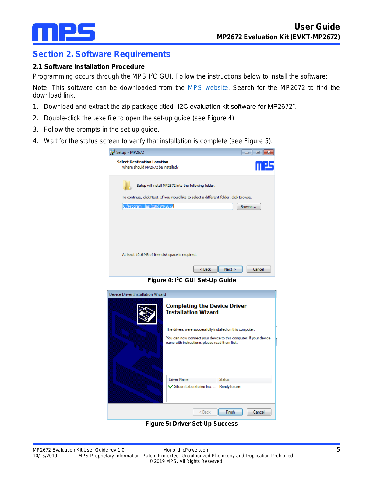
2.1 Software Installation Procedure....................................................................................................5
Section 3. Evaluation Kit Test Set-Up.................................................................................................. 66
3.1 Hardware Set-Up........................................................................................................................ 66
3.2 Powering Up the EVB................................................................................................................. 66
3.3 Software Set-Up........................................................................................................................... 6
3.4 Device Programming Instructions………………………………………………………………………...7
3.5 Troubleshooting Tips.................................................................................................................... 9
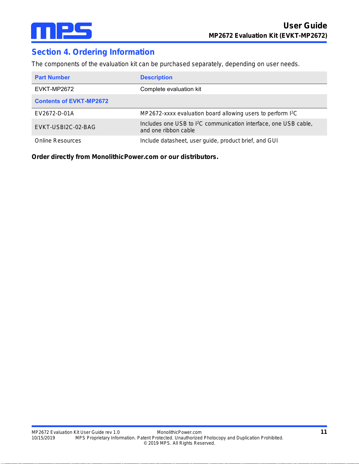
Section 4. Ordering Information........................................................................................................... 11

User Guide
MP2672 Evaluation Kit (EVKT-MP2672)
MP2672 Evaluation Kit User Guide rev 1.0 MonolithicPower.com 2
10/15/2019 MPS Proprietary Information. Patent Protected. Unauthorized Photocopy and Duplication Prohibited.
© 2019 MPS. All Rights Reserved.
Overview
Introduction
The EVKT-MP2672 is an evaluation kit for the MP2672. This board is designed for MP2672, which is
controlled by the GUI to enable the charging and discharging of the 2-cell battery. Its layout
accommodates most commonly used components. The default function of this board is preset for host-
mode and the battery regulation voltage is preset to 8.4V for the 2-cell Li-Ion battery.
Kit Contents
EVKT-MP2672 kit contents (items below can be ordered separately).
#
Part Number
Item
Quantity
1
EV2672-D-01A
MP2672 evaluation board
1
2
EVKT-USBI2C-02-
BAG
Includes one USB to I2C USB communication interface, one
USB cable, and one ribbon cable
1
Figure 1: EVKT-MP2672 Evaluation Kit Set-Up
USB to I2C
Dongle
USB Cable Ribbon Cable
Input Power
Supply
Load
GUI Battery

User Guide
MP2672 Evaluation Kit (EVKT-MP2672)
MP2672 Evaluation Kit User Guide rev 1.0 MonolithicPower.com 3
10/15/2019 MPS Proprietary Information. Patent Protected. Unauthorized Photocopy and Duplication Prohibited.
© 2019 MPS. All Rights Reserved.
Features and Benefits
4.5V to 6.0V Input Operation Voltage
Up to 2A Programmable Charge Current for Battery with 2 Cells in Series
Compatible with Host-Control and Standalone Mode
NVDC Power Path Management
Programmable Input Voltage Limit
Programmable Charge Voltage with 0.5% Accuracy
No External Sense Resistor Required
Integrated Cell Balancing Circuit for Cell Mismatch
Preconditioning for Fully Depleted Battery
Flexible New Charging Cycle Initiation
Charging Operation Indicator in Standalone Mode
Missing Battery Detection in Host-Control Mode
I2C Port for Flexible System Parameter Setting and Status Reporting in Host-Control Mode
Negative Temperature Coefficient Pin for Temperature Monitoring Compliant with JEITA
Built-in Charging Protection and Programmable Safety Timer
MOSFET Cycle-by-Cycle Over-Current Protection
Thermal Regulation and Thermal Shutdown
⚠️All changes made in I2C mode will NOT be retained once the EVB is powered down.
⚠️Information written in OTP mode CANNOT be changed.
Adjustable features:
I2C
OTP
Battery Regulation Voltage
Battery Pre-Charge Voltage
Cell Balance Start Threshold
Cell Voltage Mismatch Threshold
Fast Charge Current
Switching Frequency
Charge Timer
Battery Regulation Voltage
Battery Pre-Charge Voltage
Cell Balance Start Threshold
Cell Voltage Mismatch Threshold
Fast Charge Current
Switching Frequency
Auto-Recharge_EN
Balance_EOC_EN
Thermal Regulation Threshold
Kit Specifications
Feature
Specification
Supply for Board
4.5V to 6.0V
Operating Input Voltage
4.5V to 6.0V
Charge Capability
2A (max) / 8.4V (I2C)
System Load Capability
2.5A (max) / BATT + 300mV (I2C)
Operating Systems Supported
Windows XP, 7, and later
System Requirements
Minimum 22.2 MB free
GUI Software
MP2672 V1.0

User Guide
MP2672 Evaluation Kit (EVKT-MP2672)
MP2672 Evaluation Kit User Guide rev 1.0 MonolithicPower.com 4
10/15/2019 MPS Proprietary Information. Patent Protected. Unauthorized Photocopy and Duplication Prohibited.
© 2019 MPS. All Rights Reserved.
Section 1. Hardware Specifications
1.1 Personal Computer Requirements
The following minimal requirements must be met to use the EVKT-MP2672:
Operating System of Windows XP, 7 or later
Net Framework 4.0
PC with a minimum of one available USB port
At least 22.2 MB of free space
1.2 EV2672-D-01A Specifications
The EV2672-D-01A is an evaluation board for the MP2672. For more information, refer to the EV2672-
D-01A datasheet.
Figure 2: EV2672-D-01A Evaluation Board
1.3 EVKT-USBI2C-02 Specifications
EVKT-USBI2C-02 refers to the communication interface that connects the EVB, the PC, and its
supporting accessories. It provides I2C capabilities. Together with MPS Virtual Bench Pro and I2C GUI
tools, it provides a quick and easy way to evaluate the performance of MPS digital products. For more
details, refer to the EVKT-USBI2C-02 datasheet.
Figure 3: EVKT-USBI2C-02 Communication Interface
Feature
Specification
Supply for Evaluation
Board
4.5V to 6.0V
Operating Input Voltage
4.5V to 6.0V
Charge Capability
2A (max) / 8.4V (I2C)
System Load Capability
2.5A (max) / 6.7V (I2C)
EVB Size (L X W)
6.35cmx6.35cm

User Guide
MP2672 Evaluation Kit (EVKT-MP2672)
MP2672 Evaluation Kit User Guide rev 1.0 MonolithicPower.com 5
10/15/2019 MPS Proprietary Information. Patent Protected. Unauthorized Photocopy and Duplication Prohibited.
© 2019 MPS. All Rights Reserved.
Section 2. Software Requirements
2.1 Software Installation Procedure
Programming occurs through the MPS I2C GUI. Follow the instructions below to install the software:
Note: This software can be downloaded from the MPS website. Search for the MP2672 to find the
download link.
1. Download and extract the zip package titled “I2C evaluation kit software for MP2672”.
2. Double-click the .exe file to open the set-up guide (see Figure 4).
3. Follow the prompts in the set-up guide.
4. Wait for the status screen to verify that installation is complete (see Figure 5).
Figure 4: I2C GUI Set-Up Guide
Figure 5: Driver Set-Up Success

User Guide
MP2672 Evaluation Kit (EVKT-MP2672)
MP2672 Evaluation Kit User Guide rev 1.0 MonolithicPower.com 6
10/15/2019 MPS Proprietary Information. Patent Protected. Unauthorized Photocopy and Duplication Prohibited.
© 2019 MPS. All Rights Reserved.
Section 3. Evaluation Kit Test Set-up
3.1 Hardware Setup
The hardware must be properly configured prior to use. Follow the instructions below to set up the EVB:
1. Locate the proper wires to connect the EVB to the EVKT-USBI2C-02 communication interface.
2. Connect SCL, SDA, and GND (see Figure 6). Refer to the datasheet for further clarification.
Figure 6: EVB to MPS I2C Communication Interface Wire Connection
3.2 Powering up the EVB
1. Connect the positive and negative terminals of the load to the SYS and GND pins, respectively.
2. Connect the positive and negative terminals of the battery to the BATT and GND pins, respectively.
If it is a battery emulator, preset the battery voltage between 0V and 9.0V, then turn it off. Connect
the battery emulator output to the BATT and GND pins, respectively.
3. Preset the power supply output between 4.5V and 6.0V, then turn off the power supply. Connect the
positive and negative terminals of the power supply to the VIN and GND pins, respectively.
4. Make sure the battery voltage is present (if a battery emulator is used, turn on the battery emulator). Turn the
power supply on. The IC automatically powers up.
3.3 Software Set-Up
After connecting the hardware according to the steps above, follow the steps below to use the GUI
software:
1. Start the software. It will automatically check the EVB connection.
If the connection is successful, both the EVKT-USBI2C-02 and MP2672 Demo Board statuses
will show as "Connected" (see Figure 7).

User Guide
MP2672 Evaluation Kit (EVKT-MP2672)
MP2672 Evaluation Kit User Guide rev 1.0 MonolithicPower.com 7
10/15/2019 MPS Proprietary Information. Patent Protected. Unauthorized Photocopy and Duplication Prohibited.
© 2019 MPS. All Rights Reserved.
Figure 7: EVKT-USBI2C-02 and MP2672 Demo Board Show as Connected
If not, they will appear as “Not Connected”in red. Check the connections between the EVB,
communication interface, and PC. Re-plug the USB into the computer.
oMP2672 Demo Board “Not Connected”means that the evaluation board is not connected
correctly.
oUSB “Not Connected”means that the USB I2C communication interface is not connected
correctly.
2. Click the “Read All Registers” button to read the I2C register values. The default values are displayed
(see Figure 7).
3. Find the item to be changed and select the desired value from the drop-down menu.
4. Click the “Write All” button to update values. The changed information of the item will be downloaded
to the IC.
⚠️All changes made via the I2C will be restored to default values once the EVB is powered down.
3.4 Device Programming Instructions
The MP2672 is an OTP part. Follow the instructions outlined below to create and export customized
configurations:
1. Use a computer to open the MPS GUI software. Ensure the EVB is powered on.
2. Check the connection between the EVB and computer.
3. Select “OTP View” in the toolbar (see Figure 8).

User Guide
MP2672 Evaluation Kit (EVKT-MP2672)
MP2672 Evaluation Kit User Guide rev 1.0 MonolithicPower.com 8
10/15/2019 MPS Proprietary Information. Patent Protected. Unauthorized Photocopy and Duplication Prohibited.
© 2019 MPS. All Rights Reserved.
Figure 8: Select OTP
4. Enter a new table (see Figure 9). Any of the highlighted parameters can be changed.
Figure 9: Adjustable Parameters in OTP Mode
5. Select values from the drop-down menus. Be sure all the parameters are populated before exporting.
Export the configuration by clicking “Export” in the toolbar (see Figure 10).
Figure 10: Select “Export”

User Guide
MP2672 Evaluation Kit (EVKT-MP2672)
MP2672 Evaluation Kit User Guide rev 1.0 MonolithicPower.com 9
10/15/2019 MPS Proprietary Information. Patent Protected. Unauthorized Photocopy and Duplication Prohibited.
© 2019 MPS. All Rights Reserved.
6. Find a location for the exported file, and click “Save.” The customized configurations will be saved in
a .txt file (see Figure 11).
Figure 11: Exporting a File
7. Send this file to an MPS FAE to apply for the customized “xxxx”code.
3.5 Troubleshooting Tips
EVKT-USBI2C-02
If the USBI2C-02 driver is not properly installed, manual installation is required. Follow the steps below:
Note: Check the driver version. Find “USBXpress Device” in the Device Manager under USB controllers.
Right-click and view properties. Ensure the driver version matches the newest version. If the PC is
running Windows 10, Windows 10 may automatically install the older USB driver,which is not compatible.
The correct driver version is 4.0.0.0 (see Figure 12).
1. Install the correct USBXpress “.exe” file.
Choose either the 32-bit or 64-bit operating system.
32-bit: USBXpressInstaller_x86.exe
64-bit: USBXpressInstaller_x64.exe
2. Connect the EVKT-USBI2C-02 communication interface to the PC with the USB cable.

User Guide
MP2672 Evaluation Kit (EVKT-MP2672)
MP2672 Evaluation Kit User Guide rev 1.0 MonolithicPower.com 10
10/15/2019 MPS Proprietary Information. Patent Protected. Unauthorized Photocopy and Duplication Prohibited.
© 2019 MPS. All Rights Reserved.
Figure 12: Correct Driver Version is 4.0.0.0
No Supply
The IC’s input pin has an under-voltage lockout (UVLO) detection circuit. If the input voltage (VIN) is lower
than the UVLO rising threshold, the charging function is disabled.
No Charging Event
If the IC detects that the input voltage is below the UVLO falling threshold (enter no supply state) or over-
temperature protection is triggered (PWM converter enters shutdown state), the IC switches to charge-
suspend mode, and the system is powered by the battery.
Thermal Recovery
If the MP2672 (PWM converter) is in a shutdown state due to the die temperature exceeding the thermal
protection threshold, the IC powers on again once the die temperature decreases.

User Guide
MP2672 Evaluation Kit (EVKT-MP2672)
MP2672 Evaluation Kit User Guide rev 1.0 MonolithicPower.com 11
10/15/2019 MPS Proprietary Information. Patent Protected. Unauthorized Photocopy and Duplication Prohibited.
© 2019 MPS. All Rights Reserved.
Section 4. Ordering Information
The components of the evaluation kit can be purchased separately, depending on user needs.
Part Number
Description
EVKT-MP2672
Complete evaluation kit
Contents of EVKT-MP2672
EV2672-D-01A
MP2672-xxxx evaluation board allowing users to perform I2C
EVKT-USBI2C-02-BAG
Includes one USB to I2C communication interface, one USB cable,
and one ribbon cable
Online Resources
Include datasheet, user guide, product brief, and GUI
Order directly from MonolithicPower.com or our distributors.
This manual suits for next models
1
Table of contents
Other MPS Motherboard manuals

MPS
MPS EV1477-TF-00B User manual

MPS
MPS EV2633-R-01A User manual

MPS
MPS EV6001DN-00D User manual

MPS
MPS EV2759-Q-00A User manual

MPS
MPS EVHR2000-S-00A User manual

MPS
MPS EVKT6515 User manual

MPS
MPS EVBL2166-D-00A User manual

MPS
MPS MP2760 User manual

MPS
MPS EV6551-QB-00A User manual

MPS
MPS EV3209DJ-00A User manual

MPS
MPS EVKT-MP8833 User manual

MPS
MPS EV8042DF-00B User manual

MPS
MPS EV20045DQ-00A User manual

MPS
MPS EV2605DQ-00B User manual

MPS
MPS EV5920-5048-V-00A User manual

MPS
MPS MP2696A Reference guide

MPS
MPS EVKT-1203 User manual

MPS
MPS EVKT-MP8862 User manual

MPS
MPS EVmEZDPD3603A-00A User manual

MPS
MPS EV2483DQ-00C User manual