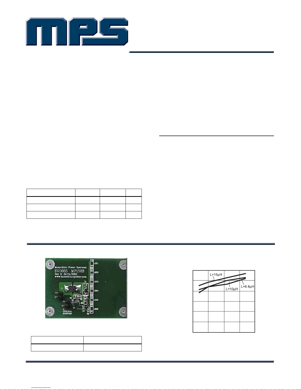
MPS EV0035 User manual


Other MPS Motherboard manuals

MPS
MPS EV6539B-F-00A User manual

MPS
MPS EVKT-MACOM User manual

MPS
MPS EV2602DQ-00B User manual

MPS
MPS MP2672 User manual

MPS
MPS MP5416 User manual

MPS
MPS EV2759-Q-00A User manual

MPS
MPS EV2483DQ-00C User manual

MPS
MPS EV6532-R-01A User manual

MPS
MPS EVQ4488-U-00B User manual

MPS
MPS EVHR2000-S-00A User manual

MPS
MPS EV2637A-R-00A User manual

MPS
MPS MagAlpha EVMA Q-00A Series Operating instructions

MPS
MPS EV7740DN-01B User manual

MPS
MPS EV3205DJ-00A Operating and maintenance instructions

MPS
MPS EV6536-U-00A User manual

MPS
MPS MP2760 User manual

MPS
MPS EV0035 User manual

MPS
MPS EV2696A-Q-00B User manual

MPS
MPS EV28163-Q-00A User manual

MPS
MPS mEZDPD4506A User manual


Popular Motherboard manuals by other brands


Analog Devices
Analog Devices EVAL-ADAU1777Z user guide

Texas Instruments
Texas Instruments DP83826EVM user guide

Biostar
Biostar M6VLB user manual

Texas Instruments
Texas Instruments bq25910EVM-854 user guide

Intel
Intel S5000XVN - Workstation Board Motherboard user guide

Asus
Asus EX-H610M-V3 D4 quick start guide


