MPS EV5920-5048-V-00A User manual

EV5920-5048-V-00A
60V, 15A, 7mΩ RDS(ON)
Hot-Swap Intelli-Fuse Solution
EV5920-5048-V-00A Rev. 1.0 MonolithicPower.com 1
5/14/2021 MPS Proprietary Information. Patent Protected. Unauthorized Photocopy and Duplication Prohibited.
© 2021 MPS. All Rights Reserved.
DESCRIPTION
The EV5920-5048-V-00A is an evaluation
board designed to demonstrate the capabilities
of the MP5920 and the MP5048.
The MP5920 is a hot-swap protection controller
that protects circuitry from transients on its input.
It works with an Intelli-Fuse, which can be
turned on or off via the ON pin and feeds back
the current, voltage, and temperature
information to the MP5920. The MP5920 limits
the Intelli-Fuse’s maximum load current by
controlling the current limit reference voltage
through CLPWM. The PMBus interface allows
the MP5920 to read current, voltage, or
temperature data and input power from a 12-bit
analog-to-digital converter (ADC).
The MP5920 is available in a TQFN-32
(4mmx4mm) package.
The MP5048 is a monolithic, integrated
controller and switch. It can operate as a
standalone device, or be controlled by a hot-
swap controller. The MP5048 is capable of
driving up to 15A of continuous current per
MP5048 device. The MP5048 simplifies system
design by providing an integrated solution to
monitor the output current and die temperature,
eliminating the need for an external current-
sense power resistor, power MOSFET, or
thermal sense. The MP5048 detects the power
FET gate, source, and drain short conditions,
and provides feedback for the controller. It can
also be paralleled for higher current
applications.
The MP5048 is available in a QFN-30
(5mmx5mm) package.
ELECTRICAL SPECIFICATIONS
Parameter Value Units
Input voltage 48 V
Output voltage 48 V
Current limit per MP5048 15 A
Number of active MP5920 devices 1 -
Number of active MP5048 devices 5 -
FEATURES
24V to 60V Operating Input Range
Maximum 15A Output Current per Phase
Integrated 7mΩ Power FET
Built-In MOSFET Driver
Integrated Current Sense with Sense
Output
Separate Current-Sense Output Used to
Configure the Over-Current Value
Built-In Soft Start and Insertion Delay
Output Short-Circuit Protection (SCP),
Over-Temperature Protection (OTP), and
Built-In Fuse Health Diagnostics
Fault Signal Output
Parallel Operation for Higher Current
Applications
Integrated Intelli-Fuse Temperature Sense
Controllable Intelli-Fuse On/Off
PMBus Fast Mode Compliant
Built-In 12-Bit ADC for Current, VIN, VOUT, or
Temperature Reading
Programmable Current Limit Reference
Voltage for Intelli-Fuse Current Limit Set
Parameters Configurable via the PMBus
Reports Power and Energy Consumption
APPLICATIONS
Hot-Swap Applications
PC Cards
Disk Drives
Servers
Networking
Laptops
A
ll MPS parts are lead-free, halogen-free, and adhere to the RoHS
directive. For MPS green status, please visit the MPS website unde
r
Quality Assurance. “MPS”, the MPS logo, and “Simple, Easy Solutions” are
registered trademarks of Monolithic Power Systems, Inc. or its subsidiaries.

EV5920-5048-V-00A, 60V, 15A, 7mΩ RDS(ON) HOT-SWAP INTELLI-FUSE SOLUTION
EV5920-5048-V-00A Rev. 1.0 MonolithicPower.com 2
5/14/2021 MPS Proprietary Information. Patent Protected. Unauthorized Photocopy and Duplication Prohibited.
© 2021 MPS. All Rights Reserved.
EV5920-5048-V-00A EVALUATION BOARD
(LxWxH) 10cmx15cmx1.3cm
Board Number MPS IC Numbers
EV5920-5048-V-00A MP5920GRT-0000,
MP5048GU

EV5920-5048-V-00A, 60V, 15A, 7mΩ RDS(ON) HOT-SWAP INTELLI-FUSE SOLUTION
EV5920-5048-V-00A Rev. 1.0 MonolithicPower.com 3
5/14/2021 MPS Proprietary Information. Patent Protected. Unauthorized Photocopy and Duplication Prohibited.
© 2021 MPS. All Rights Reserved.
QUICK START GUIDE
1. Attach the load terminals to:
a. Positive (+): VOUT
b. Negative (-): GND
2. Preset the power supply output to 48V, then turn off the power supply.
3. Attach the power supply terminals to:
a. Positive (+): VIN
b. Negative (-): GND
4. Ensure that the EN switch (S1) is on; this switch turns on the MP5920.
5. Turn on the VIN power supply. The board should start up automatically.
EV5920-5048-V00A DEFAULT SETTINGS
Parameter Value Unit Notes
VIN OVP limit 58.185 V VIN_OV_FAULT_LIMIT (55h)
VIN On threshold 39.21 V VIN_ON (35h)
VIN Off threshold 37.15 V VIN_OFF (36h)
PG On threshold 35.94 V POWER_GOOD_ON (5Eh)
PG Off threshold 27.72 V POWER_GOOD_OFF (5Fh)
OCP total limit 96.41 A IOUT_OC_FAULT_LIMIT(46h)
OCP limit (per MP5048) 17.2 A RCS and RCLREF
OC warning limit 88.987 A IIN_OC_WARN_LIMIT (5Dh)
Soft-start time 24 ms CSS
OTP limit 120 °C OT_FAULT_LIMIT (4Fh)
OT warning limit 110 °C OT_WARN_LIMIT (51h)
PROGRAMMING USER GUIDE
1. Use the PMBus interface kit (EVKT-USBI2C-02) to connect the EV5920-5048-V-00A to a PC (see
Figure 1).
USB Cable
Programmable Kit
with PMBus Interface
Ribbon Cable
EV5920-5048-V-
00A
Load
Input Power
Supply
GUI
Figure 1: PMBus Connection Diagram
2. Turn on the power supply.
3. Open the GUI, then click the “Scan” button (see Figure 2). The devices should be listed in the left
column.

EV5920-5048-V-00A, 60V, 15A, 7mΩ RDS(ON) HOT-SWAP INTELLI-FUSE SOLUTION
EV5920-5048-V-00A Rev. 1.0 MonolithicPower.com 4
5/14/2021 MPS Proprietary Information. Patent Protected. Unauthorized Photocopy and Duplication Prohibited.
© 2021 MPS. All Rights Reserved.
Figure 2: MP5920 Scan Operation
4. Select the device labeled “MP5920 [40]”.
5. Update the parameters in the “Input” page following the sequence below:
a. E-Fuse Part Number: Select “MP5048.”
b. Sense Voltage Set: Set RUP to 162kΩ and RDOWN to 10kΩ.
c. Current Monitor Gain: Set to 25μA/A.
d. Average RIMON: Depending on the average resistor for the IMON pin, set to 0.72kΩ (3.6kΩ / 5
phases in parallel).
e. Click “Update.”
Figure 3: GUI Input Page
6. At this point, the system’s operation status can be monitored via the “Monitor” page (see Figure 4)
Figure 4: GUI Monitor Page

EV5920-5048-V-00A, 60V, 15A, 7mΩ RDS(ON) HOT-SWAP INTELLI-FUSE SOLUTION
EV5920-5048-V-00A Rev. 1.0 MonolithicPower.com 5
5/14/2021 MPS Proprietary Information. Patent Protected. Unauthorized Photocopy and Duplication Prohibited.
© 2021 MPS. All Rights Reserved.
7. Use the “Protection” page configures the protection parameters, include the over-voltage (OV),
over-current (OC), over-power (OP), over-temperature (OT), power good (PG) threshold, and
packet error checking (PEC) mode settings.
Figure 5: GUI Protection Page
8. Some advanced functions can be configured in the “Advanced” page.
a. Basic Configuration: Set the VIN on/off threshold, tON delay time, sample average time, and
address selection (see Figure 6).
Figure 6: GUI Advanced Page, Basic Configuration Tab
b. CLREF: To use the MP5920 to provide the CLREF voltage, remove all MP5048 CLREF
resistors, including R1, R4, R74, R78, and R82.
c. GPIO: GPIO can be configured to indicate a programmed fault or alert to the system.
Figure 7: GUI Advanced Page, GPIO Tab

EV5920-5048-V-00A, 60V, 15A, 7mΩ RDS(ON) HOT-SWAP INTELLI-FUSE SOLUTION
EV5920-5048-V-00A Rev. 1.0 MonolithicPower.com 6
5/14/2021 MPS Proprietary Information. Patent Protected. Unauthorized Photocopy and Duplication Prohibited.
© 2021 MPS. All Rights Reserved.
d. BB Configuration/BB Read/User Data: For details on configuring these functions, refer to the
MP5920 datasheet.
9. The register list menu allows the user to import, export, and diagnose possible issues with the
configuration file. Once the device is selected from the device list, all of the device registers in the
register map are read and listed in the table (in hexadecimal format). The user also can enter the
register’s read/write interface by clicking “ALT” + “W”.
Figure 8: GUI Register Page
EV5920-5048-V-00A, 60V, 15A, 7mΩ RDS(ON) HOT-SWAP INTELLI-FUSE SOLUTION
EV5920-5048-V-00A Rev. 1.0 MonolithicPower.com 7
5/14/2021 MPS Proprietary Information. Patent Protected. Unauthorized Photocopy and Duplication Prohibited.
© 2021 MPS. All Rights Reserved.
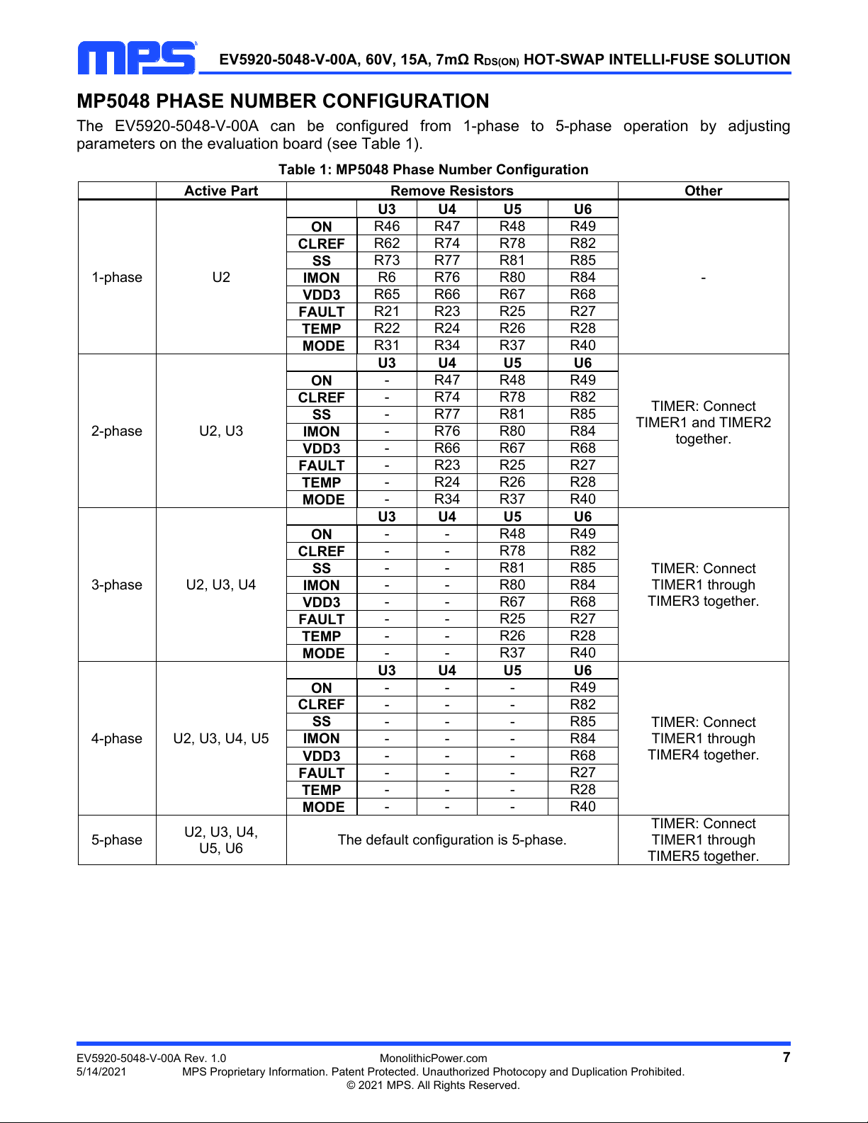
MP5048 PHASE NUMBER CONFIGURATION
The EV5920-5048-V-00A can be configured from 1-phase to 5-phase operation by adjusting
parameters on the evaluation board (see Table 1).
Table 1: MP5048 Phase Number Configuration
Active Part Remove Resistors Other
1-phase U2
U3 U4 U5 U6
-
ON R46 R47 R48 R49
CLREF R62 R74 R78 R82
SS R73 R77 R81 R85
IMON R6 R76 R80 R84
VDD3 R65 R66 R67 R68
FAULT R21 R23 R25 R27
TEMP R22 R24 R26 R28
MODE R31 R34 R37 R40
2-phase U2, U3
U3 U4 U5 U6
TIMER: Connect
TIMER1 and TIMER2
together.
ON - R47 R48 R49
CLREF - R74 R78 R82
SS - R77 R81 R85
IMON - R76 R80 R84
VDD3 - R66 R67 R68
FAULT - R23 R25 R27
TEMP - R24 R26 R28
MODE - R34 R37 R40
3-phase U2, U3, U4
U3 U4 U5 U6
TIMER: Connect
TIMER1 through
TIMER3 together.
ON - - R48 R49
CLREF - - R78 R82
SS - - R81 R85
IMON - - R80 R84
VDD3 - - R67 R68
FAULT - - R25 R27
TEMP - - R26 R28
MODE - - R37 R40
4-phase U2, U3, U4, U5
U3 U4 U5 U6
TIMER: Connect
TIMER1 through
TIMER4 together.
ON - - - R49
CLREF - - - R82
SS - - - R85
IMON - - - R84
VDD3 - - - R68
FAULT - - - R27
TEMP - - - R28
MODE - - - R40
5-phase U2, U3, U4,
U5, U6 The default configuration is 5-phase.
TIMER: Connect
TIMER1 through
TIMER5 together.

EV5920-5048-V-00A, 60V, 15A, 7mΩ RDS(ON) HOT-SWAP INTELLI-FUSE SOLUTION
EV5920-5048-V-00A Rev. 1.0 MonolithicPower.com 8
5/14/2021 MPS Proprietary Information. Patent Protected. Unauthorized Photocopy and Duplication Prohibited.
© 2021 MPS. All Rights Reserved.
EVALUATION BOARD SCHEMATIC
3.3V_EXT
C34
1µF
R61
2kΩ
R60
2kΩ
SDA
SCL F
P5
2
4
6
8
10
1
3
5
7
9
1
3
5
7
9
2
4
6
8
10
PMBus
F
VCC
R56
NS
ADDR
R61
0Ω
C33
10nF
F
VCC
VCC
C28
4.7µF
C27
100nF
F
R55
100kΩ
R59
100kΩ
PG
GPIO 1
VINSEN
VOSEN
IMO N
TEMP
R63
10kΩ
C35
1nF
F
LDO
C31
4.7µF
MP5920
VINSEN
VOSEN
DNC1
IMO N
DNC2
TEMP
DNC3
LDO1
F
U1
1
2
3
4
5
6
7
8
GND 3
GND 2
VCC2
ADDR
GPIO
DNC10
DNC9
DNC8
33
32
31
30
29
28
26
27
25
24
23
22
21
20
19
18
17
SDA
SCL
ALERT#
DNC7
DNC6
DNC5
DNC4
EN
SDA
SCL
ALERT#
GPIO 2
GPIO 3
D_OC
VCC
R58
10kΩ
R88
100kΩ
R89
100kΩ
LDO2
VCC1
GND 1
RESET_N
CLREF
GO K
ON
EN
PG
9
10
11
12
13
14
16
15
LDO
VCC
CLPWM
GO K
ON _C ONT RO L
S1
R18
100kΩ
C31
4.7µF C29
1µF
R87
0Ω
PGND AGND F
VCC F
R45
4.7kΩ
C29
10nF
F
EN1_SW
R19
100Ω
F
2
1
3
2
1
3
VIN VINSEN
F
R41
162kΩ R42
10kΩ
C25
10nF
VOUT VOSEN
F
R44
162kΩ R43
10kΩ
C26
10nF
IM O N C36
100nF
F
3.3V_EXT
R71
NS
VCC
ON _C ONTR O L R51
10kΩ
ON
R90
10kΩ
R62
NS
VCC
F
VCC
R52
10kΩ
GO K R54
0Ω
FAULT
R53
10kΩ
D_OC
CLREF
C47
10nF
R86
4.7kΩ
CLPWM
F
Figure 9: Evaluation Board Schematic (MP5920 Portion)

EV5920-5048-V-00A, 60V, 15A, 7mΩ RDS(ON) HOT-SWAP INTELLI-FUSE SOLUTION
EV5920-5048-V-00A Rev. 1.0 MonolithicPower.com 9
5/14/2021 MPS Proprietary Information. Patent Protected. Unauthorized Photocopy and Duplication Prohibited.
© 2021 MPS. All Rights Reserved.
EVALUATION BOARD SCHEMATIC (continued)
VIN
GND
VIN
PGND
D1
12
5.0SMDJ51A
C1
C2012X7S2A474K125AE
3.3V_EXT ON 1
R50
0Ω
CLREF
R1
62kΩ
R2
3.6kΩ
CS1
IMO N
TIMER1
R3
3.6kΩ C3
10nF
F
SS
R72
0Ω
C4
100nF
F
FAULT
TEMP
R16
0Ω R17
0Ω
MODE1 MODE
R20
0Ω
MP5048
U2
C1
2.2µF
C2
2.2µF
R64
0Ω
VCC
F
VOUT
GND
C24
C2012X7S2A47
4K125AE
B380-13-F
+ PC1
100µF
+ PC2
NS
VOUT
VIN1
VIN2
VIN3
GND
CS
IMO N
TIMER
SS
VCC
3V
VTEMP
FAULT
MODE
VOUT1
VOUT2
VOUT3
VOUT4
VOUT5
VOUT6
VOUT7
VOUT8
VOUT9
VOUT10
VOUT11
VOUT12
VOUT13
VOUT14
VOUT15
CLREF
ON
1
2
18
26
24
19
20
23
22
29
30
21
3
4
5
6
7
8
9
10
11
12
13
14
16
15
17
28
25
27
C37
NS
ON ON2
R46
0Ω
CLREF
R4
62kΩ
R5
3.6kΩ
CS2
IMO N
TIMER2
R6
3.6kΩ C5
10nF
F
SS
R73
0Ω
C6
100nF
F
FAULT
TEMP
R21
0Ω R22
0Ω
MODE2 MODE
R31
0Ω
MP5048
U3
C13
2.2µF
C14
2.2µF
R65
0Ω
VCC
VIN1
VIN2
VIN3
GND
CS
IMO N
TIMER
SS
VCC
3V
VTEMP
FAULT
MODE
VOUT1
VOUT2
VOUT3
VOUT4
VOUT5
VOUT6
VOUT7
VOUT8
VOUT9
VOUT10
VOUT11
VOUT12
VOUT13
VOUT14
VOUT15
CLREF
ON
1
2
18
26
24
19
20
23
22
29
30
21
3
4
5
6
7
8
9
10
11
12
13
14
16
15
17
28
25
27
VIN
SS1
SS2
VOUT
F
C38
NS
ON ON3
R47
0Ω
CLREF
R74
62kΩ
R75
3.6kΩ
CS3
IMO N
TIMER3
R76
3.6kΩ C39
10nF
F
SS
R77
0Ω
C40
100nF
F
FAULT
TEMP
R23
0Ω R24
0Ω
MODE3 MODE
R34
0Ω
MP5048
U4
C15
2.2µF
C16
2.2µF
R66
0Ω
VCC
VIN1
VIN2
VIN3
GND
CS
IMO N
TIMER
SS
VCC
3V
VTEMP
FAULT
MODE
VOUT1
VOUT2
VOUT3
VOUT4
VOUT5
VOUT6
VOUT7
VOUT8
VOUT9
VOUT10
VOUT11
VOUT12
VOUT13
VOUT14
VOUT15
CLREF
ON
1
2
18
26
24
19
20
23
22
29
30
21
3
4
5
6
7
8
9
10
11
12
13
14
16
15
17
28
25
27
VIN
SS3
VOUT
F
C45
NS
ON ON4
R48
0Ω
CLREF
R78
62kΩ
R79
3.6kΩ
CS3
IMO N
TIMER3
R80
3.6kΩ C41
10nF
F
SS
R81
0Ω
C42
100nF
F
FAULT
TEMP
R25
0Ω R26
0Ω
MODE4 MODE
R37
0Ω
MP5048
U5
C17
1µF
C18
4.7µF
R67
0Ω
VCC
VIN1
VIN2
VIN3
GND
CS
IMO N
TIMER
SS
VCC
3V
VTEMP
FAULT
MODE
VOUT1
VOUT2
VOUT3
VOUT4
VOUT5
VOUT6
VOUT7
VOUT8
VOUT9
VOUT10
VOUT11
VOUT12
VOUT13
VOUT14
VOUT15
CLREF
ON
1
2
18
26
24
19
20
23
22
29
30
21
3
4
5
6
7
8
9
10
11
12
13
14
16
15
17
28
25
27
VIN
SS3
VOUT
F
C46
NS
ON ON5
R49
0Ω
CLREF
R82
62kΩ
R83
3.6kΩ
CS3
IMO N
TIMER3
R84
3.6kΩ C43
10nF
F
SS
R85
0Ω
C44
100nF
F
FAULT
TEMP
R27
0Ω R28
0Ω
MODE5 MODE
R40
0Ω
MP5048
U6
C19
1µF
C20
4.7µF
R68
0Ω
VCC
VIN1
VIN2
VIN3
GND
CS
IMO N
TIMER
SS
VCC
3V
VTEMP
FAULT
MODE
VOUT1
VOUT2
VOUT3
VOUT4
VOUT5
VOUT6
VOUT7
VOUT8
VOUT9
VOUT10
VOUT11
VOUT12
VOUT13
VOUT14
VOUT15
CLREF
ON
1
2
18
26
24
19
20
23
22
29
30
21
3
4
5
6
7
8
9
10
11
12
13
14
16
15
17
28
25
27
VIN
SS3
VOUT
F
P1
P2
SDA
SCL
ALERT
D_OC
MODE
VCC
MODE
F
SDA
SCL
ALERT#
D_OC
CS1
CS2
CS3
CS4
CS5
TEMP
CS1
CS2
CS3
CS4
CS5
TEMP
1
1
1
1
1
1
1
2
1
1
1
1
1
2
1
1
1
1
1
1
VOSEN
VINSEN
SS
IMO N
CLREF
FAULT
VOSEN
VINSEN
SS
IMO N
CLREF
FAULT
1
1
1
1
1
1
TIMER1
TIMER2
TIMER3
TIMER4
TIMER5
EN
TIMER1
TIMER2
TIMER3
TIMER4
TIMER5
EN
1
1
1
1
1
1
AGND-1
AGND-2
AGND-3
GP IO 1
GP IO 2
GP IO 3
AGND
AGND
AGND
GP IO 1
GP IO 2
GP IO 3
1
1
1
1
1
VCC
3.3V_EXT
CLPWM
ON
PG
VCC
3.3V_EXT
CLPWM
ON
PG
VOUT1-1
1
2
3
4
1
2
3
4VOUT
4P
VOUT1-2
1
2
3
4
1
2
3
4VOUT
4P
VOUT1-3
1
2
3
4
1
2
3
4VOUT
4P
VOUT1-4
1
2
3
4
1
2
3
4VOUT
4P
VIN-1
1
2
3
4
1
2
3
4VIN
4P
VIN-2
1
2
3
4
1
2
3
4VIN
4P
VIN-3
1
2
3
4
1
2
3
4VIN
4P
VIN-4
1
2
3
4
1
2
3
4VIN
4P
PGND-1
1
2
3
4
1
2
3
4PGND
4P
PGND-2
1
2
3
4
1
2
3
4PGND
4P
PGND-3
1
2
3
4
1
2
3
4PGND
4P
PGND-4
1
2
3
4
1
2
3
4PGND
4P
Figure 10: Evaluation Board Schematic (MP5048 Portion)
EV5920-5048-V-00A, 60V, 15A, 7mΩ RDS(ON) HOT-SWAP INTELLI-FUSE SOLUTION
EV5920-5048-V-00A Rev. 1.0 MonolithicPower.com 10
5/14/2021 MPS Proprietary Information. Patent Protected. Unauthorized Photocopy and Duplication Prohibited.
© 2021 MPS. All Rights Reserved.
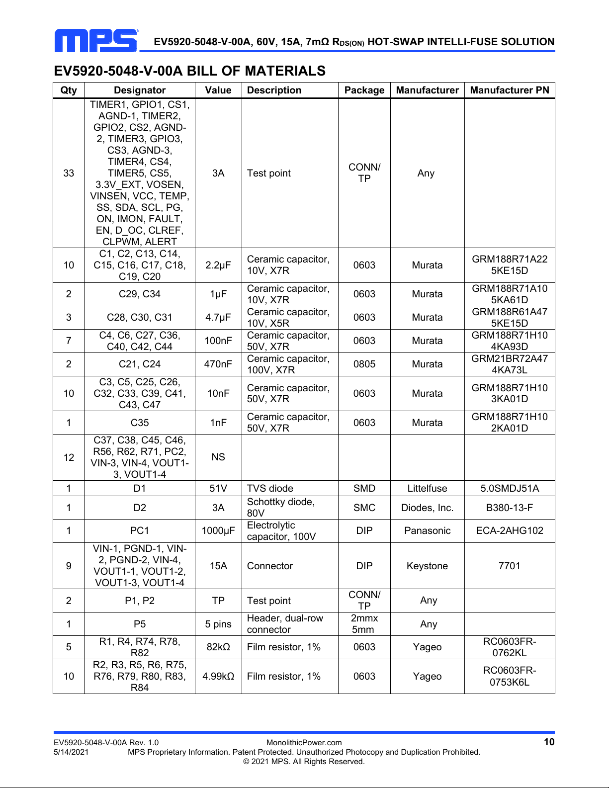
EV5920-5048-V-00A BILL OF MATERIALS
Qty Designator Value Description Package Manufacturer Manufacturer PN
33
TIMER1, GPIO1, CS1,
AGND-1, TIMER2,
GPIO2, CS2, AGND-
2, TIMER3, GPIO3,
CS3, AGND-3,
TIMER4, CS4,
TIMER5, CS5,
3.3V_EXT, VOSEN,
VINSEN, VCC, TEMP,
SS, SDA, SCL, PG,
ON, IMON, FAULT,
EN, D_OC, CLREF,
CLPWM, ALERT
3A Test point CONN/
TP Any
10
C1, C2, C13, C14,
C15, C16, C17, C18,
C19, C20
2.2μF Ceramic capacitor,
10V, X7R 0603 Murata GRM188R71A22
5KE15D
2 C29, C34 1μF Ceramic capacitor,
10V, X7R 0603 Murata GRM188R71A10
5KA61D
3 C28, C30, C31 4.7μF Ceramic capacitor,
10V, X5R 0603 Murata GRM188R61A47
5KE15D
7 C4, C6, C27, C36,
C40, C42, C44 100nF Ceramic capacitor,
50V, X7R 0603 Murata GRM188R71H10
4KA93D
2 C21, C24 470nF Ceramic capacitor,
100V, X7R 0805 Murata GRM21BR72A47
4KA73L
10
C3, C5, C25, C26,
C32, C33, C39, C41,
C43, C47
10nF Ceramic capacitor,
50V, X7R 0603 Murata GRM188R71H10
3KA01D
1 C35 1nF Ceramic capacitor,
50V, X7R 0603 Murata GRM188R71H10
2KA01D
12
C37, C38, C45, C46,
R56, R62, R71, PC2,
VIN-3, VIN-4, VOUT1-
3, VOUT1-4
NS
1 D1 51V TVS diode SMD Littelfuse 5.0SMDJ51A
1 D2 3A Schottky diode,
80V SMC Diodes, Inc. B380-13-F
1 PC1 1000μF Electrolytic
capacitor, 100V DIP Panasonic ECA-2AHG102
9
VIN-1, PGND-1, VIN-
2, PGND-2, VIN-4,
VOUT1-1, VOUT1-2,
VOUT1-3, VOUT1-4
15A Connector DIP Keystone 7701
2 P1, P2 TP Test point CONN/
TP Any
1 P5 5 pins Header, dual-row
connector
2mmx
5mm Any
5 R1, R4, R74, R78,
R82 82kΩ Film resistor, 1% 0603 Yageo RC0603FR-
0762KL
10
R2, R3, R5, R6, R75,
R76, R79, R80, R83,
R84
4.99kΩ Film resistor, 1% 0603 Yageo RC0603FR-
0753K6L
EV5920-5048-V-00A, 60V, 15A, 7mΩ RDS(ON) HOT-SWAP INTELLI-FUSE SOLUTION
EV5920-5048-V-00A Rev. 1.0 MonolithicPower.com 11
5/14/2021 MPS Proprietary Information. Patent Protected. Unauthorized Photocopy and Duplication Prohibited.
© 2021 MPS. All Rights Reserved.
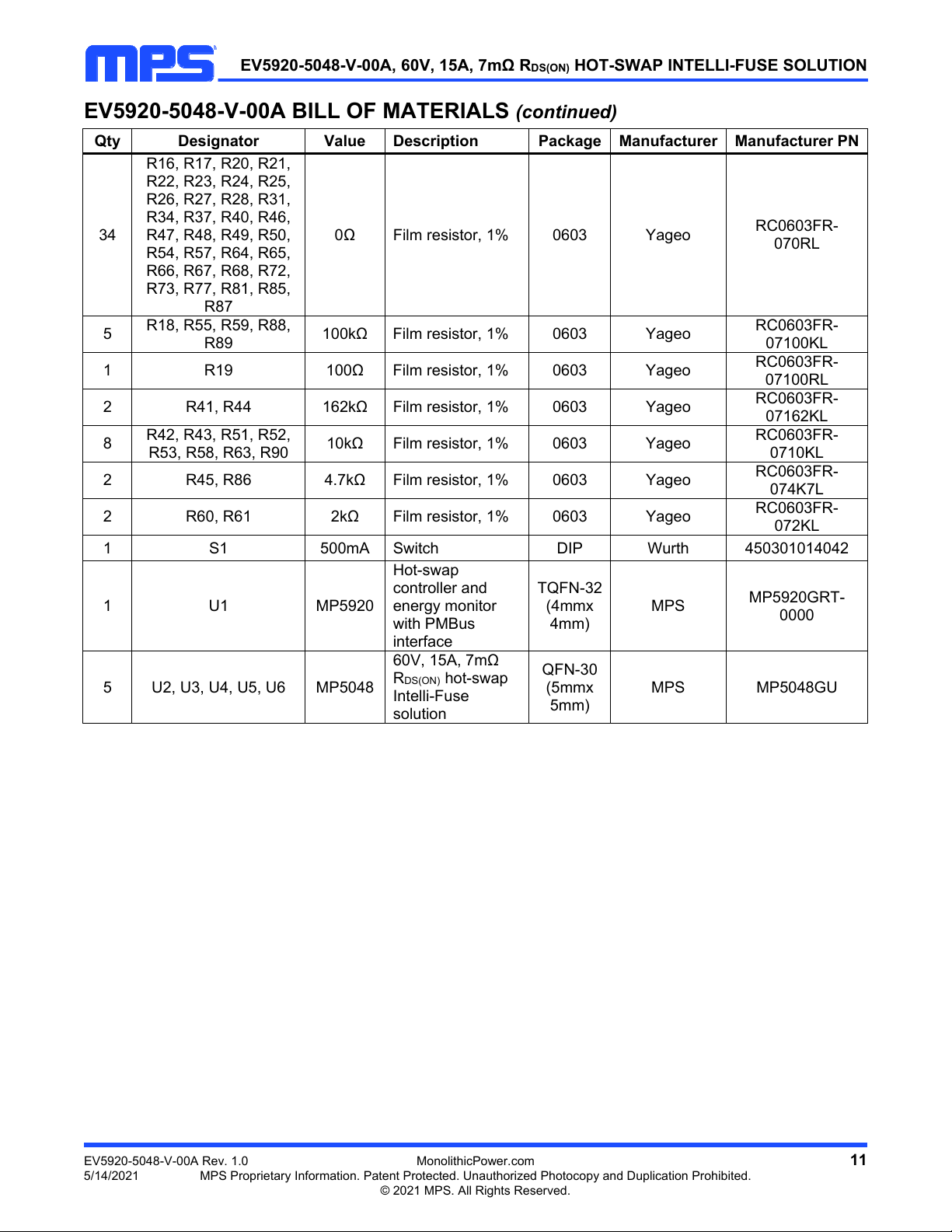
EV5920-5048-V-00A BILL OF MATERIALS (continued)
Qty Designator Value Description Package Manufacturer Manufacturer PN
34
R16, R17, R20, R21,
R22, R23, R24, R25,
R26, R27, R28, R31,
R34, R37, R40, R46,
R47, R48, R49, R50,
R54, R57, R64, R65,
R66, R67, R68, R72,
R73, R77, R81, R85,
R87
0Ω Film resistor, 1% 0603 Yageo RC0603FR-
070RL
5 R18, R55, R59, R88,
R89 100kΩ Film resistor, 1% 0603 Yageo RC0603FR-
07100KL
1 R19 100Ω Film resistor, 1% 0603 Yageo RC0603FR-
07100RL
2 R41, R44 162kΩ Film resistor, 1% 0603 Yageo RC0603FR-
07162KL
8 R42, R43, R51, R52,
R53, R58, R63, R90 10kΩ Film resistor, 1% 0603 Yageo RC0603FR-
0710KL
2 R45, R86 4.7kΩ Film resistor, 1% 0603 Yageo RC0603FR-
074K7L
2 R60, R61 2kΩ Film resistor, 1% 0603 Yageo RC0603FR-
072KL
1 S1 500mA Switch DIP Wurth 450301014042
1 U1 MP5920
Hot-swap
controller and
energy monitor
with PMBus
interface
TQFN-32
(4mmx
4mm)
MPS MP5920GRT-
0000
5 U2, U3, U4, U5, U6 MP5048
60V, 15A, 7mΩ
RDS(ON) hot-swap
Intelli-Fuse
solution
QFN-30
(5mmx
5mm)
MPS MP5048GU

EV5920-5048-V-00A, 60V, 15A, 7mΩ RDS(ON) HOT-SWAP INTELLI-FUSE SOLUTION
EV5920-5048-V-00A Rev. 1.0 MonolithicPower.com 12
5/14/2021 MPS Proprietary Information. Patent Protected. Unauthorized Photocopy and Duplication Prohibited.
© 2021 MPS. All Rights Reserved.
PCB LAYOUT
Figure 11: Top Layer Figure 12: Mid-Layer 1
EV5920-5048-V-00A, 60V, 15A, 7mΩ RDS(ON) HOT-SWAP INTELLI-FUSE SOLUTION
EV5920-5048-V-00A Rev. 1.0 MonolithicPower.com 13
5/14/2021 MPS Proprietary Information. Patent Protected. Unauthorized Photocopy and Duplication Prohibited.© 2021 MPS. All Rights Reserved.
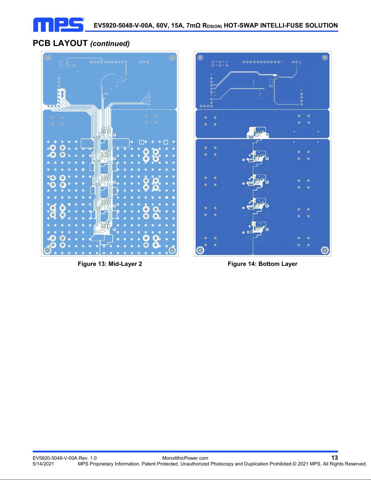
PCB LAYOUT (continued)
Figure 13: Mid-Layer 2 Figure 14: Bottom Layer
EV5920-5048-V-00A, 60V, 15A, 7mΩ RDS(ON) HOT-SWAP INTELLI-FUSE SOLUTION
Notice: The information in this document is subject to change without notice. Please contact MPS for current specifications.
Users should warrant and guarantee that third-party Intellectual Property rights are not infringed upon when integrating MPS
products into any application. MPS will not assume any legal responsibility for any said applications.
EV5920-5048-V-00A Rev. 1.0 MonolithicPower.com 14
5/14/2021 MPS Proprietary Information. Patent Protected. Unauthorized Photocopy and Duplication Prohibited.
© 2021 MPS. All Rights Reserved.
REVISION HISTORY
Revision # Revision Date Description Pages Updated
1.0 5/14/2021 Initial Release -
Table of contents
Other MPS Motherboard manuals

MPS
MPS EV6001DN-00D User manual

MPS
MPS EV6532-R-01A User manual

MPS
MPS EV3209DJ-00A User manual

MPS
MPS EV2605DQ-00B User manual

MPS
MPS EV6539B-F-00A User manual

MPS
MPS EVKT-MP8862 User manual

MPS
MPS EV7740DN-01B User manual

MPS
MPS EV2633-R-01A User manual

MPS
MPS MP2672 User manual

MPS
MPS EV2637A-R-00A User manual

MPS
MPS MP5416 User manual

MPS
MPS EV8042DF-00B User manual

MPS
MPS EVKT-MP8860 User manual

MPS
MPS EVQ6541A-QK-00A User manual

MPS
MPS mEZDPD4506A User manual

MPS
MPS EV3205DJ-00A Operating and maintenance instructions

MPS
MPS EV2483DQ-00C User manual

MPS
MPS EV0035 User manual

MPS
MPS EV6536-U-00A User manual

MPS
MPS EV26059DQ-00B User manual


