AZZA P4 Series User manual

The P4 Mainboard Series Page 1
P4 Mainboard
P4 MainboardP4 Mainboard
P4 Mainboard
S
SS
Se
ee
eries Manual
ries Manualries Manual
ries Manual
SOCKET 478 SDR M-ATX Mainboard
P4MAS
P4MASP4MAS
P4MAS-
--
-MNB
MNBMNB
MNB
P4M2S
P4M2SP4M2S
P4M2S-
--
-MVB
MVBMVB
MVB
P4XES
P4XESP4XES
P4XES-
--
-MVB
MVBMVB
MVB
Version 1.x
UM-P4M2AXES-MNVB-E2
Rev 1.0V
Creation Date: : 17 January 2003

The P4 Mainboard Series
Page 2
Copyright
This publication contains information that is protected by copyright. No part of
it may be reproduced in any form or by any means or used to make any trans-
formation adaptation without prior written permission from the copyright hold-
ers. This publication is provided for informational purposes only. The manufac-
turer makes no representations or warranties with respect to the contents or
use of this manual and specifically disclaims any express or implied warranties
of merchantability or fitness for any particular purpose. The user will assume
the entire risk of the use or the results of the use of this document. The manu-
facturer reserves the right to revise this publication and make changes to its
contents at any time, without prior notice.
2002. All Rights Reserved.
Trademarks
Microsoft®, MS-DOS®, Windows®95 and Windows®98 are registered trade-
marks of Microsoft Corporation. Intel®PentiumTM 4 is a registered trademark of
Intel Corporation. Phoenix Award is the registered trademark of Phoenix Award
Software, Inc. Other trademarks and registered trademarks of products ap-
pearing in this publication are the properties of their respective holders.
Package Checklist
This package contains the following items:
!Mainboard
!Users manual
!One IDE cable
!One 34-pin floppy disk drive cable
!One Driver Utility CD
If any of these items are damaged or missing, please contact your dealer or
sales representative for assistance.
Technical Support
If you require additional information or assistance during installation please
contact your dealer. Your dealer will be able to provide the latest information.
User’s Notice

The P4 Mainboard Series Page 3
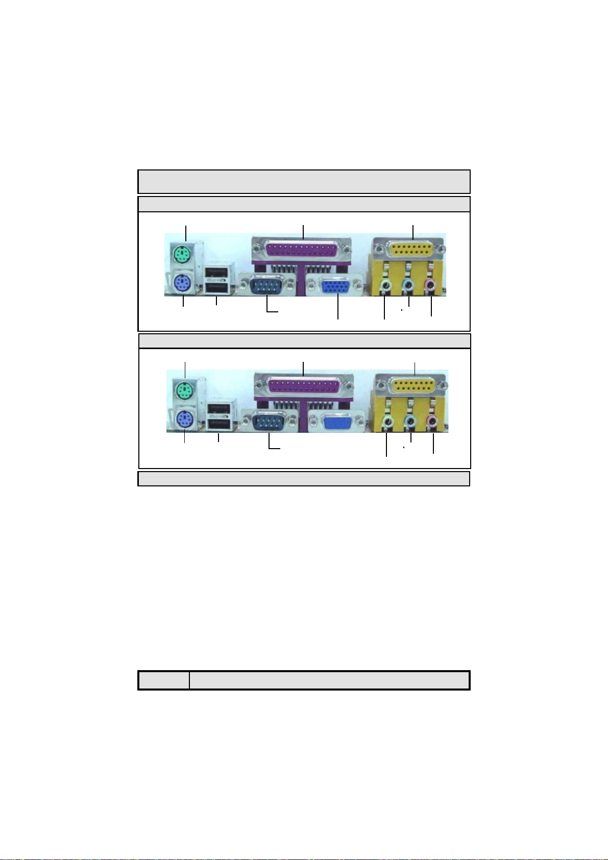
!"# $
%&'!
!"!#
$ #
%('')
(''*' +
(''"
,-%./"'
$%&"
!'
&$
()
('
*++!,-*.
!/!$&/
&"&*&/0
(1'++!&/ 0
0&('$('2!3$&/
45&/
"6"6&/
7*('&/
%'0.1 2
048595%%2'+/&/7
0&/7
0$&/7
0:6'&/7
"*.1
+,&/#
*#
Table Of Contents

The P4 Mainboard Series
Page 4
$./'
9;!&/#
9'&/ #
-&5.&/#
&/<
0"6"6&/<
=)(&/<
('9)&/ <
23%")
7>8;!
7>8&"*6
7>8"6"6
7>8&&5!
/40(",'
"
40(!
4"!
()"'
$ )%"
256(#)
&' +
+!768')'
!'9#1#'6"%:1#'
*3%%'
5+?%'
",
'+
"
;./"6./<)
@2'+
24'
Table Of Contents

The P4 Mainboard Series Page 5
Introduction
!
!"
!
!"
#!"
$
%
#
#$ #%&
! ! ! ' ()
%
!&'(!
)
*
!
!"
!
!"
#!"
$
%
#
#$ #%&
! ! ! ' ()
%
!&'(!
)
*
)
*

The P4 Mainboard Series
Page 6
1.2.1. The P4 Mainboard Series
The mainboards in the P4 series are Pentium™ 4 SDRAM platforms. They
come with two onboard SDRAM DIMM slots that are able to support a maxi-
mum memory of 1GB. They also come with 3 PCI slots and 1 AGP (Accelerated
Graphics Port) slot. They all come with Onboard Audio (AC’97 2 channel).
Each mainboard comes with two fan connectors as well as CD-IN and AUX-IN
connectors.
1.2.2. The P4 Mainboard Models
There are three models in P4 series: P4MAS-MNB,P4M2S-MVB and the
P4XES-MVB. The table on next page listed the features between the models.
1.2.3. Mainboard Dimensions
These boards are Micro—ATX form factors. Their dimensions are:
Width 244 mm
Length 230 mm
Introduction
PC 99 ATX External Connector (for P4MAS-MNB and P4M2S-MVB)
LINE-INMIC-IN
CN18: MIDI/GAME
CN1: PS/2 KB
CN2: PS/2 MS
CN3: COM1
CN19: VGA
CN5: LPT
SPK-OUT
CN7: USB2
CN6: USB1
PC 99 ATX External Connector (P4XES-MVB)
LINE-INMIC-IN
CN18: MIDI/GAME
CN1: PS/2 KB
CN2: PS/2 MS
CN3: COM1
CN5: LPT
SPK-OUT
CN7: USB2
CN6: USB1

The P4 Mainboard Series Page 7
Processor
The mainboards support Socket 478 Intel® Pentium™ 4 CPUs.
Chipsets
See section 1.2.2.
CPU Switching Voltage regulator
This mainboard is equipped with a switching voltage regulator that automati-
cally detects a DC power supply from +1.10V to +1.85V.
System Memory
These mainboards each have two 168-pin DIMM modules onboard. These
modules are able to support 3.3V PC-133 / PC-100 SDR SDRAM modules. A
maximum memory of 1GB is supported.
Expansion Slots
These mainboards are equipped with three dedicated PCI slots and one AGP
slot.
Onboard Audio Features
Supports Microsoft DirectSound / DirectSound 3D and AC97 Full Duplex.
Word Size
!Data Path: 8-bit, 16-bit, 32-bit, 64-bit
!Address Path: 32-bit
Front Side Bus Frequency (FSB)
See section 1.2.2.
BIOS
!Award BIOS, Windows 95/98 Plug and Play (PnP) compatible.
!Supports SCSI sequential boot-up.
!Flash EPROM for easy BIOS upgrades.
!Supports DMI 2.0 function
Introduction
1.2.4. Environmental Limitations
Operating Temperature: 10°C to 40°C (50°F to 104°F)
Required Airflow: 50 linear feet per minute across the CPU
Storage Temperature: -40°C to 70°C (-40°F to 158°F)
Humidity: 0 to 90% non-condensing
Altitude: 0 to 10 000 feet
Model
Feature P4MAS-MNB P4M2S-MVB P4XES-MVB
Onboard VGA Yes Yes No
FSB 400 / 533 MHz 400 MHz 400 / 533 MHz
Northbridge VIA P4M266A VIA P4M266 VIA P4X266E
Southbridge VIA VTA8235 (CD) VIA VT8233A (CE)
USB Port USB 2.0 x 6 USB 1.1 x 4
I/O Chipset Windbond W83697HF

The P4 Mainboard Series
Page 8
Desktop Management Interface (DMI)
The mainboard comes with DMI 2.0 built into the BIOS. The DMI utility in the
BIOS will automatically record different information about your system
configuration and store this information in the DMI pool, which is a part of the
system board's Plug and Play BIOS. DMI, along with the appropriately
networked software, is designed for easy inventory, maintenance and the
simplified troubleshooting of computer systems.
WOL (Wake-On-LAN) Port
One WOL connector supports Wake-On-LAN functionality.
USB Ports
USB allows data exchange between your computer and a wide range of
simultaneously accessible external Plug and Play peripherals. P4MAS-MNB is
equipped with six (version 2.0) USB connectors. P4M2S-MVB and
P4XES-MVB are equipped with four (version 1.1) USB connectors. USB 1
and USB 2 are external connectors. They can be found on the PC 99 ATX
connector. The other USB connectors are internal connectors and can be used
to connect other USB devices. (Cables for the internal connectors are sold
separately).
Connectors
!Two IDE connectors.
!One floppy drive interface supports up to two 2.88MB floppy drives.
!One 20-pin ATX power supply connector.
!One 2x2 ATX 12V power supply connector.
!One 1x4 AUX12V power supply connector.
!Two fan connectors.
!One CD audio-IN connector.
!One Aux-IN connector
!One WOL (Wake-On-Lan Connector)
ATX Double Deck Ports (PC 99 color-coded connectors)
!Two USB ports.
!One external DB-9 serial port connector: COM 1(UART).
!One VGA Port (only for the P4M2S-MVB)
!One SPP/ECP/EPP DB-25 parallel port.
!One mini-DIN-6 PS/2 mouse port.
!One mini-DIN-6 PS/2 keyboard port.
!One game/MIDI port.
!Three audio jacks: speak-out, line-in and mic-in.
PCI Bus Master IDE Controller
!Two PCI IDE interfaces support up to four IDE devices.
!The mainboards support ATA/33, ATA/66, ATA/100 and ATA/133 hard
drives.
!PIO Mode 3 and Mode 4 Enhanced IDE (data transfer rate up to
16.6MB/sec.).
!Bus mastering reduces CPU utilization during disk transfer.
!Supports ATAPI CD-ROM, LS-120 and ZIP.
Introduction

The P4 Mainboard Series Page 9
Introduction
1.4.1. Hardware Monitoring System Utility
The mainboards both come with the Hardware Monitoring System utility
contained on the CD. It is capable of monitoring the systems hardware
conditions such as the temperature of the processor, voltage, and the speed of
both the CPU and chassis fans. You are allowed to manually set a range to the
items being monitored. If the values are over or under the set range a warning
message will automatically pop up. We recommend that you use the Default
Settings, which are the ideal settings that will maintain the system in a good
working condition.
Note: Only use this utility in Windows®operating systems.
1.4.2. Installation
To install this utility, please insert the CD into the CD-ROM drive. The auto run
screen (Driver Utility) will automatically appear. Click the Hardware Monitoring
button, choose the chipset, model number and the OS that is installed. Please
refer to the CD “Readme” file for further installation instructions.
The mainboard is capable of monitoring the following health conditions of your
system:
1. Processor temperature. It has an overheat alarm.
2. VCORE/3.3V/5V/12V/-12V voltages and failure alarm.
3. Processor and chassis fan speeds. It has a failure alarm for these fans.
4. Read back capability that displays temperature, voltage and fan speed.
!"
Dual Function Power Button
Depending on the setting in the Soft-Off By Power-Button field of the Power
Management Setup, this switch allows the system to enter the Soft-Off or
Suspend mode.
RTC Timer to Power-on the System
The RTC installed on the system board allows your system to automatically
power-on at a set date and time.
Wake-On-LAN Ready
The Wake-On-LAN function allows the network to remotely wake up a Soft
Power Down (Soft-Off) PC. Your LAN card must support the remote wakeup
function. The 5V SB power source of your power supply must be at least
720mA.
ACPI Ready
The mainboard is designed to meet the ACPI (Advanced Configuration and
Power Interface) specification. ACPI has energy saving features that support
OS Direct Power Management (OSPM) for round the clock PC operation.
# $""%

The P4 Mainboard Series
Page 10
The following is a checklist of all the expansion slots, jumpers and connectors
that should be configured on your mainboard before you can run your PC.
Hardware Installation
$""&'"
Installation Checklist
Expansion Slots and Sockets
CPU Socket
DIMM Slots
PCI Slots
AGP Slot
Socket 478 Intel® Pentium™ 4 CPUs.
Two 168 pin slots that supports up to 1GB of SDRAM.
Three 32 bit PCI Slots.
One (2x/4x) AGP slot
Internal Connectors
CN8
CN9
CN10
CN13
CN15-A
CN15-B
CN15-D
CN16
CN17
CN21
CN30/31
CN32/38
CN39
CN45
Floppy Disk Drive
Primary IDE
Secondary IDE
CPU Fan
ATX Power Supply
ATX 12V Power Supply
Auxiliary ATX 12V Power Supply
Wake On Lan
Chassis Fan
CD Audio In
Universal Serial Bus 3 / 4
Universal Serial Bus 5 / 6
Front Audio
Auxiliary In
FDC
IDE1
IDE2
CPU Fan
ATX
ATX12V
AUX12V
WOL (optional*)
Chassis Fan
CD-In
USB3/USB4
USB5/USB6 (for P4MAS-MNB)
Front Audio Connector
Aux-IN
CN1
CN2
CN3
CN5
CN6
CN7
CN18
CN19
PS/2 Keyboard Connector
PS/2 Mouse Connector
Serial Port 1
Parallel Port
Universal Serial Port 1
Universal Serial Port 2
Game/Audio Port
VGA Port
PS/2 KB
PS/2 MS
COM1
LPT
USB1
USB2
Audio/Game
VGA (only for P4M2S-MVB)
External Connectors

The P4 Mainboard Series Page 11
You need to complete the following installation steps before you can use your
PC. !Check and Set the Mainboard Settings.
!Install the Central Processing Unit (CPU).
!Install the Memory Modules.
!Install the Expansion Cards.
!Connect the Ribbon Cables, Panel Wires and the Power Supply.
!Setup the system BIOS
Note: Before you start installing your mainboard we strongly recommend that
you use a grounded anti-static mat. We further recommend that you attach an
anti-static wristband, which is grounded at the same location as the mat to
your wrist.
$""
Hardware Installation
Installation Checklist (Continued)
Speaker and Power LED Connector
PW
SL
HL
RS
Power On/Off and Suspend Switch Connector.
Standby LED Connector
HDD LED Connector
Reset Button Connector
Speaker and Power LED Connector
PWRLED
SPK Power LED
Speaker Connector
Jumpers and Switches
JP1
JP2
JP3
JP4
K/B Power
CPU FSB (This jumper only available for the P4XES-MVB)
USB Power
Clear CMOS

The P4 Mainboard Series
Page 12
2.3.2. Memory Modules
The P4 mainboards have two 168-pin SDRAM DIMM slots and are able to
support a maximum of 1GB memory. The SDRAM DIMM slots are located on
the right hand side of the board. To install the DIMM’s into these slots, make
sure the white lever at each side of the slot has been pulled down to an angle
of approximately 45. Make sure that the DIMM is in the correct orientation.
Place the DIMM on the slot and push down firmly.The white levers will come
back up and lock the module in place.
Important: The DIMM’s can only be fitted into the slots in one orientation.
Make sure that the DIMM’s are in the correct orientation and the pins are cor-
rectly aligned before you insert them.
Hardware Installation
2.3.1. Installation of the CPU
To install your processor, please complete the following set of instructions
1. Locate a small dot marked on the top of the CPU. This mark indicates
Pin 1 of the CPU.
2. Locate Pin 1 for the Socket on the mainboard.
3. There is a lever on the side of the socket. First push this lever side-
ways and then lift it to a 90-degree angle.
4. Insert the CPU into the Socket. Please make sure that Pin 1 for the
CPU is inserted into Pin 1 of the Socket.
5. When the CPU is installed correctly push the lever back into place.
6. Install a proper heat sink with cooling fan for proper heat dissi-
pation. Failing to install a heat sink with cooling fan may cause over-
heating which will burnout your CPU and damage your mainboard.
IMPORTANT: CPU COOLING FAN
Please ensure that you have an approved heat sink with cooling fan. Without a
proper heat sink with cooling fan you will damage both the mainboard and the
CPU.
&() *+"
CPU Socket 478
mPGA478BmPGA478BmPGA478B
Supports PentiumTM 4
Pin 1

The P4 Mainboard Series Page 13
2.3.3. PCI Slots
The P4 mainboards each come
with three PCI slots. They are lo-
cated on the left hand side of the
board. Both PCI and PCI expan-
sion cards may require IRQ’s. This
mainboard complies with Plug and
Play (PnP) specifications. When-
ever a PnP compliant card is
added the system will automati-
cally be configured and the IRQ’s
will be assigned automatically.
When you are inserting your PCI
card make sure that the pins are
correctly aligned. When the pins
are properly aligned with the
hole’s in the slot, push down gen-
tly.
Hardware Installation
$%!'06%:(' /%43
' A 4 #7 / A 4 #7 4 #0 !' ! 23
+/!+!+%+ ''
35!'' 4/+'!++
4
+'+8
. :'/'%!=//'06! 23
*&/ !%
. "!&% '"!'/'%!4'
06
. :'/!!'/+'06
+///'%(/)+/-().+'
168-pin DIMM Slot
PCI Slots
3 2 1
49 Pins
11 Pins
DIMM 1
DIMM 2
10 Pins 30 Pins 44 Pins

The P4 Mainboard Series
Page 14
Hardware Installation
2.3.4. AGP (Accelerated Graphics
Port) Slot
AGP is a dedicated bus slot. It oper-
ates at 66 MHz and transfers data at
a rate up to 266 MB/s. This allows 3D
applications to run more smoothly.
The mainboards each come with one
AGP slot. These slots are able to sup-
port 2x and 4x AGP cards.
2.4.1. Floppy Disk Connector
(FDC)
Connector: CN 8
Type: 34 pin block
The FDD connector can support two
Floppy drives. It is located at the
front of the mainboard. To connect,
use the ribbon-cable that has been
provided. Make sure that the red
strip is connected to PIN 1 of the
connector.
$"&
2.4.2. Primary and Secondary IDE connectors
Connector: CN 9 (primary)/ CN 10 (secondary)
Type: 40 pin blocks
The P4 mainboards have two IDE connectors: a primary and secondary. Each
IDE connector can support two IDE drives. These mainboards can therefore
support up to four IDE devices each. If you install two hard drives, you need to
configure the second drive to slave mode in the BIOS setup. Please refer to
your hard drive manual for the appropriate jumper settings.
AGP Slot
"
Floppy Disk Connector (FDC)
Pin 1
Primary and Secondary IDE Connectors
IDE2
Pin 1
IDE1
Pin 1

The P4 Mainboard Series Page 15
2.4.4. ATX Power Supply Connectors (CN15-D optional)
Connector: CN 15-A/ CN15-B/ CN15-D
Type: 20 pin block/2x2 12V/1x4 AUX12V
The P4 mainboards each come with three onboard power supply connectors
labeled from CN15-A, CN15-B and CN-15D. CN15-A and CN15-B are regular
ATX12V power supply connectors. CN15A and CN15D are regular ATX power
supply connectors. The auxiliary power supply connector (CN15-D) is for a
+12V and +5V power supply. These increased power supplies are necessary to
provide extra power for the slot. The ATX 12V power supplies are all downward
compatible with standard ATX power supplies (see next page for diagram).
2.4.3. CPU Fan and Chassis Fan Connectors
Connector: CN13 (CPU Fan)/CN17 (Chassis Fan)
Type: 3 pin
The cooling fans must be connected to their respective power connectors. If
you have installed the hardware-monitoring feature you will be able to monitor
the rotating speed of the CPU cooling fan in your Windows operating system.
Hardware Installation
ATX Connectors Pin Assignments
CN15-A CN15-B
Pin 1 +3.3VDC Pin 11 +3.3VDC Pin 1 COM
Pin 2 +3.3VDC Pin 12 -12VDC Pin 2 COM
Pin 3 COM Pin 13 COM Pin 3 +12VDC
Pin 4 +5VDC Pin 14 PS_ON# Pin 4 +12VDC
Pin 5 COM Pin 15 COM CN15-D
Pin 6 +5VDC Pin 16 COM Pin 1 +12VDC
Pin 7 COM Pin 17 COM Pin 2 COM
Pin 8 PWR_OK Pin 18 -5VDC Pin 3 COM
Pin 9 +5VSB Pin 19 +5VDC Pin 4 +5VDC
Pin 10 +12VDC Pin 20 +5VDC
CPU and Chassis Fan Connectors
Ground Fan Signal
+12V DC
1 2 3
CPU Fan
Ground Fan Signal
+12V DC
1 2 3
Chassis Fan

The P4 Mainboard Series
Page 16
Hardware Installation
2.4.5. CD-IN/AUX-IN Connector
Connector: CN 21 (CD-IN/ CN 45 (AUX-IN)
Type: 4 pin un-housed
The P4 mainboards have one CD-IN connector and one AUX-IN connector .
The CD-IN connector is used to connect the CD ROM audio out and allows the
system to receive audio input from the CD ROM. The AUX-IN connector allows
the system to receive signals from other audio devices like a radio or tape.
Pin 1
CN15-B
Pin 1
CN15-A
Pin 1
CN15-D
ATX Power Supply Connectors
CD Audio In and Auxiliary In
Left Channel AUX-IN
Ground
Ground
Right Channel AUX-IN
1
2
3
4
CN 45 (AUX-IN)
1 Left Channel Audio In
2 Ground
3 Ground
4 Right Channel Audio In
CN 21 (CD-IN)
2.4.6 WOL Connector
Connector: CN 16 (WOL)
Type: 3 pin
The Wake-On-LAN (WOL) connector
must be connected to a LAN card that
has Wake-On-LAN output. This con-
nector powers up the system when a
wakeup packet or signal is received
through the LAN card. In order to use
the WOL LAN card or the modem to
trigger the power on the PC system,
the switching power supply must
have the ability to provide a driving
current of at least 720 mA and be
connected to a “5V standby” voltage.
WOL Connector
1 5V_SB
2 Ground
3 WOL

The P4 Mainboard Series Page 17
2.4.7. USB 3, USB 4, USB5 and USB6 connectors
Connector: CN 30 /CN 31
Type: 4 pin/ 5 pin
You already have two USB ports available, USB 1 and 2 (see external connec-
tors). The internal USB connectors allow you to add on an optional kit to ex-
pand the total number of USB ports available. P4MAS-MNB is equipped
with six (version 2.0) USB connectors. P4M2S-MVB and P4XES-MVB are
equipped with four (version 1.1) USB connectors. This enables you to use
an extra USB devices. Cable for these additional connectors needs to be pur-
chased separately.
Note : USB5, USB6 only available for P4MAS-MNB
Hardware Installation
2!4
= &B#
"= <+
%'//+//
'*3"!'!++'
+,'A/+//%%&,
,+' +,+'/'
10
9
8
7
6
5
4
3
2
1
Pin Pin
1 MIC-IN 2 Ground
3 4 NC
5 LINE-OUT R 6 NC
7 NC 8 Key
9 LINE-OUT L 10 NC
Front Audio Connector
Connectors for USB3,USB4, USB5 and USB6 (only for P4MAS-MNB)
9 Key
7 Ground
5 Data+
3 Data-
1 VCC 2 VCC
4 Data-
6 Data+
8 Ground
10NC
USB3 USB4
9 Key
7 Ground
5 Data+
3 Data-
1 VCC 2 VCC
4 Data-
6 Data+
8 Ground
10NC
USB5 USB6

The P4 Mainboard Series
Page 18
2.5.1 PW: Power On/Off and External Suspend Switch Connector
The Power On/Off connector has two functions. It can be the Power Switch or
Suspend Switch of your PC system. You can either choose “Delay 4 Sec” or
“Instant OFF” (Please refer to the BIOS setup instructions in Chapter 3).
Option 1: If you choose “Delay 4 Sec.” In the BIOS CMOS Setup, the func-
tion of “PW” will be:
A. When the system power is "OFF", press this switch, the system will
power on.
B. When system power is "ON”, you can select two different modes: -
Mode 1: Press and hold the Power ON button for less than 4 seconds and then
release it. The system will be turned into Suspend mode (turned into the
GREEN mode) When the system is in the Suspend mode:-
!""Press the Power on button (less than 4 seconds), the system will return
to Full-ON mode.
!""Press and hold the Power On Button for more than 4 seconds, the sys-
tem will be powered off.
Mode 2: Press and hold the Power ON button for more than 4 seconds, the
system will be completely powered off.
Option 2: If you choose “Instant OFF.” In the BIOS CMOS Setup, the power
switch will operate like a normal ON / OFF Power button.
2.5.2. SL LED Connector
When the AC power is “ON” the mainboard will always have a standby voltage
of +5V and the SL LED will be on. If this LED is off it means that the AC power
is “OFF” or has been disconnected.
2.5.3. IDE HDD LED Connector
Any read and write activity by the HDD will turn this LED on.
2.5.4. Reset Button Connector
If you connect this connector, you will be able to reset you computer by press-
ing the reset button at the front of the chassis.
Hardware Installation
System Panel and LED Connectors
1
PW SL HL RS
111
Pin 1 Pin 2
PW Power On/OFF and Suspend Switch Connector +5V DC Pull Up Ground
SL Standby LED Connector Standby DC Pull UP Ground
HL HDD LED Connector +5V DC Pull Up Ground
RS Reset Button Connector Reset Control Ground
Buttons and Connectors

The P4 Mainboard Series Page 19
Hardware Installation
2.6.1. Speaker Connector
Connect your chassis speaker to this four pin connector. It allows you to hear
systems beeps and warnings sound.
2.6.2. Front Panel Power LED
The chassis Power LED connector can be connected to the four pin connector.
When you turn your system on, this LED will also be turned on.
SPEAKER
+5V DC
+5V DC
No Con-
nector
No Con-
nector
No Con-
nector
Ground
Speaker
Signal
No Con-
nector
POWERLED
PIN 1
PIN 1
2.7.1. PS/2 Keyboard connector.
This connector only supports a PS/2 keyboard plug. If you have a standard AT
size (large DIN) keyboard plug, you need to use a mini DIN adapter.
Connector: CN 1
Type: 6 pin female
2.7.2. PS/2 Mouse Connector.
This connector only supports a PS/2 mouse plug. If a PS/2 mouse is de-
tected then IRQ 12 will be directed to CN 2.
Connector: CN 2
Type: 6 pin female
2.7.3. Serial Port 1 (COM 1)
Connector: CN 3 (COM 1)
Type: 9 pin male
One serial port is available for a mouse and
other serial devices. (I/O addresses used
are 3F8H/2F8H/3E8H/2E8H and IRQ3/IRQ4,
selected by CMOS setup.)

The P4 Mainboard Series
Page 20
Hardware Installation
Connector: CN 5
Type: 25 pin female.
This parallel port is used by printers
which support the SPP, EPP and ECP
modes IRQ7 or IRQ5 can be se-
lected. The ECP mode will use either
DMA 3 or DMA 1 (which can be se-
lected by the BIOS setup program).
2.7.4.
Parallel Port Connector (LPT)
2.7.5. Universal Serial Bus (USB) Port 1 & 2
Connector: CN 6 (USB 1)/ CN 7 (USB 2)
Type: 4 pin female
Two USB ports are available for connecting
USB devices. The mainboard is also
equipped with an expansion connector that
supports two additional USB external
connectors. (The USB cable is not included
with the mainboard).
USB 2
USB 1
2.7.6. VGA Connector (only for P4M2S-MVB)
Connector: CN 19
Type: 15 pin female.
Connect your VGA monitor adapter to
this connector.
2.7.7. Audio/Game Port Connector
Connector: CN 18
Type: 15 pin female
The Game/MIDI port connector is a
dual purpose connector. It can ei-
ther be used to connect a joystick
to the computer for game participa-
tion, or it can be used to attach an
external MIDI device. All these
motherboards have 3D audio inter-
faces onboard.
SPK-OUT LINE-IN MIC-IN
This manual suits for next models
3
Table of contents
Other AZZA Motherboard manuals
Popular Motherboard manuals by other brands

Intel
Intel BLKDG41CN Technical product specification

Arrow
Arrow BeMicro CV A9 Hardware reference guide

Annapolis Micro Systems
Annapolis Micro Systems Wildstar-II Series Hardware reference manual

Supero
Supero SUPER P6SWD User's and bios manual

NXP Semiconductors
NXP Semiconductors PCT2075DP-ARD user manual

Renesas
Renesas ISL59482EVAL1Z user manual