MPS MP5416 User manual

User Guide
MP5416 Evaluation Kit (EVKT-5416)

User Guide
MP5416 Evaluation Kit (EVKT-5416)
MP5416 Evaluation Kit User Guide Rev 1.31 MonolithicPower.com 1
10/14/2019 MPS Proprietary Information. Patent Protected. Unauthorized Photocopy and Duplication Prohibited.
© 2019 MPS. All Rights Reserved.
Table of Contents
Overview................................................................................................................................................2
Introduction........................................................................................................................................2
Kit Contents ....................................................................................................................................... 2
Features and Benefits........................................................................................................................ 2
Kit Specifications................................................................................................................................ 3
Section 1. Hardware Specifications........................................................................................................ 4
1.1 Personal Computer Requirements ...............................................................................................4
1.2 EV5416-R-00D Specifications...................................................................................................... 4
1.3 EVKT-USBI2C-02 Specifications.................................................................................................. 4
Section 2. Software Requirements......................................................................................................... 5
2.1 Software Installation Procedure....................................................................................................5
Section 3. Evaluation Kit Test Set-up.....................................................................................................6
3.1 Hardware Setup ........................................................................................................................... 6
3.2 Powering up the evaluation board (EVB)......................................................................................6
3.3 Software Set-Up........................................................................................................................... 6
3.4 Device Programming Instructions................................................................................................. 9
3.5 Troubleshooting Tips.................................................................................................................. 13
Section 4. Ordering Information........................................................................................................... 15

User Guide
MP5416 Evaluation Kit (EVKT-5416)
MP5416 Evaluation Kit User Guide Rev 1.31 MonolithicPower.com 2
10/14/2019 MPS Proprietary Information. Patent Protected. Unauthorized Photocopy and Duplication Prohibited.
© 2019 MPS. All Rights Reserved.
Overview
Introduction
The EVKT-5416 is an evaluation kit for the MP5416, a complete power management IC, which integrates
four high-efficiency, step-down, DC/DC converters, five low dropout regulators, and flexible system
configurations via the I2C. The kit allows for quick evaluation of the PMIC and offers one-time
programming (OTP) capabilities, which allows users to program custom configurations, supporting a wide
range of designs.
Kit Contents
EVKT-5416 Kit contents: (Items below can be ordered separately)
#
Part Number
Item
Quantity
1
EV5416-R-00D
EV5416 evaluation board
1
2
EVKT-USBI2C-02
Includes one USB to I2C communication interface device, one USB
Male A to B cable,one 3-pin ribbon cable
1
3
MP5416GR-CCCC
MP5416 IC which can be used for OTP programming
2
Figure 1: EVKT-5416 Evaluation Kit Set-Up
Features and Benefits
Input Power
Supply
Input
Output
Load
USB
Cable
Ribbon Cable
Evaluation
Board
GUI
USB to I2C communication
interface EVKT-USBI2C-02
User Guide
MP5416 Evaluation Kit (EVKT-5416)
MP5416 Evaluation Kit User Guide Rev 1.31 MonolithicPower.com 3
10/14/2019 MPS Proprietary Information. Patent Protected. Unauthorized Photocopy and Duplication Prohibited.
© 2019 MPS. All Rights Reserved.
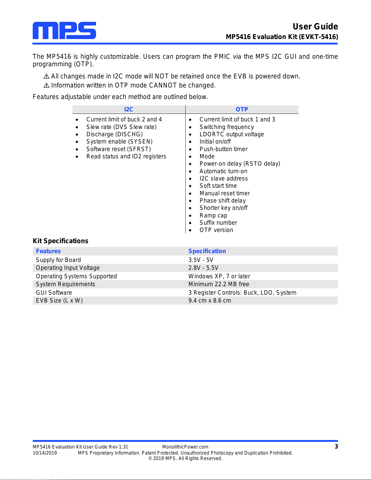
The MP5416 is highly customizable. Users can program the PMIC via the MPS I2C GUI and one-time
programming (OTP).
All changes made in I2C mode will NOT be retained once the EVB is powered down.
Information written in OTP mode CANNOT be changed.
Features adjustable under each method are outlined below.
I2C
OTP
Current limit of buck 2 and 4
Slew rate (DVS Slew rate)
Discharge (DISCHG)
System enable (SYSEN)
Software reset (SFRST)
Read status and ID2 registers
Current limit of buck 1 and 3
Switching frequency
LDORTC output voltage
Initial on/off
Push-button timer
Mode
Power-on delay (RSTO delay)
Automatic turn-on
I2C slave address
Soft start time
Manual reset timer
Phase shift delay
Shorter key on/off
Ramp cap
Suffix number
OTP version
Kit Specifications
Features
Specification
Supply for Board
3.5V - 5V
Operating Input Voltage
2.8V - 5.5V
Operating Systems Supported
Windows XP, 7 or later
System Requirements
Minimum 22.2 MB free
GUI Software
3 Register Controls: Buck, LDO, System
EVB Size (L x W)
9.4 cm x 8.6 cm

User Guide
MP5416 Evaluation Kit (EVKT-5416)
MP5416 Evaluation Kit User Guide Rev 1.31 MonolithicPower.com 4
10/14/2019 MPS Proprietary Information. Patent Protected. Unauthorized Photocopy and Duplication Prohibited.
© 2019 MPS. All Rights Reserved.
Section 1. Hardware Specifications
1.1 Personal Computer Requirements
The following must be minimally met to use the EVKT-5416.
Operating system of Windows XP, 7, or later
Net Framework 4.0
PC with a minimum of one available USB port
At least 22.2 MB of free space
1.2 EV5416-R-00D Specifications
The EV5416-R-00D is anevaluation boardfor the MP5416GR-CCCC. For more information, please refer
to the EV5416-R-00D datasheet.
Figure 2: EV5416-R-00D Evaluation Board
1.3 EVKT-USBI2C-02 Specifications
The EVKT-USBI2C-02 refers to the USB to I2C communication interface device, which connects the EVB
and the PC, and its supporting accessories. It provides I2C and PMBus capabilities. Together with MPS
Virtual Bench Pro and GUI tools, it provides a quick and easy way to evaluate the performance of MPS
digital products. For more details, refer to the EVKT-USBI2C-02 datasheet.
Figure 3: EVKT-USBI2C-02 Communication Interface Device
Feature
Specification
Supply for Evaluation Board
3.5V - 5V
Operating Input Voltage
2.8V - 5.5V
EVB Size (L x W)
9.4cm x 8.6cm
User Guide
MP5416 Evaluation Kit (EVKT-5416)
MP5416 Evaluation Kit User Guide Rev 1.31 MonolithicPower.com 5
10/14/2019 MPS Proprietary Information. Patent Protected. Unauthorized Photocopy and Duplication Prohibited.
© 2019 MPS. All Rights Reserved.
Section 2. Software Requirements
2.1 Software Installation Procedure
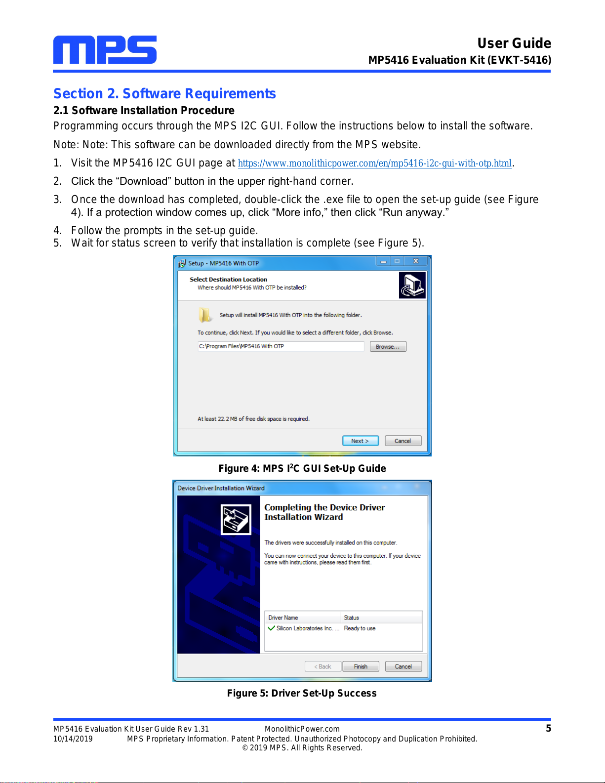
Programming occurs through the MPS I2C GUI. Follow the instructions below to install the software.
Note: Note: This software can be downloaded directly from the MPS website.
1. Visit the MP5416 I2C GUI page at https://www.monolithicpower.com/en/mp5416-i2c-gui-with-otp.html.
2. Click the “Download” button in the upper right-hand corner.
3. Once the download has completed, double-click the .exe file to open the set-up guide (see Figure
4). If a protection window comes up, click “More info,” then click “Run anyway.”
4. Follow the prompts in the set-up guide.
5. Wait for status screen to verify that installation is complete (see Figure 5).
Figure 4: MPS I2C GUI Set-Up Guide
Figure 5: Driver Set-Up Success

User Guide
MP5416 Evaluation Kit (EVKT-5416)
MP5416 Evaluation Kit User Guide Rev 1.31 MonolithicPower.com 6
10/14/2019 MPS Proprietary Information. Patent Protected. Unauthorized Photocopy and Duplication Prohibited.
© 2019 MPS. All Rights Reserved.
Section 3. Evaluation Kit Test Set-up
3.1 Hardware Set-Up
The hardware must be properly configured prior to use. Follow the instructions below to set up the EVB.
1. Locate the proper wires to connect the EVB to the EVKT-USBI2C-02 communication interface device.
2. Connect SCL, SDA, and GND (see Figure 6). If needed, refer to the datasheet for further clarification.
3. Use the USB cable to connect the EVKT-USBI2C-02 communication interface device to the PC and
follow the instructions below to set up the EVB.
Figure 6: EVB to MPS I2C Communication Interface Device Wire Connection
3.2 Powering up the EVB
1. Connect the positive and negative terminals of the load to the VOUT and GND pins, respectively.
2. Preset the power supply output between 3.5V and 5V, then turn off the power supply.
3. Connect the positive and negative terminals of the power supply output to the VIN and GND pins,
respectively.
4. Turn the power supply on.
5. Press the P1 button on the EVB. The PMIC will enter the power on sequence automatically.
3.3 Software Set-Up
After connecting the hardware according to steps above, follow the steps below to use the GUI software.
1. Start the software. It will automatically check the EVB connection.
If connection is successful, the address will be listed in the “Slave Address” (see Figure 7).

User Guide
MP5416 Evaluation Kit (EVKT-5416)
MP5416 Evaluation Kit User Guide Rev 1.31 MonolithicPower.com 7
10/14/2019 MPS Proprietary Information. Patent Protected. Unauthorized Photocopy and Duplication Prohibited.
© 2019 MPS. All Rights Reserved.
Figure 7: Appearance of Address Shows Successful Connection
If not, one of two warnings will appear at the bottom:
1) “No Slave Found. Please Check the Connection!” This means that the evaluation board is
not connected (see Figure 8).
2) “Device is not available. Please check the Connection!” This means that the USB I2C
communication interface device is not connected (see Figure 9).
Figure 8: Warning Indicates Unsuccessful Connection –Evaluation Board Not Connected

User Guide
MP5416 Evaluation Kit (EVKT-5416)
MP5416 Evaluation Kit User Guide Rev 1.31 MonolithicPower.com 8
10/14/2019 MPS Proprietary Information. Patent Protected. Unauthorized Photocopy and Duplication Prohibited.
© 2019 MPS. All Rights Reserved.
Figure 9: Warning Indicates Unsuccessful Connection –USBI2C Communication Interface Device is Not
Connected
2. If connection is successful, proceed to Step 3. Otherwise, check connections between the EVB,
communication interface device, and PC. Re-plug the USB into the computer and restart the GUI.
3. Select MP5416 UNLOCK from under Part Numbers. The Register Control menu will appear on the
left side. I2C register values will be read automatically and displayed on the right (see Figure 10).
Figure 10: Values from I2C Shown in Table
4. Find the item you want to change and select the desired value from the drop down menu.

User Guide
MP5416 Evaluation Kit (EVKT-5416)
MP5416 Evaluation Kit User Guide Rev 1.31 MonolithicPower.com 9
10/14/2019 MPS Proprietary Information. Patent Protected. Unauthorized Photocopy and Duplication Prohibited.
© 2019 MPS. All Rights Reserved.
5. Click the “Read All” button to update values. The changed information of the item will appear on the
right side (see Figure 11).
Figure 11: Refer to Datasheet to Translate 0’s and 1’s
All changes made via the I2C will be restored to default values once the EVB is powered down.
3.4 Device Programming Instructions
The MP5416-CCCC can be custom-programmed. Follow the instructions outlined below to create and
export customized configurations.
1. Using a computer, open the MPS GUI software. Make sure you have powered on the EVB.
2. Ensure connection between the EVB and computer (see Figure 6).
3. Select the “MP5416Unlocked” from under Part Numbers.
4. Disable buck1/buck2/buck3/buck4 and LDO2-LDO5.
5. Select the OTP option from under GUI (see Figure 12).
Figure 12: Select OTP, Located in Task Bar
User Guide
MP5416 Evaluation Kit (EVKT-5416)
MP5416 Evaluation Kit User Guide Rev 1.31 MonolithicPower.com 10
10/14/2019 MPS Proprietary Information. Patent Protected. Unauthorized Photocopy and Duplication Prohibited.
© 2019 MPS. All Rights Reserved.
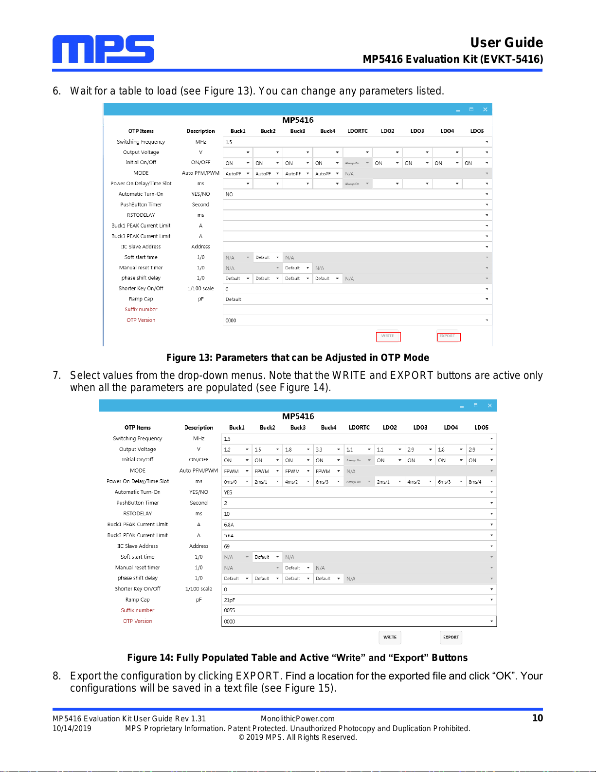
6. Wait for a table to load (see Figure 13). You can change any parameters listed.
Figure 13: Parameters that can be Adjusted in OTP Mode
7. Select values from the drop-down menus. Note that the WRITE and EXPORT buttons are active only
when all the parameters are populated (see Figure 14).
Figure 14: Fully Populated Table and Active “Write” and “Export” Buttons
8. Export the configuration by clicking EXPORT. Find a location for the exported file and click “OK”. Your
configurations will be saved in a text file (see Figure 15).

User Guide
MP5416 Evaluation Kit (EVKT-5416)
MP5416 Evaluation Kit User Guide Rev 1.31 MonolithicPower.com 11
10/14/2019 MPS Proprietary Information. Patent Protected. Unauthorized Photocopy and Duplication Prohibited.
© 2019 MPS. All Rights Reserved.
Figure 15: Various Locations Available to Export To
9. Wait for a status screen (see Figure 16).
Figure 16: Status Screen Indicates Success
10. Rename the file if you would like to refer to it at a later time. Otherwise, this file will be overwritten the
next time you perform OTP and export to the same location.
11. Check parameters carefully.
Once the information is written to the MP5416-CCCC, it cannot be changed.

User Guide
MP5416 Evaluation Kit (EVKT-5416)
MP5416 Evaluation Kit User Guide Rev 1.31 MonolithicPower.com 12
10/14/2019 MPS Proprietary Information. Patent Protected. Unauthorized Photocopy and Duplication Prohibited.
© 2019 MPS. All Rights Reserved.
12. Click the WRITE button. A window should pop up (see Figure 17).
Figure 17: Important Warning –User Must Increase Voltage
13. Increase the input voltage to a value between 6.2V and 6.5V.
14. Click “Yes” to write. Alternatively, click “No” if adjustments are needed.
15. Wait for a status screen (see Figure 18).
Figure 18: Screen Indicates that Configurations have been Written to MP5416-CCCC
16. Click OK and turn off power.
User Guide
MP5416 Evaluation Kit (EVKT-5416)
MP5416 Evaluation Kit User Guide Rev 1.31 MonolithicPower.com 13
10/14/2019 MPS Proprietary Information. Patent Protected. Unauthorized Photocopy and Duplication Prohibited.
© 2019 MPS. All Rights Reserved.
The remaining steps are optional and instruct how to check that new configurations have been
programmed.
Optional:
17. Adjust the input voltage to 3.5 - 5V.
18. Repeat steps 1-3 from this section.
19. If done correctly, new configurations will be shown in the table on the left hand side.
Notes:
Unlike in I2C, not all of the configurations you set in OTP mode will be displayed until you write to
MP5416-CCCC and power cycle.
After OTP, you:
oAre still able to change values using the I2C.
oDo not need to press P1 while powering on the board.
If you try to perform OTP on a previously programmed device, the GUI software will allow you to
proceed normally. However, your configurations will NOT be saved.
3.5 Troubleshooting Tips
Note: USBI2C-02 and USBI2C-01 drivers are not compatible. USBI2C-02 uses USBXpress and
USBI2C uses Cyusb3. USBI2C-02 is the recommended device for MPS PMBus and I2C.
EVKT-USBI2C-01
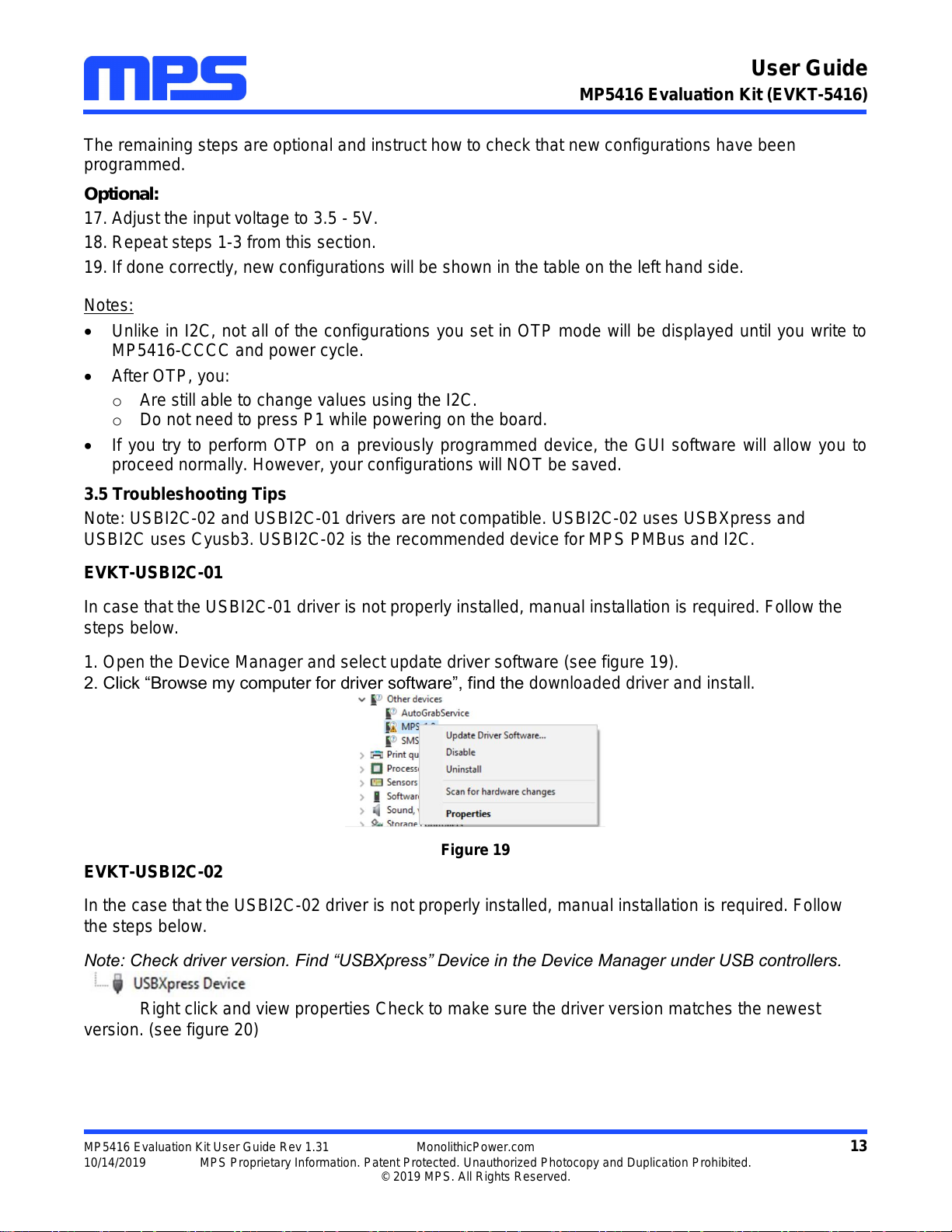
In case that the USBI2C-01 driver is not properly installed, manual installation is required. Follow the
steps below.
1. Open the Device Manager and select update driver software (see figure 19).
2. Click “Browse my computer for driver software”, find the downloaded driver and install.
Figure 19
EVKT-USBI2C-02
In the case that the USBI2C-02 driver is not properly installed, manual installation is required. Follow
the steps below.
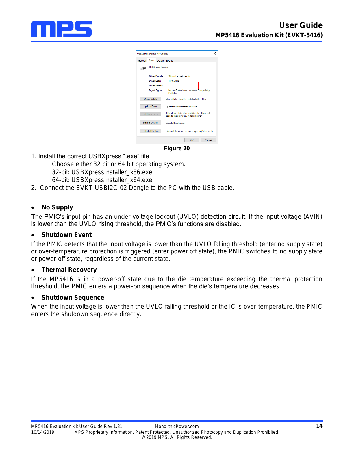
Note: Check driver version. Find “USBXpress” Device in the Device Manager under USB controllers.
Right click and view properties Check to make sure the driver version matches the newest
version. (see figure 20)
User Guide
MP5416 Evaluation Kit (EVKT-5416)
MP5416 Evaluation Kit User Guide Rev 1.31 MonolithicPower.com 14
10/14/2019 MPS Proprietary Information. Patent Protected. Unauthorized Photocopy and Duplication Prohibited.
© 2019 MPS. All Rights Reserved.
Figure 20
1. Install the correct USBXpress “.exe” file
Choose either 32 bit or 64 bit operating system.
32-bit: USBXpressInstaller_x86.exe
64-bit: USBXpressInstaller_x64.exe
2. Connect the EVKT-USBI2C-02 Dongle to the PC with the USB cable.
No Supply
The PMIC’s input pin has an under-voltage lockout (UVLO) detection circuit. If the input voltage (AVIN)
is lower than the UVLO rising threshold, the PMIC’s functions are disabled.
Shutdown Event
If the PMIC detects that the input voltage is lower than the UVLO falling threshold (enter no supply state)
or over-temperature protection is triggered (enter power off state), the PMIC switches to no supply state
or power-off state, regardless of the current state.
Thermal Recovery
If the MP5416 is in a power-off state due to the die temperature exceeding the thermal protection
threshold, the PMIC enters a power-on sequence when the die’s temperature decreases.
Shutdown Sequence
When the input voltage is lower than the UVLO falling threshold or the IC is over-temperature, the PMIC
enters the shutdown sequence directly.

User Guide
MP5416 Evaluation Kit (EVKT-5416)
MP5416 Evaluation Kit User Guide Rev 1.31 MonolithicPower.com 15
10/14/2019 MPS Proprietary Information. Patent Protected. Unauthorized Photocopy and Duplication Prohibited.
© 2019 MPS. All Rights Reserved.
Section 4. Ordering Information
The components of the evaluation kit can be purchased separately depending on user needs.
Part Number
Description
EVKT-5416
Complete evaluation kit
Contents of EVKT-5416
EV5416-R-00D
EV5416 evaluation board allowing users to perform OTP
EVKT-USBI2C-02
Includes one USB to I2C communication interface device, one USB
Male A to B cable, one 3-in ribbon cable
MP5416GR-CCCC
2 additional MP5416 ICs which can be used for OTP programming
Order directly from MonolithicPower.com or our distributors.
This manual suits for next models
1
Table of contents
Other MPS Motherboard manuals

MPS
MPS EV28163-Q-00A User manual

MPS
MPS MP2663 User manual

MPS
MPS EVKT-MP8862 User manual

MPS
MPS MagAlpha EVMA Q-00A Series Operating instructions

MPS
MPS EV20045DQ-00A User manual

MPS
MPS MP8869S User manual

MPS
MPS EV6536-U-00A User manual

MPS
MPS EV7740DN-01B User manual

MPS
MPS EV6539B-F-00A User manual

MPS
MPS EV8042DF-00B User manual

MPS
MPS EVQ4488-U-00B User manual

MPS
MPS EV2633-R-01A User manual

MPS
MPS EV2632-R-01A User manual

MPS
MPS MP2696A Reference guide

MPS
MPS EV6532-R-01A User manual

MPS
MPS MP2760 User manual

MPS
MPS EV5480-C-00A User manual

MPS
MPS EVKT-MP8833 User manual

MPS
MPS EV2602DQ-00B User manual

MPS
MPS EV2696A-Q-00B User manual


