MPS MP2663 User manual

User Guide
MP2663 Evaluation Kit (EVKT-MP2663)

User Guide
MP2663 Evaluation Kit (EVKT-MP2663)
MP2663 Evaluation Kit User Guide rev 1.0 MonolithicPower.com 1
3/13/2019 MPS Proprietary Information. Patent Protected. Unauthorized Photocopy and Duplication Prohibited.
© 2019 MPS. All Rights Reserved.
Table of Contents
Overview...................................................................................................................................................2
Introduction ...........................................................................................................................................2
Kit Contents...........................................................................................................................................2
Features and Benefits...........................................................................................................................3
Kit Specifications...................................................................................................................................3
Section 1. Hardware Specifications..........................................................................................................4
1.1 Personal Computer Requirements..................................................................................................4
1.2 EV2663-C-00A Specifications.........................................................................................................4
1.3 EVKT-USBI2C-02 Specifications ....................................................................................................4
Section 2. Software Requirements ...........................................................................................................5
2.1 Software Installation Procedure ......................................................................................................5
Section 3. Evaluation Kit Test Set-up .......................................................................................................6
3.1 Hardware Setup ..............................................................................................................................6
3.2 Powering up the EVB......................................................................................................................6
3.3 Software Set-Up..............................................................................................................................6
3.4 Device Programming Instructions ...................................................................................................8
3.5 Troubleshooting Tips.....................................................................................................................10
Section 4. Ordering Information..............................................................................................................11

User Guide
MP2663 Evaluation Kit (EVKT-MP2663)
MP2663 Evaluation Kit User Guide rev 1.0 MonolithicPower.com 2
3/13/2019 MPS Proprietary Information. Patent Protected. Unauthorized Photocopy and Duplication Prohibited.
© 2019 MPS. All Rights Reserved.
Overview
Introduction
The EVKT-MP2663 is an evaluation kit for the MP2663. This board is designed for the MP2663, which is
a highly-integrated single-cell Li-Ion/Li-Polymer battery charger with a system power-path management
function. The layout accommodates most commonly used capacitors. The default function of this board
is preset for charger mode and the charge full voltage is preset to 4.095V for 1 cell Li-Ion battery.
Kit Contents
EVKT-MP2663 kit contents (items below can be ordered separately).
#
Part Number
Item
Quantity
1
EV2663-C-00A
MP2663 evaluation board
1
2
EVKT-USBI2C-02-
BAG
Includes one USB to I2C communication interface, one USB cable,
one ribbon cable
1
3
Online resources
Includes datasheet, user guide, product brief, and GUI
1
Figure 1: EVKT-MP2663 Evaluation Kit Set-Up
User Guide
MP2663 Evaluation Kit (EVKT-MP2663)
MP2663 Evaluation Kit User Guide rev 1.0 MonolithicPower.com 3
3/13/2019 MPS Proprietary Information. Patent Protected. Unauthorized Photocopy and Duplication Prohibited.
© 2019 MPS. All Rights Reserved.
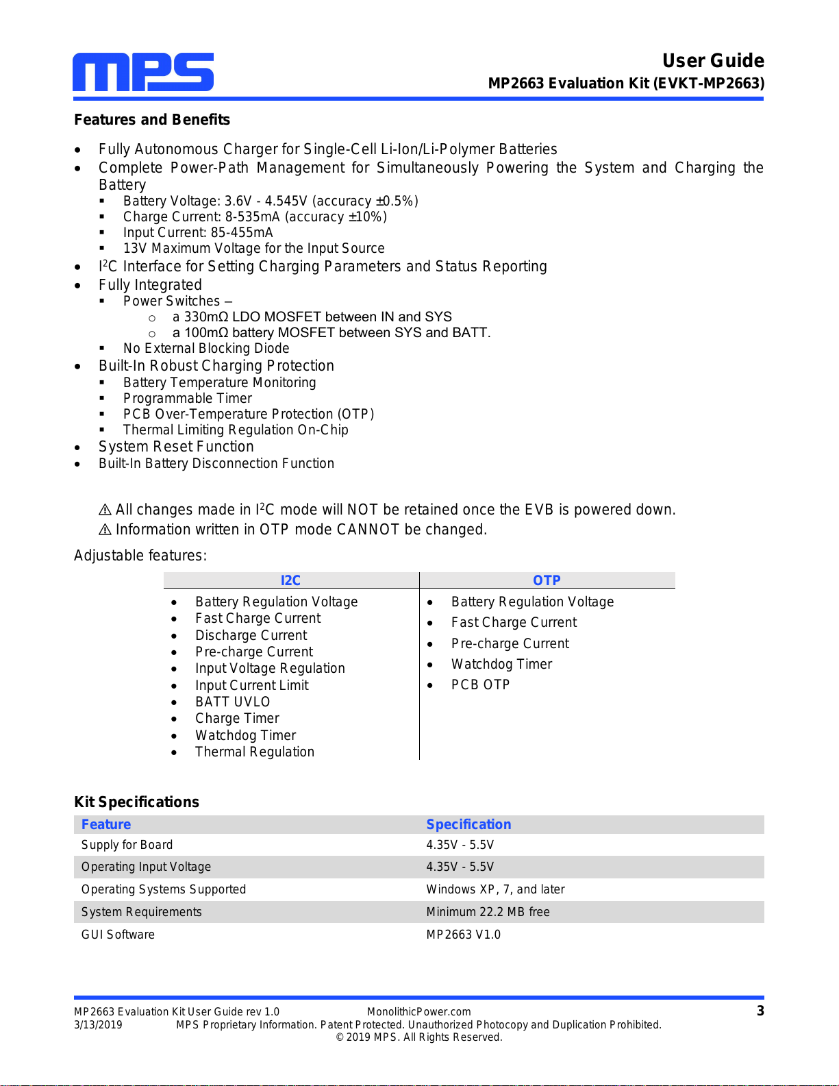
Features and Benefits
Fully Autonomous Charger for Single-Cell Li-Ion/Li-Polymer Batteries
Complete Power-Path Management for Simultaneously Powering the System and Charging the
Battery
Battery Voltage: 3.6V - 4.545V (accuracy ±0.5%)
Charge Current: 8-535mA (accuracy ±10%)
Input Current: 85-455mA
13V Maximum Voltage for the Input Source
I2C Interface for Setting Charging Parameters and Status Reporting
Fully Integrated
Power Switches –
oa 330mΩ LDO MOSFET between IN and SYS
oa 100mΩ battery MOSFET between SYS and BATT.
No External Blocking Diode
Built-In Robust Charging Protection
Battery Temperature Monitoring
Programmable Timer
PCB Over-Temperature Protection (OTP)
Thermal Limiting Regulation On-Chip
System Reset Function
Built-In Battery Disconnection Function
All changes made in I2C mode will NOT be retained once the EVB is powered down.
Information written in OTP mode CANNOT be changed.
Adjustable features:
I2C
OTP
Battery Regulation Voltage
Fast Charge Current
Discharge Current
Pre-charge Current
Input Voltage Regulation
Input Current Limit
BATT UVLO
Charge Timer
Watchdog Timer
Thermal Regulation
Battery Regulation Voltage
Fast Charge Current
Pre-charge Current
Watchdog Timer
PCB OTP
Kit Specifications
Feature
Specification
Supply for Board
4.35V - 5.5V
Operating Input Voltage
4.35V - 5.5V
Operating Systems Supported
Windows XP, 7, and later
System Requirements
Minimum 22.2 MB free
GUI Software
MP2663 V1.0

User Guide
MP2663 Evaluation Kit (EVKT-MP2663)
MP2663 Evaluation Kit User Guide rev 1.0 MonolithicPower.com 4
3/13/2019 MPS Proprietary Information. Patent Protected. Unauthorized Photocopy and Duplication Prohibited.
© 2019 MPS. All Rights Reserved.
Section 1. Hardware Specifications
1.1 Personal Computer Requirements
The following must be minimally met to use the EVKT-MP2663.
Operating System of Windows XP, 7 or later
Net Framework 4.0
PC with a minimum of one available USB port
At least 22.2 MB of free space
1.2 EV2663-C-00A Specifications
The EV2663-C-00A is an evaluation board for the MP2663. For more information, please refer to the
EV2663-C-00A datasheet.
Figure 2: EV2663-C-00A Evaluation Board
1.3 EVKT-USBI2C-02 Specifications
The EVKT-USBI2C-02 refers to the communication interface, which connects the EVB and the PC and
its supporting accessories. It provides I2C capabilities. Together with MPS Virtual Bench Pro and I2C GUI
tools, it provides a quick and easy way to evaluate the performance of MPS digital products. For more
details, refer to the EVKT-USBI2C-02 datasheet.
Figure 3: EVKT-USBI2C-02 Communication Interface
Feature
Specification
Supply for Evaluation Board
4.35V - 5.5V
Operating Input Voltage
4.35V - 5.5V
EVB Size (L X W)
6.35cm X
6.35cm

User Guide
MP2663 Evaluation Kit (EVKT-MP2663)
MP2663 Evaluation Kit User Guide rev 1.0 MonolithicPower.com 5
3/13/2019 MPS Proprietary Information. Patent Protected. Unauthorized Photocopy and Duplication Prohibited.
© 2019 MPS. All Rights Reserved.
Section 2. Software Requirements
2.1 Software Installation Procedure
Programming occurs through the MPS I2C GUI. Follow the instructions below to install the software.
Note: This software can be downloaded from the MPS website:
1. Download and extract the zip package of the “I2C evaluation kit software for MP2663” to a directory
of your choice.
2. Double click the .exe file to open the set-up guide (see Figure 4).
3. Follow the prompts in the set-up guide.
4. Wait for status screen to verify that installation is complete (see Figure 5).
Figure 4: MPS I2C GUI Set-Up Guide
Figure 5: Driver Set-Up Success

User Guide
MP2663 Evaluation Kit (EVKT-MP2663)
MP2663 Evaluation Kit User Guide rev 1.0 MonolithicPower.com 6
3/13/2019 MPS Proprietary Information. Patent Protected. Unauthorized Photocopy and Duplication Prohibited.
© 2019 MPS. All Rights Reserved.
Section 3. Evaluation Kit Test Set-up
3.1 Hardware Setup
The hardware must be properly configured prior to use. Follow the instructions below to set up the EVB.
1. Locate the proper wires to connect the EVB to the EVKT-USBI2C-02 communication interface.
2. Connect SCL, SDA, and GND (see Figure 6). If needed, refer to the datasheet for further clarification.
Figure 6: EVB to MPS I2C Communication Interface Wire Connection
3.2 Powering up the EVB
1. Connect the positive and negative terminals of the load to the SYS and GND pins, respectively.
2. Connect the positive and negative terminals of the battery to the VBATT and GND pins, respectively.
If it is a battery simulator, preset the battery voltage between 0V and 4.545V, then turn it off. Connect
the battery simulator output to the VBATT and GND pins respectively.
3. Preset the power supply output between 3.9V and 7.0V, and then turn off the power supply. Connect
the positive and negative terminals of the power supply output to the VIN and GND pins, respectively.
4. Make sure the battery voltage has been preset (if a battery simulator is used, turn on the battery
emulator). Turn the power supply on. The IC will enter the power on sequence automatically.
Reminder: if the battery simulator is connected, please make sure to turn on the battery emulator first,
before the input supply in the start-up sequence.
3.3 Software Set-Up
After connecting the hardware according to Section 3.1 and Section3.2, follow the steps below to use the
GUI software:
1. Start the software. It will check the EVB connection automatically.
If connection is successful, both the USB and MP2663 DEMO board statuses are "connected".
(See Figure 7).

User Guide
MP2663 Evaluation Kit (EVKT-MP2663)
MP2663 Evaluation Kit User Guide rev 1.0 MonolithicPower.com 7
3/13/2019 MPS Proprietary Information. Patent Protected. Unauthorized Photocopy and Duplication Prohibited.
© 2019 MPS. All Rights Reserved.
Figure 7: Appearance of USB and MP2663 EVB Board Show Connected
If connection is not successful, "Not Connected" will appear in red. Check connections between
the EVB, communication interface, and PC. Re-plug the USB into the computer.
1) MP2663 DEMO Board “Not Connected" means that the evaluation board is not connected
correctly.
2) USB “Not Connected" means that the USB I2C communication interface is not connected
correctly.
2. Click the “Read All Register” button to read the I2C register values and the default values are
displayed (see Figure 7).
3. Find the item you want to change and select the desired value from the drop down menu.
4. Click the “Write All” button to update values. The changed information of the item will be downloaded
to the IC.
All changes made via the I2C will be restored to default values once the EVB is powered down.
User Guide
MP2663 Evaluation Kit (EVKT-MP2663)
MP2663 Evaluation Kit User Guide rev 1.0 MonolithicPower.com 8
3/13/2019 MPS Proprietary Information. Patent Protected. Unauthorized Photocopy and Duplication Prohibited.
© 2019 MPS. All Rights Reserved.
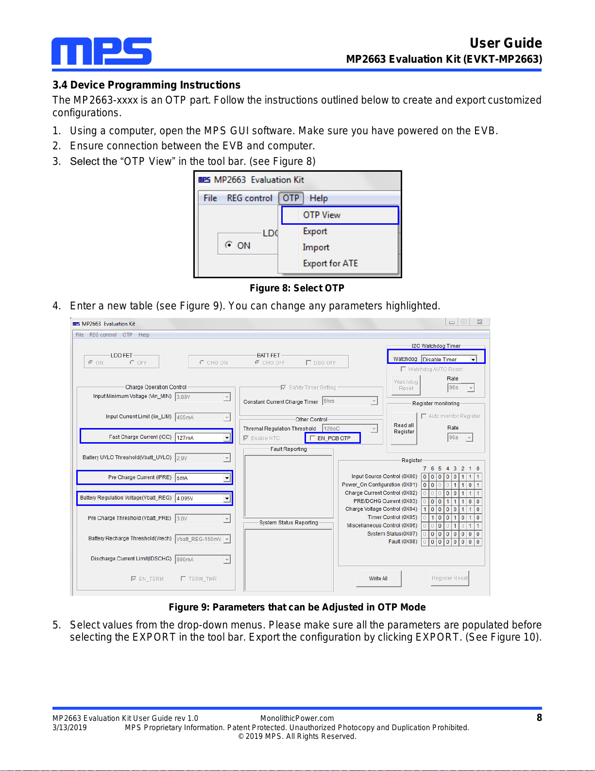
3.4 Device Programming Instructions
The MP2663-xxxx is an OTP part. Follow the instructions outlined below to create and export customized
configurations.
1. Using a computer, open the MPS GUI software. Make sure you have powered on the EVB.
2. Ensure connection between the EVB and computer.
3. Select the “OTP View” in the tool bar. (see Figure 8)
Figure 8: Select OTP
4. Enter a new table (see Figure 9). You can change any parameters highlighted.
Figure 9: Parameters that can be Adjusted in OTP Mode
5. Select values from the drop-down menus. Please make sure all the parameters are populated before
selecting the EXPORT in the tool bar. Export the configuration by clicking EXPORT. (See Figure 10).

User Guide
MP2663 Evaluation Kit (EVKT-MP2663)
MP2663 Evaluation Kit User Guide rev 1.0 MonolithicPower.com 9
3/13/2019 MPS Proprietary Information. Patent Protected. Unauthorized Photocopy and Duplication Prohibited.
© 2019 MPS. All Rights Reserved.
Figure 10: Select “Export”
6. Find a location for the exported file and click “Save”. Your configurations will be saved in a .txt file
(see Figure 11).
Figure 11: Various Export Locations Available
7. Send this file to an FAE and apply for the customized "xxxx" code.
User Guide
MP2663 Evaluation Kit (EVKT-MP2663)
MP2663 Evaluation Kit User Guide rev 1.0 MonolithicPower.com 10
3/13/2019 MPS Proprietary Information. Patent Protected. Unauthorized Photocopy and Duplication Prohibited.
© 2019 MPS. All Rights Reserved.
3.5 Troubleshooting Tips
EVKT-USBI2C-02 Driver Problem
If the USBI2C-02 driver is not properly installed, manual installation is required. Follow the steps below.
1. Install the correct “.exe” file according to the windows operation system.
32-bit: \EVKT-USBI2C-02 USB Driver\USBXpressInstaller_x86.exe.
64-bit: \EVKT-USBI2C-02 USB Driver\USBXpressInstaller_x64.exe.
2. Connect the communication interface to the PC with a USB cable.
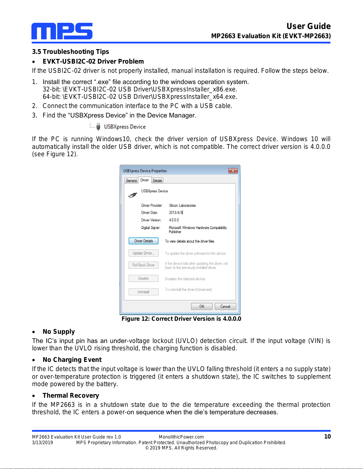
3. Find the “USBXpress Device” in the Device Manager.
If the PC is running Windows10, check the driver version of USBXpress Device. Windows 10 will
automatically install the older USB driver, which is not compatible. The correct driver version is 4.0.0.0
(see Figure 12).
Figure 12: Correct Driver Version is 4.0.0.0
No Supply
The IC’s input pin has an under-voltage lockout (UVLO) detection circuit. If the input voltage (VIN) is
lower than the UVLO rising threshold, the charging function is disabled.
No Charging Event
If the IC detects that the input voltage is lower than the UVLO falling threshold (it enters a no supply state)
or over-temperature protection is triggered (it enters a shutdown state), the IC switches to supplement
mode powered by the battery.
Thermal Recovery
If the MP2663 is in a shutdown state due to the die temperature exceeding the thermal protection
threshold, the IC enters a power-on sequence when the die’s temperature decreases.

User Guide
MP2663 Evaluation Kit (EVKT-MP2663)
MP2663 Evaluation Kit User Guide rev 1.0 MonolithicPower.com 11
3/13/2019 MPS Proprietary Information. Patent Protected. Unauthorized Photocopy and Duplication Prohibited.
© 2019 MPS. All Rights Reserved.
Section 4. Ordering Information
The components of the evaluation kit can be purchased separately.
Part Number
Description
EVKT-MP2663
Complete evaluation kit
Contents of EVKT-MP2663
EV2663-C-00A
MP2663-xxxx evaluation board
EVKT-USBI2C-02
Includes one USB to I2C communication interface, one USB cable,
one ribbon cable,
Online resources
Includes datasheet, user guide, product brief, and GUI
Order directly from MonolithicPower.com or our distributors.
This manual suits for next models
1
Table of contents
Other MPS Motherboard manuals


 manual ")


