MPS MP2760 User manual

USER GUIDE –MP2760 EVALUATION KIT (EVKT-MP2760)
MP2760 Evaluation Kit User Guide Rev. 0.8 MonolithicPower.com 1
2/17/2023 MPS Proprietary Information. Patent Protected. Unauthorized Photocopy and Duplication Prohibited.
Preliminary Specifications Subject to Change © 2023 MPS. All Rights Reserved.
User Guide
MP2760 Evaluation Kit (EVKT-MP2760)
USER GUIDE –MP2760 EVALUATION KIT (EVKT-MP2760)
MP2760 Evaluation Kit User Guide Rev. 1.0 MonolithicPower.com 2
2/17/2023 MPS Proprietary Information. Patent Protected. Unauthorized Photocopy and Duplication Prohibited.
© 2023 MPS. All Rights Reserved.
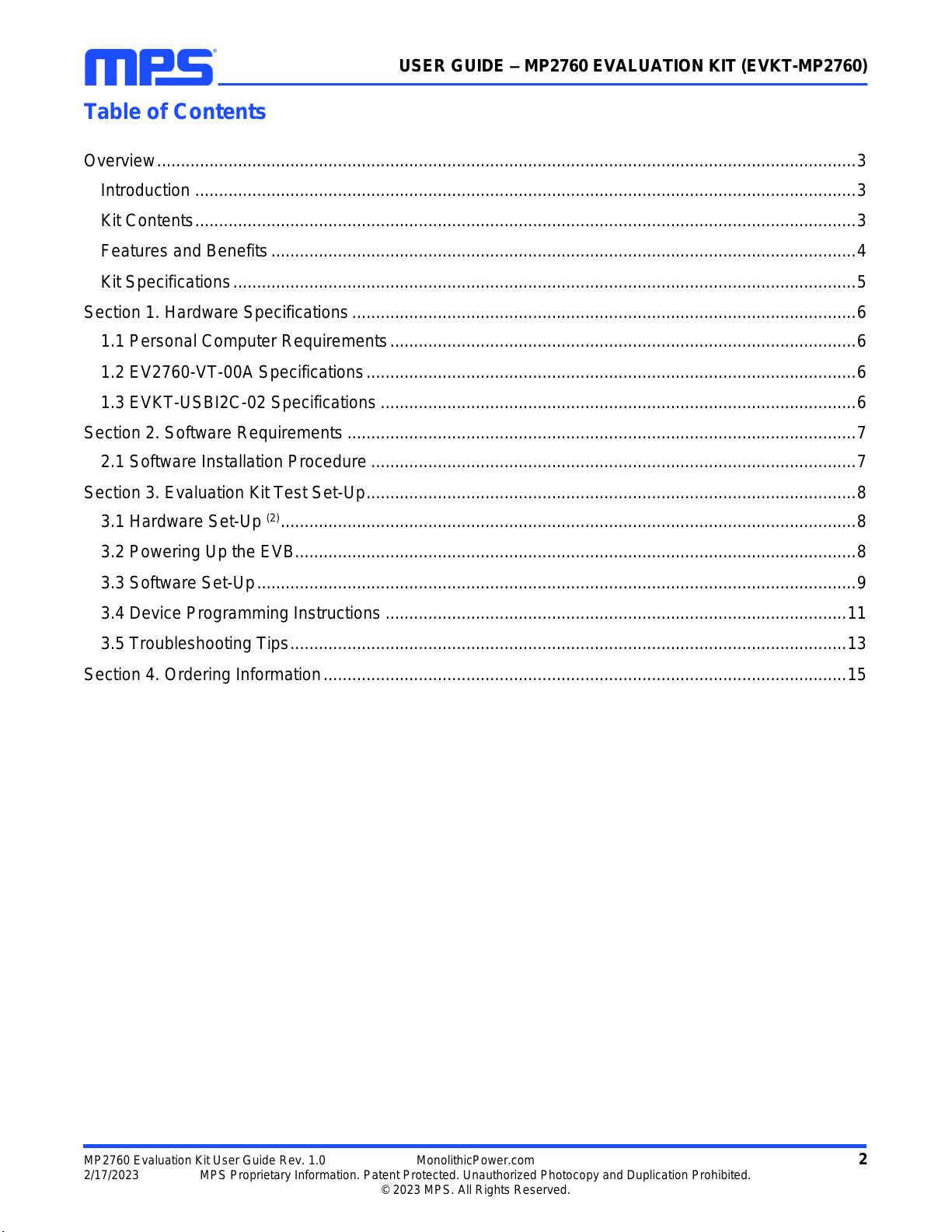
Table of Contents
Overview...................................................................................................................................................3
Introduction ...........................................................................................................................................3
Kit Contents...........................................................................................................................................3
Features and Benefits...........................................................................................................................4
Kit Specifications...................................................................................................................................5
Section 1. Hardware Specifications..........................................................................................................6
1.1 Personal Computer Requirements..................................................................................................6
1.2 EV2760-VT-00A Specifications.......................................................................................................6
1.3 EVKT-USBI2C-02 Specifications ....................................................................................................6
Section 2. Software Requirements ...........................................................................................................7
2.1 Software Installation Procedure ......................................................................................................7
Section 3. Evaluation Kit Test Set-Up.......................................................................................................8
3.1 Hardware Set-Up (2).........................................................................................................................8
3.2 Powering Up the EVB......................................................................................................................8
3.3 Software Set-Up..............................................................................................................................9
3.4 Device Programming Instructions .................................................................................................11
3.5 Troubleshooting Tips.....................................................................................................................13
Section 4. Ordering Information..............................................................................................................15

USER GUIDE –MP2760 EVALUATION KIT (EVKT-MP2760)
MP2760 Evaluation Kit User Guide Rev. 1.0 MonolithicPower.com 3
2/17/2023 MPS Proprietary Information. Patent Protected. Unauthorized Photocopy and Duplication Prohibited.
© 2023 MPS. All Rights Reserved.
Overview
Introduction
Optimized Performance with MPS MPL-AL5030 Inductor Series
The EVKT-MP2760 is an evaluation kit for the MP2760. The board is designed to demonstrate the
capabilities of the MP2760, a buck-boost narrow-voltage DC (NVDC) charger IC for battery packs with 1
to 4 cells in series. The device accepts a wide 4V to 22V input voltage (VIN) range to charge the battery
and power the load connected on the SYS pin. It also supplies a wide 3V to 21V voltage range at the IN
pin when source mode is enabled, which is compliant with USB powered device (PD) specifications.
Kit Contents
EVKT-MP2760 kit contents (items below can be ordered separately):
#
Part Number
Item
Quantity
1
EV2760-VT-00A
MP2760-0000 evaluation board
1
2
EVKT-USBI2C-02 bag
Includes one USB to I2C communication interface, one USB
cable, and one ribbon cable
1
3
Online resources
Includes GUI and supplemental documents
-
USB to I2C
Communication
Interface
USB Cable
Ribbon Cable
Input Power
Supply
EV2760-VT-00A
GUI
Battery
Load
GUI
Figure 1: EVKT-MP2760 Evaluation Kit Set-Up
USER GUIDE –MP2760 EVALUATION KIT (EVKT-MP2760)
MP2760 Evaluation Kit User Guide Rev. 1.0 MonolithicPower.com 4
2/17/2023 MPS Proprietary Information. Patent Protected. Unauthorized Photocopy and Duplication Prohibited.
© 2023 MPS. All Rights Reserved.
Features and Benefits
Optimized Performance with MPS Inductor
•Fully Integrated Buck-Boost Charger with Low On Resistance (RDS(ON)) Power MOSFETs for 1 to 4
Cells in Series Battery Pack
•Integrated N-Channel MOSFET Driver for Narrow-Voltage DC (NVDC) Power Path Control
•Integrated N-Channel MOSFET Driver for Input Power Pass-Through
•Wide Operating Range:
o4V to 22V Operating Input Voltage (VIN)
o3V to 21V Reverse Output Voltage (VOUT) with 20mV/Step
oUp to 6A Input Current (IIN) Limit with 50mA/Step
oUp to 6A Charge Current with 50mA/Step
oUp to 6A Output Current (IOUT) with 50mA/Step
o3.4V/Cell to 4.67V/Cell Battery-Full Voltage with 0.5% Accuracy
o4V to 20.4V Minimum VIN Limit with 80mV/Step
o500kHz to 1.2MHz Switching Frequency (fSW)
•I2C or SMBus Host Control Interface to Support Flexible Parameter Setting and Status Reporting
•Integrated 10-Bit Analog-to-Digital Converter (ADC) for Voltage, Current, and Temperature
Monitoring
•Analog Output Pin to Monitor Charge Current
•Built-In Robust Protections:
oInput Over-Voltage Protection (OVP)
oBattery OVP
oOutput Short-Circuit Protection (SCP) in Source Mode
oBattery Missing Detection
oNTC Pin Floating Detection
oConfigurable JEITA for Battery Temperature Protection
oThermal Regulation and Thermal Shutdown
oSafety Charge Timer
•Available in a TQFN-30 (4mmx5mm) Package
All changes made in I2C mode are not retained once the evaluation board shuts down.
Information written in OTP mode cannot be changed.

USER GUIDE –MP2760 EVALUATION KIT (EVKT-MP2760)
MP2760 Evaluation Kit User Guide Rev. 1.0 MonolithicPower.com 5
2/17/2023 MPS Proprietary Information. Patent Protected. Unauthorized Photocopy and Duplication Prohibited.
© 2023 MPS. All Rights Reserved.
Adjustable Features
I2C
OTP
•Charge currents (ITC, IPRE, ICC, and
ITERM)
•Battery cell number and battery-full
voltage
•Minimum system voltage (VSYS_MIN)
regulation
•Input minimum voltage regulation
(VIN_MIN)
•Input current limit (IIN_LIM) regulation
•Switching frequency (fSW)
•Output voltage (VOUT) in source
mode
•Output current (IOUT) limit in source
mode
•Safety charge timer
•Over-voltage protection (OVP)
thresholds
•Under-voltage (UV) thresholds
•Negative temperature coefficient
(NTC) thresholds
•Thermal regulation
•Charge currents (ITC, IPRE, ICC, and
ITERM)
•Battery cell number and battery-full
voltage
•VSYS_MIN regulation voltage
•VIN_MIN regulation voltage
•IIN_LIM regulation
•fSW
Kit Specifications
Features
Specifications
Supply for Board
4V to 22V
Operating Input Voltage
4V to 22V
Battery Regulation Voltage
3.6V/Cell to 4.68V/Cell
Fast Charge Current
Up to 6000mA
Minimum System Voltage (1)
2.4V to 16.8V
Minimum Input Voltage Regulation
4V to 20.4V
Input Current Limit
Up to 6000mA
Output Voltage in Source Mode
3V to 21V
Operating Systems Supported
Windows XP, 7, or later
System Requirements
Minimum 22.2MB free
GUI Software
MP2760 programming tool
EVB Size (LxW)
8.9cmx8.9cm
Note:
1) It is recommended to set the value according to the battery cell count.
USER GUIDE –MP2760 EVALUATION KIT (EVKT-MP2760)
MP2760 Evaluation Kit User Guide Rev. 1.0 MonolithicPower.com 6
2/17/2023 MPS Proprietary Information. Patent Protected. Unauthorized Photocopy and Duplication Prohibited.
© 2023 MPS. All Rights Reserved.
Section 1. Hardware Specifications
1.1 Personal Computer Requirements
The following minimum conditions must be met to use the EVKT-MP2760:
•Operating system of Windows XP, 7, or later
•Net Framework 4.0
•PC with a minimum of one available USB port
•At least 22.2MB of free space
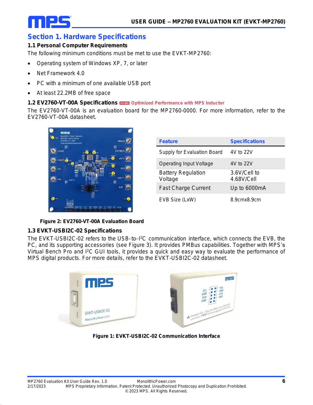
1.2 EV2760-VT-00A Specifications Optimized Performance with MPS Inductor
The EV2760-VT-00A is an evaluation board for the MP2760-0000. For more information, refer to the
EV2760-VT-00A datasheet.
Figure 2: EV2760-VT-00A Evaluation Board
1.3 EVKT-USBI2C-02 Specifications
The EVKT-USBI2C-02 refers to the USB-to-I2C communication interface, which connects the EVB, the
PC, and its supporting accessories (see Figure 3). It provides PMBus capabilities. Together with MPS’s
Virtual Bench Pro and I2C GUI tools, it provides a quick and easy way to evaluate the performance of
MPS digital products. For more details, refer to the EVKT-USBI2C-02 datasheet.
Figure 1: EVKT-USBI2C-02 Communication Interface
Feature
Specifications
Supply for Evaluation Board
4V to 22V
Operating Input Voltage
4V to 22V
Battery Regulation
Voltage
3.6V/Cell to
4.68V/Cell
Fast Charge Current
Up to 6000mA
EVB Size (LxW)
8.9cmx8.9cm
USER GUIDE –MP2760 EVALUATION KIT (EVKT-MP2760)
MP2760 Evaluation Kit User Guide Rev. 1.0 MonolithicPower.com 7
2/17/2023 MPS Proprietary Information. Patent Protected. Unauthorized Photocopy and Duplication Prohibited.
© 2023 MPS. All Rights Reserved.
Section 2. Software Requirements
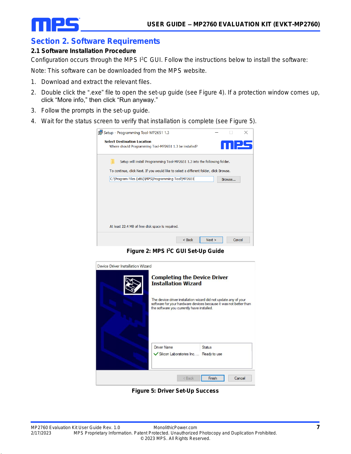
2.1 Software Installation Procedure
Configuration occurs through the MPS I2C GUI. Follow the instructions below to install the software:
Note: This software can be downloaded from the MPS website.
1. Download and extract the relevant files.
2. Double click the “.exe”file to open the set-up guide (see Figure 4). If a protection window comes up,
click “More info,” then click “Run anyway.”
3. Follow the prompts in the set-up guide.
4. Wait for the status screen to verify that installation is complete (see Figure 5).
Figure 2: MPS I2C GUI Set-Up Guide
Figure 5: Driver Set-Up Success
USER GUIDE –MP2760 EVALUATION KIT (EVKT-MP2760)
MP2760 Evaluation Kit User Guide Rev. 1.0 MonolithicPower.com 8
2/17/2023 MPS Proprietary Information. Patent Protected. Unauthorized Photocopy and Duplication Prohibited.
© 2023 MPS. All Rights Reserved.
Section 3. Evaluation Kit Test Set-Up
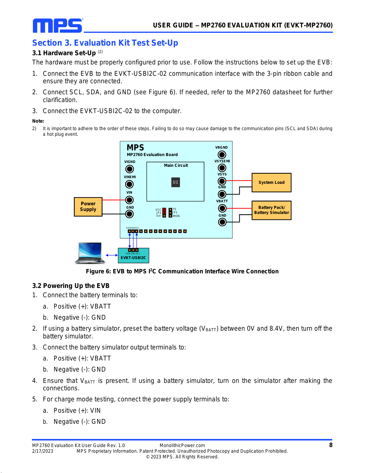
3.1 Hardware Set-Up (2)
The hardware must be properly configured prior to use. Follow the instructions below to set up the EVB:
1. Connect the EVB to the EVKT-USBI2C-02 communication interface with the 3-pin ribbon cable and
ensure they are connected.
2. Connect SCL, SDA, and GND (see Figure 6). If needed, refer to the MP2760 datasheet for further
clarification.
3. Connect the EVKT-USBI2C-02 to the computer.
Note:
2) It is important to adhere to the order of these steps. Failing to do so may cause damage to the communication pins (SCL and SDA) during
a hot plug event.
EVKT-USBI2C
U1
Main Circuit
VBATT
Battery Pack/
Battery Simulator
GND
VIN
Power
Supply GND
MP2760 Evaluation Board
MPS
VCC TS
Ext
JP2 JP1
VINEMI
IMON
VIGND VSYSEMI
GND
VBGND
VSYS
System Load
SDA SCL
GND
SDA SCLGND
Figure 6: EVB to MPS I2C Communication Interface Wire Connection
3.2 Powering Up the EVB
1. Connect the battery terminals to:
a. Positive (+): VBATT
b. Negative (-): GND
2. If using a battery simulator, preset the battery voltage (VBATT) between 0V and 8.4V, then turn off the
battery simulator.
3. Connect the battery simulator output terminals to:
a. Positive (+): VBATT
b. Negative (-): GND
4. Ensure that VBATT is present. If using a battery simulator, turn on the simulator after making the
connections.
5. For charge mode testing, connect the power supply terminals to:
a. Positive (+): VIN
b. Negative (-): GND

USER GUIDE –MP2760 EVALUATION KIT (EVKT-MP2760)
MP2760 Evaluation Kit User Guide Rev. 1.0 MonolithicPower.com 9
2/17/2023 MPS Proprietary Information. Patent Protected. Unauthorized Photocopy and Duplication Prohibited.
© 2023 MPS. All Rights Reserved.
6. Preset the power supply output between 4V and 22V, then turn on the power supply.
7. For source mode testing, connect the load terminals to:
a. Positive (+): VIN
b. Negative (-): GND
8. Connect the system load terminals to:
a. Positive (+): VSYS
b. Negative (-): GND
9. For EMI testing, connect the input or load terminals to:
a. Positive (+): VINEMI
b. Negative (-): VIGND
Connect the system load terminals to:
c. Positive (+): VSYSEMI
d. Negative (-): VBGND
10. Remove all other connectors (VIN, GND, VBATT, and GND) and pin headers.
3.3 Software Set-Up
After connecting the hardware according to the steps above, follow the steps below to use the GUI
software:
1. Start the software. It should automatically check the EVB connection.
•If the connection is successful, “Device connected” is listed at the bottom (see Figure 7).
Figure 7: Status Shows Successful Connection
•If the connection is unsuccessful, a warning appears at the bottom. There are two warnings that
the user can expect:
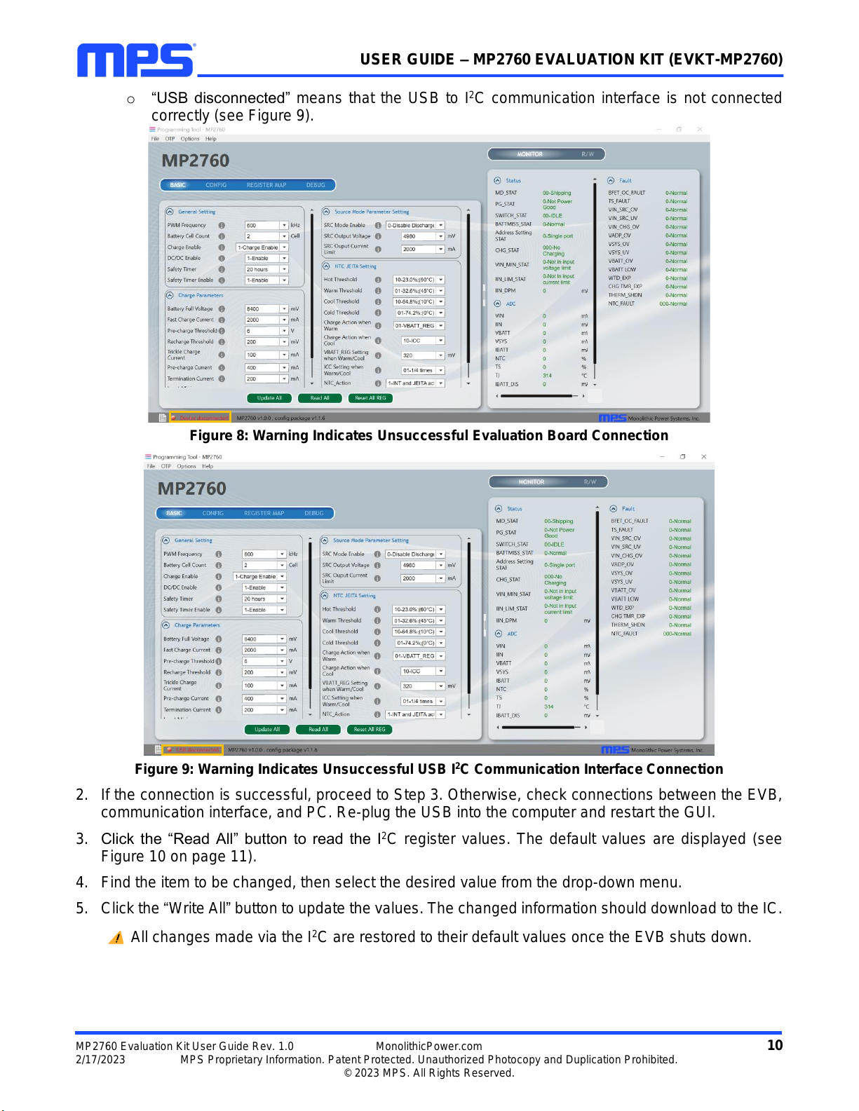
o“Device disconnected” means that the evaluation board is not connected correctly (see Figure
8 on page 10).
USER GUIDE –MP2760 EVALUATION KIT (EVKT-MP2760)
MP2760 Evaluation Kit User Guide Rev. 1.0 MonolithicPower.com 10
2/17/2023 MPS Proprietary Information. Patent Protected. Unauthorized Photocopy and Duplication Prohibited.
© 2023 MPS. All Rights Reserved.
o“USB disconnected” means that the USB to I2C communication interface is not connected
correctly (see Figure 9).
Figure 8: Warning Indicates Unsuccessful Evaluation Board Connection
Figure 9: Warning Indicates Unsuccessful USB I2C Communication Interface Connection
2. If the connection is successful, proceed to Step 3. Otherwise, check connections between the EVB,
communication interface, and PC. Re-plug the USB into the computer and restart the GUI.
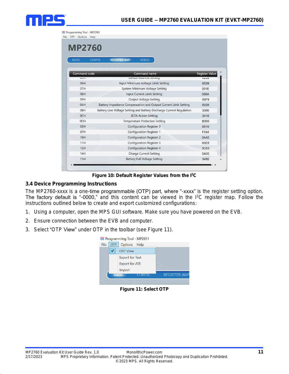
3. Click the “Read All” button to read the I2C register values. The default values are displayed (see
Figure 10 on page 11).
4. Find the item to be changed, then select the desired value from the drop-down menu.
5. Click the “Write All”button to update the values. The changed information should download to the IC.
All changes made via the I2C are restored to their default values once the EVB shuts down.
USER GUIDE –MP2760 EVALUATION KIT (EVKT-MP2760)
MP2760 Evaluation Kit User Guide Rev. 1.0 MonolithicPower.com 11
2/17/2023 MPS Proprietary Information. Patent Protected. Unauthorized Photocopy and Duplication Prohibited.
© 2023 MPS. All Rights Reserved.
Figure 10: Default Register Values from the I2C
3.4 Device Programming Instructions
The MP2760-xxxx is a one-time programmable (OTP) part, where “-xxxx” is the register setting option.
The factory default is “-0000,” and this content can be viewed in the I2C register map. Follow the
instructions outlined below to create and export customized configurations:
1. Using a computer, open the MPS GUI software. Make sure you have powered on the EVB.
2. Ensure connection between the EVB and computer.
3. Select “OTP View” under OTP in the toolbar (see Figure 11).
Figure 11: Select OTP

USER GUIDE –MP2760 EVALUATION KIT (EVKT-MP2760)
MP2760 Evaluation Kit User Guide Rev. 1.0 MonolithicPower.com 12
2/17/2023 MPS Proprietary Information. Patent Protected. Unauthorized Photocopy and Duplication Prohibited.
© 2023 MPS. All Rights Reserved.
4. Enter a new table in OTP view (see Figure 12). All selectable parameters can be changed.
Figure 12: Adjustable Parameters in OTP Mode
5. Select the desired values from the drop-down menus.
6. Ensure that all the parameters are inputted before selecting “Export for test” in the toolbar.
7. Click “Export” to export the selected configurations (see Figure 13).
Figure 13: Export the Fully Populated Table

USER GUIDE –MP2760 EVALUATION KIT (EVKT-MP2760)
MP2760 Evaluation Kit User Guide Rev. 1.0 MonolithicPower.com 13
2/17/2023 MPS Proprietary Information. Patent Protected. Unauthorized Photocopy and Duplication Prohibited.
© 2023 MPS. All Rights Reserved.
8. Find a location for the exported file and click “Save”. The configurations are saved in a text file (see
Figure 14 on page 13).
Figure 14: Save the Exported Configurations
9. Send this file to an MPS FAE to request a custom “-xxxx” code.
3.5 Troubleshooting Tips
EVKT-USBI2C-02 Driver Installation Problem
If the USBI2C-02 driver is not properly installed, manual installation is required. Follow the steps below
to manually install the EVKT-USBI2C-02 driver:
Note: Find “USBXpress Device” in the Device Manager.
If the PC is running Windows 10, check the driver version of USBXpress Device. Windows 10
automatically installs the older USB driver, which is not compatible. The correct driver version is 4.0.0.0
(see Figure 15 on page 13).
1. Install the correct "USBXpress “.exe” file. Choose either the 32-bit or 64-bit operating system.
32-bit: USBXpressInstaller_x86.exe
64-bit: USBXpressInstaller_x64.exe
2. Connect the EVKT-USBI2C-02 communication interface to the PC with the USB cable.
Figure 15: Correct Driver Version

USER GUIDE –MP2760 EVALUATION KIT (EVKT-MP2760)
MP2760 Evaluation Kit User Guide Rev. 1.0 MonolithicPower.com 14
2/17/2023 MPS Proprietary Information. Patent Protected. Unauthorized Photocopy and Duplication Prohibited.
© 2023 MPS. All Rights Reserved.
No Supply
The IC’s input pin has an under-voltage lockout (UVLO) detection circuit. If the input voltage (VIN) is below
the UVLO rising threshold, the PMIC’s functions are disabled.
Shutdown Event
If the IC detects that VIN is below the UVLO falling threshold (enter no supply state) or over-temperature
protection is triggered (enter shutdown state), then the IC switches to a no supply state or shutdown
state, regardless of the current state.
Thermal Recovery
If the MP2760 is in a shutdown state due to the die temperature exceeding the thermal protection
threshold, then the IC starts up again once the die temperature decreases.
USER GUIDE –MP2760 EVALUATION KIT (EVKT-MP2760)
MP2760 Evaluation Kit User Guide Rev. 1.0 MonolithicPower.com 15
2/17/2023 MPS Proprietary Information. Patent Protected. Unauthorized Photocopy and Duplication Prohibited.
© 2023 MPS. All Rights Reserved.
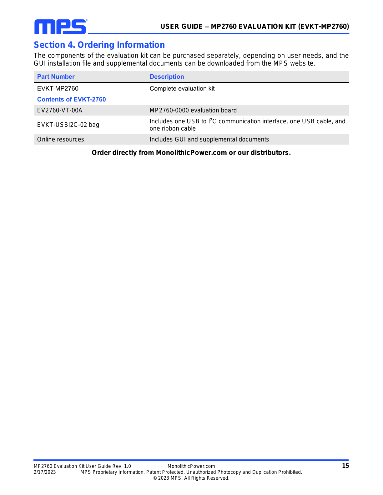
Section 4. Ordering Information
The components of the evaluation kit can be purchased separately, depending on user needs, and the
GUI installation file and supplemental documents can be downloaded from the MPS website.
Part Number
Description
EVKT-MP2760
Complete evaluation kit
Contents of EVKT-2760
EV2760-VT-00A
MP2760-0000 evaluation board
EVKT-USBI2C-02 bag
Includes one USB to I2C communication interface, one USB cable, and
one ribbon cable
Online resources
Includes GUI and supplemental documents
Order directly from MonolithicPower.com or our distributors.
USER GUIDE –MP2760 EVALUATION KIT (EVKT-MP2760)
Notice: The information in this document is subject to change without notice. Please contact MPS for current specifications.
Users should warrant and guarantee that third-party Intellectual Property rights are not infringed upon when integrating MPS
products into any application. MPS will not assume any legal responsibility for any said applications.
MP2760 Evaluation Kit User Guide Rev. 1.0 MonolithicPower.com 16
2/17/2023 MPS Proprietary Information. Patent Protected. Unauthorized Photocopy and Duplication Prohibited.
© 2023 MPS. All Rights Reserved.
REVISION HISTORY
Revision #
Revision Date
Description
Pages Updated
1.0
2/17/2023
Initial Release
-
This manual suits for next models
1
Table of contents
Other MPS Motherboard manuals

MPS
MPS EV0035 User manual

MPS
MPS MagAlpha EVMA Q-00A Series Operating instructions

MPS
MPS EV2633-R-01A User manual

MPS
MPS EV0035 User manual

MPS
MPS EV3209DJ-00A User manual

MPS
MPS EVKT-MACOM User manual

MPS
MPS EVKT-MP8862 User manual

MPS
MPS EV2759-Q-00A User manual

MPS
MPS EV2602DQ-00B User manual

MPS
MPS EVQ4488-U-00B User manual

MPS
MPS EV2483DQ-00C User manual

MPS
MPS EV5920-5048-V-00A User manual

MPS
MPS EV3205DJ-00A Operating and maintenance instructions

MPS
MPS EV0030 User manual

MPS
MPS EVKT-1203 User manual

MPS
MPS EVHF900-P-00A User manual

MPS
MPS EVHR2000-S-00A User manual

MPS
MPS EV6536-U-00A User manual

MPS
MPS EV6539B-F-00A User manual

MPS
MPS MP2483 User manual


