1
INSTALLATION INSTRUCTIONS
Indicates a potentially hazardous
situation, which, if not avoided, may result in
death or serious injury.
Indicates a potentially hazardous
situation, which, if not avoided, may result in
minor or moderate injury or product damage.
is used to address practices not
related to physical injury.
Notice alert SteamLinx A and B
signal range is limited max. distance of 60ft.
SteamLinx Module and Mobile App allows for seamless control
of time and temperature using your smart phone or mobile
device. SteamLinx hardware is required for control with the
SteamLinx Skill for Alexa. SteamLinx works with all MrSteam
controls (for MS generators SN 1174000 and up).
These instructions contain safety alert symbols and panels. These alert symbols
and panels identify potential safety hazards and provide important information
for the installation and use of SteamLinx.
Read the Installation, Operation and Maintenance Manual for Steambath Generator
Systems (PUR100472) before installation of SteamLinx to insure safety and proper
installation of the steam Generator. A free replacement manual is available by
calling MrSteam Customer Service, or it can be downloaded from
mrsteam.com
All drawings for schematic purposes only.
Package Contents:
• SteamLinx A with Integral Cable
• SteamLinx B and Ethernet Cable
• Power Supply and Cable
• Instructions
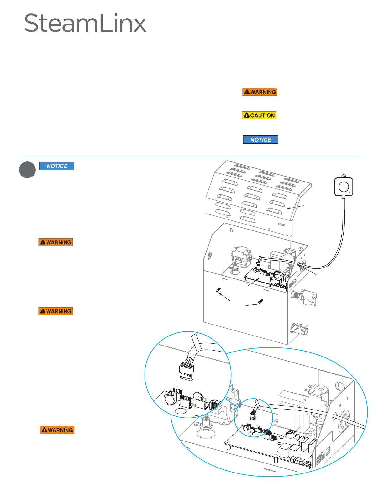
Cover
Screws
Generator
Cover
Knock-out in
the Generator
Jacket
Connecting SteamLinx A to
the Steam Generator
• Disconnect power to the generator
at the breaker box.
• Locate the SteamLinx A
(with the integral cable).
To prevent shock hazard,
disconnect power at the breaker box before
removing generator cover
• Remove knock-out.
• Remove generator cover.
• Route the SteamLinx A cable
through the knockout
ELECTRICAL SHOCK HAZARD.
MrSteam steam generators are connected
to 240V line voltage and contain live
electrical components. All installation and
service must be performed by a
licensed and qualified electrician.
• Locate the circuit board.
• Plug the SteamLinx A into the
white connector located at the
far left side of the circuit board.
• Replace cover and screws.
• Restore power.
ELECTRICAL SHOCK HAZARD.
MrSteam steam generators are connected
to 240V line voltage and contain live
electrical components. All installation and
service must be performed by a licensed
and qualified electrician.
Circuit
Board


