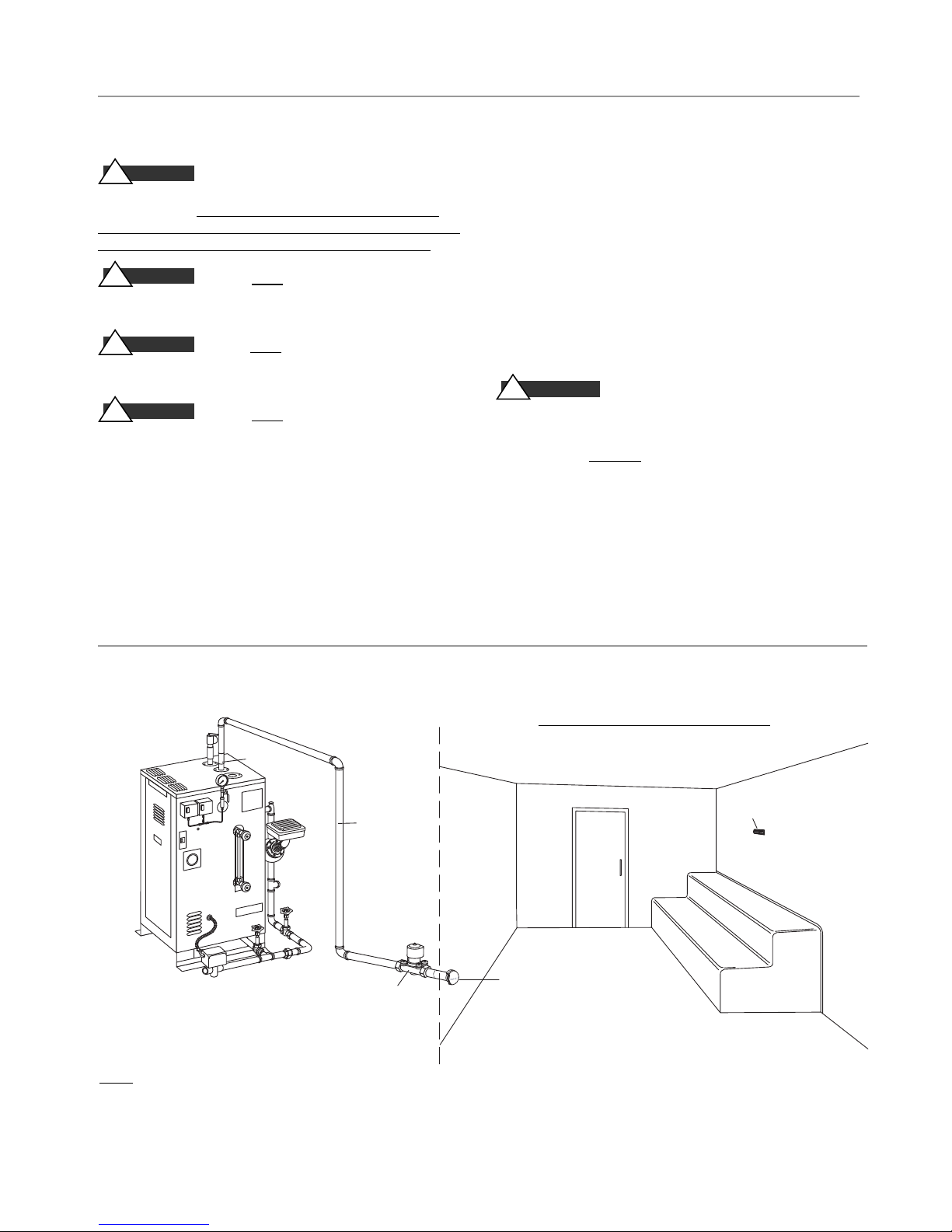
Steam Line
1.
The Digital 1 steam solenoid valve should be plumbed as close as
practical to the steam room using only brass pipe or copper tubing
but should remain accessible for service.
2.
Pitch the steam line a minimum of 1/4”per linear foot of run,
towards the steam outlet on the generator, avoid valleys and trap-
ping of condensate.
3.
Fully insulate steam lines with suitably-rated high temperature
insulation.
4.
Install a suitable strainer or filter between the steam generator and
steam solenoid valve.
5.
Use of unions in plumbing lines is recommended.
Drain
In accordance with Code requirements, provide a drain line
connection from the steambath generator drain valve(s). If an Auto
Blowdown is used, the drain line must be connected to
the automatic blowdown valve. Refer to National and local plumbing
Codes for drain requirements including receptor,
trap, vent requirements and drain lines.
Safety Valve
Where permitted by Code, provide a
connection for safety |valve dis-
charge.
DO NOT
connect a shut off valve or plug at the safety valve outlet.
DO NOT
reduce outlet size of safety valve discharge.
Installation
Plumbing
All plumbing shall be performed by a qualified
licensed plumber and in accordance with applicable
National and local Codes.
Water Supply
1.
Connect to hot or cold water line. A hot water line
is preferable, however incoming hot water should
not exceed 160°F
I PORTANT:
The low temperature setting on many
hot water heaters provides 120°F water
2.
Provide a service shut off valve and water-line
strainer in the water supply line upstream to the
steambath generator
3.
Flush the inlet water line thoroughly before mak-
ing connection to the steambath generator.
4.
Incoming water supply should be at least 25 psig
and is not to exceed 100 psig.
5.
Install a back flow preventor as required by Code.
6.
Provide anti-water hammer device as required in
accordance with Code.
7.
Use of unions in plumbing lines is strongly
recommended.
8.
Recheck all factory and field plumbing connec-
tions for tightness.
mr.steam®CU Series Installation, Operating & Maintenance Manual
6
!WARNING
P I P E S I Z E G U I D E
_____________________
Steam Outlet: 1"
Steam Solenoid Valve:3/4"
Steam Head: 3/4"
Water Quality Information
For optimum results, the feedwater supply should be
tested prior to initial startup. If the mineral content
exceeds the following recommended limits, various
external treatment processes may be used to correct the
problem.
NOTE:
An analysis of the on-site boiler feedwater must
be made by a recognized and reliable water treatment
company to ascertain the existing condition and treat-
ment required.
Recommended Feedwater Quality
Hardness, ppm 8 – 85 (~0.5 – 5 gpg)
P-Alkalinity, ppm 85 – 410 (~5 – 24 gpg)
T. Alkalinity, ppm 200 – 500 (~7 – 0 gpg)
pH (strength of alkalinity) 8.0 – 11.4
Blowdown boiler at least a once a day. If boiler water
or feed-water are outside the above limits, a more
frequent blowdown is required
Recommended Limits Within a Boiler
Total Dissolved Solids, ppm 3500 Sulfite (SO3), ppm 25 – 50
Total Alkalinity, ppm 850 Phosphate, ppm 30 – 60
Suspended solids, ppm 300 P-Alkalinity as CaCO3, ppm 900
Silica (SiO2), ppm 125 Iron, ppm 2
Water quality can affect efficiency or result in boiler damage if neglect-
ed. Boiler feedwater contains impurities in solution and suspension.
These impurities concentrate in the boiler. The concentration of these
impurities increases as more feedwater is introduced into the boiler and
steam is produced. If the suspended solids are allowed to concentrate
beyond certain limits, a deposit or “scale” will form on the boiler
internal surfaces. This deposit can interfere with the proper boiler
operation and cause boiler failure.
The concentration of these impurities is generally controlled by the
feedwater quality and by blowdown. Blowdown refers to removing a
portion of the boiler water with high solids concentration and replac-
ing it with makeup water of a lower concentration.