CV Register Description Range Default
CV1 R1 Short address 1-127 3
CV2 R2 Start voltage 0-32 0
CV3 R3 Acceleration 0-32 0
CV4 R4 Deceleration 0-32 0
CV5 --- Top voltage 0-32 32
CV6 Speed curve select (0=linear, 1=slow
increase, 2=fast increase at slow speed 0-2 0
--- R6 Page number --- ---
CV29 R5 Basic configuration --- 2
CV7 R7 Manufacturer version number --- 32
CV8 R8 Manufacturer ID --- 143
CV17 --- Long address upper byte 192-231 192
CV18 --- Long address lower byte 0-255 3
CV19 --- Advanced consist address 0-127 0
CV49 Sound on/off except horn that is alw ays on 0-1 1
CV50 --- Horn type (34 types) 0-33 4
CV51 --- Horn volume 0-3 3
CV52 --- Bell type (8 types) 0-7 3
CV53 --- Bell volume 0-3 3
CV54 --- Bell ring rate 0-50 3
CV55 --- Diesel rumble volume 0-3 3
CV56 --- Brake squeal volume 0-3 3
CV57 --- Dynamic brake volume 0-3 3
CV58 --- Air release volume 0-3 3
CV59 --- Air pump volume 0-3 3
CV60 --- Safety pop valve volume 0-3 3
CV61 --- Engine cooling fan volume 0-3 3
CV62 --- Coupling volume 0-3 3
CV64 --- Rail wheel clack 0-3 3
CV65 Kick start voltage 0-63 63
CV67-94 28 speed steps table while CV29.4=1 1-255 linear
CV105 --- User identification number 0-255 0
CV106 --- User identification number 0-255 0
CV113 --- Coupling fire volume 0-3 3
CV114 --- Brake release volume 0-3 0
CV115 --- Auto brake squeal enable/disable 0-1 1(enable)
light mode, 0=normal headlight
1=off, dim , bright cycle, 2=rule 17
CV122 --- Notch mode, 0=auto, 3=manual 0-3 0
CV123 Prime m over type (4=diesel off/all other
sounds on) 0-4 2
CV125 --- Programming to "1" will restore some CV's
to factory s ettings --- 0
0CV117 0-2
0CV21 --- When CV21=0, functions follow its ow n address.
CV21=1, functions f ollow the consist address ---
N Gauge DCC/DC Diesel Sound
Decoder with 28 Functions
Item #0001644-2 (Kato SD70 MAC & AC4400)
Thank you for purchasing this MRC DC/DCC Diesel sound
decoder. This dash 2 version has 4 prime mover sounds recorded
directly from the real SD70 and other type of locomotive. All
notching along with increased speeds were also part of the
recording process. Unlike some others, we do not use simply
increase volume or frequency of the prime mover sound to
simulate the notching process. The decoder has presets for all
of its functions, so no adjustments should be required. However
if you wish to make changes, this decoder has a full range of
options
•Digital Signal Process (DSP) and reverb effect
•Built in four types of synchronized diesel prime mover
sounds to choose from
•Built in 34 user selectable different horns and 8 bells
•Lifelike, randomly associated locomotive sounds
•28 accessory functions allowing more sound control
than ever
•Programmable individual sound volumes
•1.0 amp capacity
•Directional headlight and rule 17
•2-digit (1-127) or 4-digit (1-9999) address
•Supports full read back of CV’s
•Programmable start and top voltage
•Programmable acceleration and deceleration rate
•Programmable 14, 28, 128 speed steps
•Supports speed table
•Supports advanced consisting (CV19)
•Supports programming on the main (OPS mode)
•Compatible with NMRA DCC standards
•Built a10mm, 32 ohm speaker
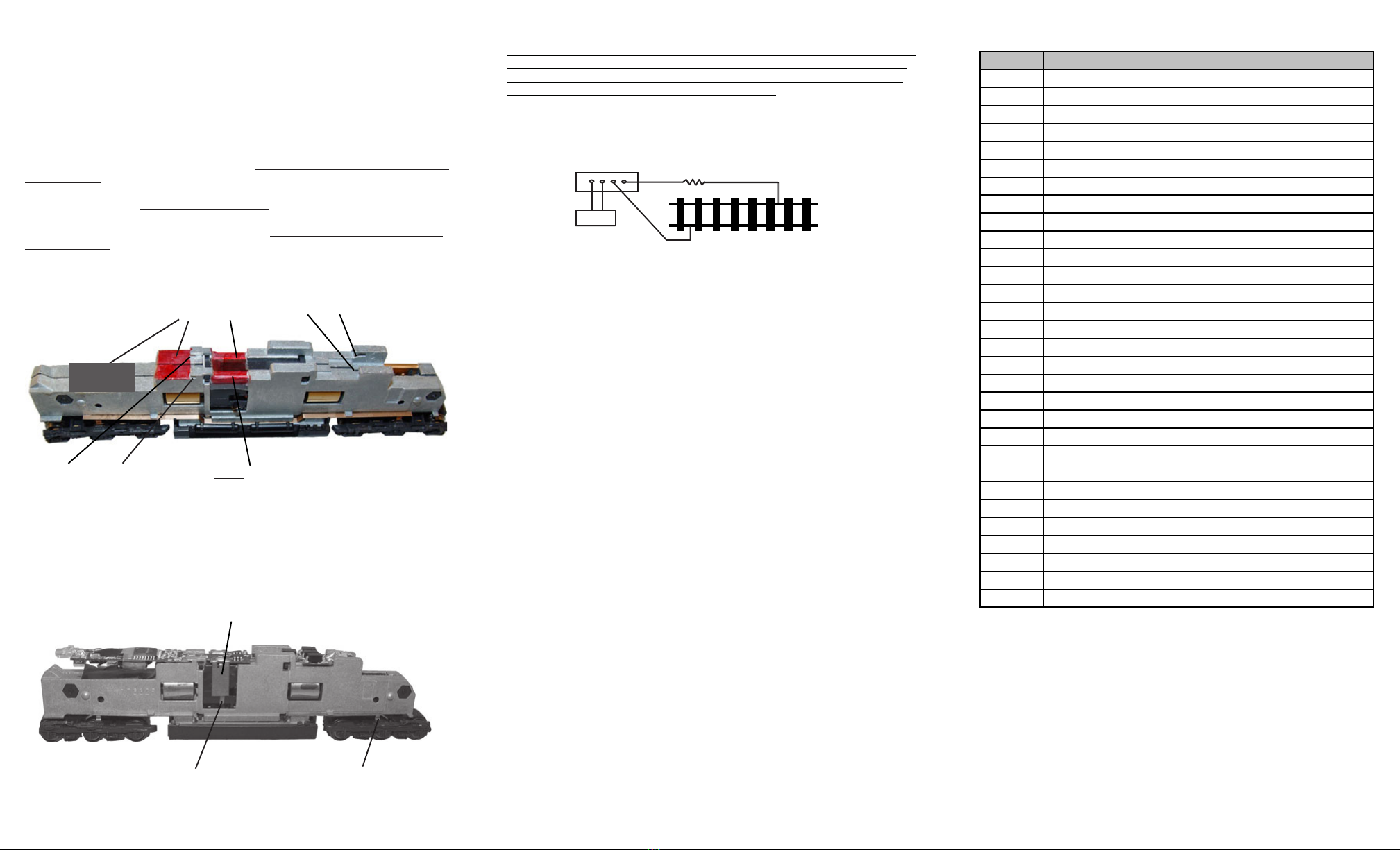
• Directly replaces Kato SD70MAC and AC4400 PC
boards
SPEED TABLE CV67-CV94 FOR 28 SPEED STEPS
When CV29’s bit 4 is set to “1” it will use the speed table formed by CV67-
CV94 to control speed (motor voltage). It allows you to setup each speed for
all 28 speed steps. First, program CV29 to 18 for short addresses (1-127) or
program CV29 to 50 for long addresses (128-9999) to enable speed table
control. Then select throttle to 28 speed steps and run your loco at speed step
1. Use program CV on the main to change CV67’s value (1-255) to adjust step
1’s speed. The kick voltage, CV65 is only applied when the speed step
changes from 0 to 1. You should switch between 0 to 1 many times to check
step 1’s speed. When done with CV67, select speed step 2 and program
CV68. CV68’s value must be greater then CV67’s. When done with CV67-
CV94, use read back CV to make sure their values are in increasing order.
Note: When using MRC Prodigy DCC to program addresses it will automatically
disable the speed table (set CV29’s bit 4 to “0”). Programming CV125 to 1 will
also disable the speed table and re-program CV67-CV94 to a default linear
speed setting.
TROUBLE SHOOTING
Whenever the decoder doesn’t work please use the program track to program
CV# 125 with value 1 to restore the decoder to factory settings. This should
bring the decoder to life with address #3. This decoder should perform well
with all DCC systems. The maximum DCC output should be less than 15 V. If
the locomotive does not respond to commands, it may have lost its address.
Please re-program the address and program CV19 to 0 (disable consist). If it
responds slowly, you should clear its momentum by reprogramming CV3 and
CV4 to zero. If step 1’s speed is too high, you should program start voltage,
CV2 to zero. If its top speed is too slow, program top voltage CV5 to 31. You
should also clean the track to improve electrical pickup. Read your DCC
system manual to learn how to program and operate the decoder. For more
information about registers/CVs and their functions, please refer to the NMRA
DCC Standard & Recommended Practices, RP-9.2.2. This is available directly
from the NMRA or their website at www.nmra.org.
FCC COMPLIANCE
This device complies with part 15 of the FCC rules. Operation is subject to the
following two conditions. (1) This device may not cause harmful interference,
and (2) This device must accept any interference received, including interfer-
ence that cause undesired operation.
RETURN PROCEDURE
This decoder carries a 6 month warranty against factory defects. This
warranty does not include abuse, misuse, neglect, improper installation, or
any modifications made to this decoder, including but not limited to the removal
of the NMRA plug if applicable. If it should become necessary to return the
decoder for warranty repair/replacement, please include a copy of the
original sales receipt. Please include a letter (printed clearly) with your
name, address, daytime phone number, and a detailed description of the
problem you are experiencing. Please also include a check or a money order
for $8.00 to cover return shipping and handling. If the decoder is no longer
considered under warranty, then please include a check or a money order for
$29.00 to cover the cost of repair or replacement and return shipping and
handling. Be certain to return the decoder only. Any questions
regarding Warranty Policy can be directed to our Customer Service
Department by calling 732-225-6360 between the hours of 8:30am and
6:00pm EST, or by emailing: rrtech@modelrectifier.com
Send the decoder to: Model Rectifier Corporation
Attn: Parts & Service
80 Newfield Avenue
Edison, NJ 08837-3817 U.S.A
PROGRAMMING
This decoder supports all program modes and read back features. With MRC
Prodigy Advance DCC you can read its address and CV value.