manuals.online logo
Brands
  1. Home
  2. •
  3. Brands
  4. •
  5. MRC
  6. •
  7. Media Converter
  8. •
  9. MRC AD332 User manual

MRC AD332 User manual

AD332 ‘N’ Gauge Decoder
Congratulations! You have just purchased an an advanced
DCC locomotive decoder. Combined with any DCC System,
our decoder will make your model railroad more realistic
and exciting. Thank you for purchasing MRC products.
•Designed for N scale
•Maximum current: 0.75 amp
•Programmable for either 2-digit (1-127) or 4-digit
(1-9999) addresses
•Programmable start voltage
•Programmable acceleration rate
•Programmable deceleration rate
•Programmable top voltage
•Programmable 14, 28 or 128 speed steps
•Directional lighting control for front and rear
lights at 0.2 amp rate
•Compatible with NMRA DCC standard
•Complies with the Part 15 of FCC
•28.0mm long x 8.5mm wide x 2.5mm high
FCC COMPLIANCE
This device complies with the part 15 of FCC rule. Operation is subject to the following two
conditions. (1) This device may not cause harmful interference, and (2) This device must accept
any interference received, including interference that cause undesired operation.
RETURN PROCEDURE
If it should become necessary to return your decoder, unplug the decoder and return the decoder
only. Please include a letter (printed clearly) with your name, address, a daytime telephone
number, and a detailed description of the problem you are experiencing. Please also include a
$9.00 check for handling and shipping fee. Be certain to return the decoder only.
Send the decoder to:
Model Rectifier Corporation
Attn: Parts & Service
80 Newfield Avenue
Edison, NJ 08837-3817 U.S.A


2003 MODEL RECTIFIER CORPORATION
80 NEWFIELD AVENUE, EDISON NJ 08837-3817
Tel. 732-225-6360
PRINTED IN USA
INS-2273
INSTALLATION
It is quite a challenge to install a decoder into a standard locomotive. You should have some basic
electrical knowledge and soldering skills. If you do not have the above requirements, please ask
the dealer for help in installation.
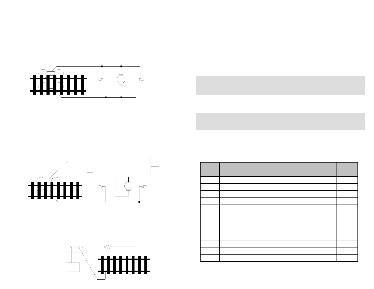
Figure 1 shows the electrical circuit of most standard locomotives. The terminals of the motor and
lights are directly connected to the wheel pick-ups. Each type of loco has its own method of
electrical pick-up and distribution. The connection between the wheels, motor and lights could be
wires, clips, the body or chassis, a PC board or any other type of conductor. Figure out your loco’s
electrical system and how to disconnect (isolate) the motor and lights.
Figure 1. Connection of standard locomotive. Note: The ‘X’ marks indicate where to disconnect
(isolate).
Figure 2 shows you how to wire the decoder. After disconnecting the motor terminals from pick-
ups, connect the red wire to the right side pickup and the black wire to the left side pick up.
Connect the orange wire to the motor terminal that originally connected to the right pickup.
Connect the gray wire to the motor’s other terminal. Connect the front light to the blue wire and the
white wire. Connect the rear light to the blue wire and the yellow wire.
The blue wire is the common terminal for lights. You may use the black wire or the red wire to
replace the blue wire. This is very useful when you find that it is hard to isolate one of the light
terminals from the pickup. Wiring the bulb this way will also make the light dimmer. If your loco has
only a front light, you should connect the white and the yellow wires together.
MAKE A TEST TRACK
Before you start with your decoder installation, we strongly recommend building a test track that
uses a 20-ohm resistor to limit current. Only test your installed decoder on the test track. The
test track will prevent any damage due to an incorrectly wired decoder.
Figure 3. Diagram of test track
TEST
All MRC decoders have been factory programmed with address #3, 28/128 speed steps and
maximum top voltage. After you have finished your decoder installation, you are ready to test it.
Never run the installed decoder on your layout without first passing the test. You may
damage the decoder if it is not wired correctly or if you have not properly isolated the motor and
the lights.
Put the loco on the test track. Select the Run Mode of your DCC system and select or acquire
address #3. Move up throttle and the loco should move forward. Push the light button and the front
light of your loco should turn on. Push the reverse direction button. The loco should move
backward and the rear light should turn on. The loco cannot get normal speed because there is a
20-ohm protection resistor in the test track. If you are able to turn on/off the front and rear lights
and you are able to move the loco forward and reverse, you did a great job. Congratulations! Do
not test the loco on the test track for an extended period of time. To do so will cause the
protection resistor to overheat.
If your installed decoder does not pass the test, find the problem, correct it and test it again.
As long as you test the decoder on the test track there is little chance of damaging your
decoder. This is why making a test track is so important.
PROGRAMMING
The AD332 decoder supports the following register and CV programming.
MRC PRODIGY DCC and MRC Command 2000 users do not need to know all these register/CV
numbers because the MRC DCC systems use model railroading terminology. It is easy to
understand and easy to program.
The MRC AD332 decoder should perform well when used with other brand command systems.
See your DCC command station’s manual to learn how to program and operate the decoder. For
more information about register/CVs and their functions, please refer to the NMRA DCC Standard
& Recommended practices, RP-9.2.2 This is available directly from the NMRA or their website at
www.nmra.org.
Right side pickup
Front
light Motor Rear
light
Left side pickup
X X
X X X
X
Figure 2. AD332 wiring diagram
Front
light Rear
light
Red
OrangeGray
White
Black Yellow
AD332 Decoder
Motor
Blue
DCC base unit
Power supply Test track
20 ohm resistor
CV Register Description Range Factory
Value
CV1 R1 Shortaddress 1-127 3
CV2 R2 Startvoltage 0-32 0
CV3 R3 Acceleration 0-32 0
CV4 R4 Deceleration 0-32 0
CV5 --- Maxvoltage 0-32 0
CV29 R5 Basic configuration --- 2
CV7 R7 Manufacturer version number --- 32
CV8 R8 Manufacturer ID --- 143
CV17 --- Long address upper byte 192-231 192
CV18 --- Long address lower byte 0-255 3
CV19 --- Advanced consist address 1-127 0
--- R6 Page number 0-31 1

Other MRC Media Converter manuals

MRC 0001958 User manual

MRC

MRC 0001958 User manual

MRC 0001806 User manual

MRC

MRC 0001806 User manual

MRC 0001802 User manual

MRC

MRC 0001802 User manual

MRC 0001611 User manual

MRC

MRC 0001611 User manual

MRC 0001812 User manual

MRC

MRC 0001812 User manual

MRC 0001659 User manual

MRC

MRC 0001659 User manual

MRC 0001817 User manual

MRC

MRC 0001817 User manual

MRC SOUNDER 0001665 User manual

MRC

MRC SOUNDER 0001665 User manual

MRC 0001911 User manual

MRC

MRC 0001911 User manual

MRC 0001822 User manual

MRC

MRC 0001822 User manual

MRC 0001800 3 User manual

MRC

MRC 0001800 3 User manual

MRC 0001910 2 User manual

MRC

MRC 0001910 2 User manual

MRC 0001641 User manual

MRC

MRC 0001641 User manual

MRC SOUNDER 0001815 User manual

MRC

MRC SOUNDER 0001815 User manual

MRC Sheer Brilliance 0001638 User manual

MRC

MRC Sheer Brilliance 0001638 User manual

MRC 0001750 User manual

MRC

MRC 0001750 User manual

MRC 0001639 User manual

MRC

MRC 0001639 User manual

MRC 0001808 User manual

MRC

MRC 0001808 User manual

MRC 0001626 User manual

MRC

MRC 0001626 User manual

MRC AD324 User manual

MRC

MRC AD324 User manual

MRC 0001955 User manual

MRC

MRC 0001955 User manual

MRC 0001617 User manual

MRC

MRC 0001617 User manual

MRC 0001803 User manual

MRC

MRC 0001803 User manual

MRC 0001811 User manual

MRC

MRC 0001811 User manual

Popular Media Converter manuals by other brands

Renishaw FORTiS-S FS installation guide

Renishaw

Renishaw FORTiS-S FS installation guide

RME Audio ADI-642 specification

RME Audio

RME Audio ADI-642 specification

Comprehensive CVE-TRX02A user manual

Comprehensive

Comprehensive CVE-TRX02A user manual

Allied Telesis Converteon AT-CV5M01 datasheet

Allied Telesis

Allied Telesis Converteon AT-CV5M01 datasheet

AirStage UTY-VLGX installation manual

AirStage

AirStage UTY-VLGX installation manual

JDS Labs ATOM DAC operating instructions

JDS Labs

JDS Labs ATOM DAC operating instructions

Adaptec VideOh! AVC-2410 Getting started

Adaptec

Adaptec VideOh! AVC-2410 Getting started

LevelOne GVT-2010 quick start guide

LevelOne

LevelOne GVT-2010 quick start guide

syscomtec SCT-UCHD2-KVM manual

syscomtec

syscomtec SCT-UCHD2-KVM manual

QSC Q-SYS NV-32-H Hardware user manual

QSC

QSC Q-SYS NV-32-H Hardware user manual

TRENDnet TFC-110 Quick installation guide

TRENDnet

TRENDnet TFC-110 Quick installation guide

Extron electronics MediaPort 300 Setup guide

Extron electronics

Extron electronics MediaPort 300 Setup guide

Axon Synapse DBD18 Installation and operation manual

Axon

Axon Synapse DBD18 Installation and operation manual

Danfoss iC7 Series installation guide

Danfoss

Danfoss iC7 Series installation guide

Kingrex UC192 user manual

Kingrex

Kingrex UC192 user manual

Thrax Audio Maximinus owner's manual

Thrax Audio

Thrax Audio Maximinus owner's manual

Omnitron Systems Technology Serial RS-422 and RS-485 to Fiber Media Converter... user manual

Omnitron Systems Technology

Omnitron Systems Technology Serial RS-422 and RS-485 to Fiber Media Converter... user manual

Christie Hedra Series installation guide

Christie

Christie Hedra Series installation guide

manuals.online logo
manuals.online logoBrands
  • About & Mission
  • Contact us
  • Privacy Policy
  • Terms and Conditions

Copyright 2025 Manuals.Online. All Rights Reserved.