manuals.online logo
Brands
  1. Home
  2. •
  3. Brands
  4. •
  5. MRC
  6. •
  7. Media Converter
  8. •
  9. MRC AD322 User manual

MRC AD322 User manual

AD322 “G” Gauge
Diesel Sound Decoder
with MRC Light Effects
Thank you for purchasing our highly advanced DCC locomotive
decoder. Combined with any DCC System, our decoder will
make your model railroad more realistic and exciting.
•8 amp capacity, 3 accessory functions at 0.1 amp
rate (F1 – F3)
•4 sound functions, (bell, long horn, short horn,
uncoupling), plus diesel idle and diesel rumble
•Programmable for either 2-digit (1-127) or
4-digit (1-9999) addresses
•Programmable start voltage
•Programmable acceleration rate
•Programmable deceleration rate
•Programmable top voltage
•Programmable 14, 28, 128 speed steps
•Directional lighting control for front and rear lights
at 0.2 amp rate
•Supports advanced consisting (CV19)
•Supports programming on the main
•Compatible with NMRADCC standard
•Complies with the part 15 of FCC
•2 wired quick disconnect plugs for easy decoder
installation
•2 inch speaker included
•Dimensions: 36mm x 88mm x 23mm
•Suitable for either 1 motor or 2 motor locomotives
The MRC AD322 decoder should perform well when used with other brand
command systems. See your DCC command station’s manual to learn how to
program and operate the decoder. For more information about register/CVs and
their functions, please refer to the NMRA DCC Standard & Recommended prac-
tices, RP-9.2.2 This is available directly from the NMRA or their website at
www.nmra.org.
FCC COMPLIANCE
This device complies with the part 15 of FCC rule. Operation is subject to the
following two conditions. (1) This device may not cause harmful interference, and
(2) This device must accept any interference received, including interference that
cause undesired operation.
RETURN PROCEDURE
If it should become necessary to return your decoder, unplug the decoder and
return the decoder only. Please include a letter (printed clearly) with your name,
address, a daytime telephone number, and a detailed description of the problem
you are experiencing. Please also include a $15.00 check for handling and shipping
fee. Be certain to return the decoder only.
Send the decoder to:
Model Rectifier Corporation
Attn: Parts & Service
80 Newfield Avenue
Edison, NJ 08837-3817 U.S.A


2003 MODEL RECTIFIER CORPORATION
80 NEWFIELD AVENUE
EDISON NJ 08837-3817
Tel. 732-225-6360
PRINTED IN CHINA
INS-2269
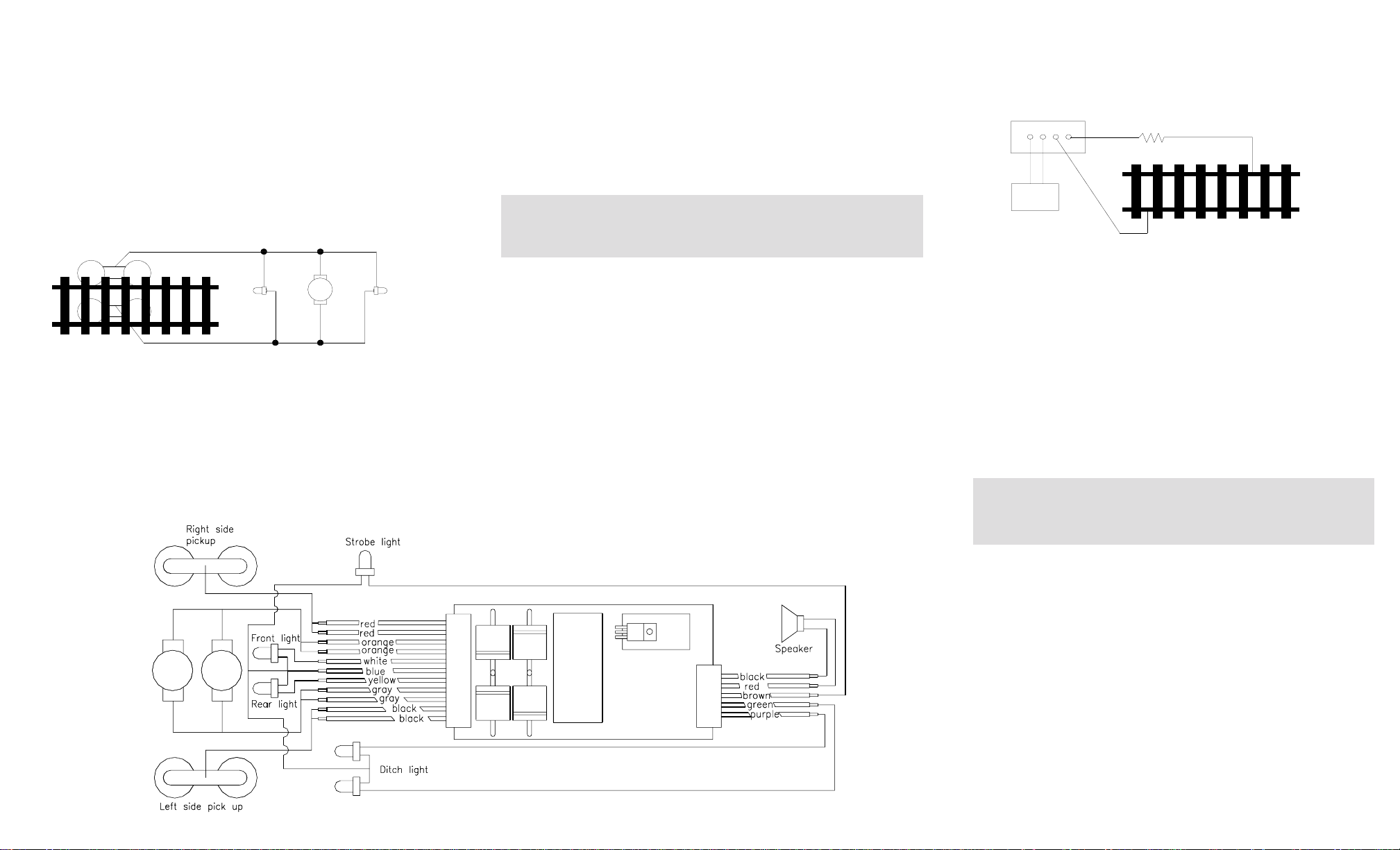
2. MRC Light Effects:
A.“Rule 17” directional headlights: Headlights on/off, (F0), light button. One
light is bright to indicate direction of travel and the other is dim. Also in
this mode, the (F0) light button turns on the strobe light if hooked up.
Normal headlight wiring is used for “Rule 17” lighting (white, yellow & blue
common wire).
B.Ditch lights: Use of the long horn (F2) or short horn (F3) buttons will
activate ditch lights with horn sounds. Ditch lights will flash 5 times after
horn sound ceases. If your DCC system has an F5 button, you can use it
to turn ditch lights steady on/off. Otherwise you must use the uncoupling
button (F4) to turn ditch lights steady on/off. When horn is activated, the
ditch lights will flash. To wire ditch lights, use green and purple accessory
wires with blue (headlight) common wire.
C.Strobe light: This light simulates the rooftop strobe light on some
locomotives. In the MRC Light Effects mode, the strobe will flash when
“Rule 17” headlights are on regardless of loco direction. To wire strobe
light, use brown accessory wire with blue (headlight) common wire.
When hooking up accessory lighting, regardless of mode being used,
use light bulbs rated at maximum track power. The bulbs receive full
track power when the functions are activated. Auxiliary factory
installed locomotive lighting that use LEDs or 1.5-volt bulbs will need
a resistor placed in line to prevent them from burning out.
HOW TO SELECT THE MRC LIGHT EFFECTS
The AD322 is shipped from the factory in the normal/default mode (address #3)
normal lights & functions. There are two ways to access the MRC Light Effects:
1. The MRC EZ way (for all DCC systems except the MRC Command 2000):
Place your locomotive on a programming track. Program your locomotive to
address #1. This step turns our MRC Light Effects on. Final step: Now
program in your locomotive running address, either 2 or 4 digit, and adjust
the rest of your running parameters (momentum, start voltage, etc). That’s
it! To turn off the MRC Light Effects, simply program the locomotive to
address #3 and then follow the final step above.
You cannot run a locomotive on address #1 and retain normal lights/
function or run a locomotive on address #3 with MRC Light Effects.
These two addresses are reserved for turning the functions on and off,
but a locomotive will still be able to run on these addresses.
2. The other way:
If your non-MRC DCC system has the ability to program CVs, you can go
directly to CV 64 to turn on your MRC Light Effects. You can use the
register/ CV chart we have provided for you in this instruction booklet or visit
the National Model Railroad Association website at www.nmra.org for a
more comprehensive understanding of CVs and registers.
PROGRAMMING
The AD322 decoder supports the following register and CV programming.
MRC PRODIGY DCC and MRC Command 2000 users do not need to
know all these register/CV numbers because the MRC DCC systems use
model railroading terminology. It is easy to understand and easy to
program.
CV Register Description Range Factory
Value
CV1 R1 Shortaddress 1-127 3
CV2 R2 Start voltage 0-32 0
CV3 R3 Acceleration 0-32 0
CV4 R4 Deceleration 0-32 0
CV5 --- Maxvoltage 0-32 0
CV29 R5 Basic configuration --- 2
CV7 R7 Manufacturer version number --- 32
CV8 R8 Manufacturer ID --- 143
CV17 --- Long address upper byte 192-231 192
CV18 --- Long address lower byte 0-255 3
CV19 --- Advanced consistaddress 1-127 0
CV64 ---
Light effect setting
(0=special light effect/1=normal light effect) 0-1 1
CV105 --- User identifier number 0-255 0
CV106 --- User identifier number 0-255 0
--- R6 Page number 0-31 1
Figure 2 shows you how to wire the decoder. After disconnecting the motor
terminals from pick-ups, connect the red wire to the right side pickup and the black
wire to the left side pick up. Connect the orange wire to the motor terminal that
originally connects to the right pickup. Connect the gray wire to the motor’s other
terminal. Connect the front light to the blue wire and the white wire. Connect the
rear light to the blue wire and the yellow wire.
The blue wire is the common terminal for lights and accessory functions. You may
use the black wire or the red wire to replace the blue wire. This is very useful when
you find that it is hard to isolate one of the light terminals from the pickup. Wiring
the bulb this way will also make the light dimmer. If your loco has only a front light,
you should connect the white and the yellow wires together.
Smoke units draw a lot of current! If your locomotive comes equipped with a
smoke unit, do not attempt to power it off any of the decoder functions. Wire it
directly to the wheel pick-ups for constant smoke emission.
SPEAKER PLACEMENT
Your AD322 G scale diesel sound decoder comes with a 2" speaker rated at
8 ohms. Placement of the speaker is up to you, usually installed in loco fuel tank or
inside top of body shell. Some manufactures have pre-drilled speaker holes
somewhere in the loco to aid in placement of the speaker. Also some locos come
with a speaker installed. You can use this pre-installed speaker as long as it is rated
at 8 ohms.
Use hot glue to affix the speaker to the locomotive. It is also recommended that a
baffle be built around the speaker if space permits to obtain a fuller sound.
Place speaker onto body/fuel tank, applying hot glue around rim to affix. Place
baffle or sound tube over speaker and affix the wire speaker to decoder with hot
glue.
MAKE A TEST TRACK
Before you start with your decoder installation, we strongly recommend
building a test track that uses a 20-ohm resistor to limit current. Only test your
installed decoder on the test track. The test track will prevent any damage due
to an incorrectly wired decoder. Figure 3. Diagram of test track
TEST
All MRC decoders have been factory programmed with address #3, 28/128
speed steps and maximum top voltage. After you have finished your decoder
installation, you are ready to test it. Never run the installed decoder on your
layout without first passing the test. You may damage the decoder if it is not
wired correctly or if you have not properly isolated the motor and the lights.
Put the loco on the test track. Select the Run Mode of your DCC system and
select or acquire address #3. Move up throttle and the loco should move
forward. Push the light button and the front light of your loco should turn on.
Push the reverse direction button. The loco should move backward and the
rear light should turn on. The loco cannot get normal speed because there is a
20-ohm protection resistor in the test track. If you are able to turn on/off the
front and rear lights and you are able to move the loco forward and reverse,
you did a great job. Congratulations! Do not test the loco on the test track
for an extended period of time. To do so will cause the protection resistor
to overheat.
If your installed decoder does not pass the test, find the problem, correct it
and test it again. As long as you test the decoder on the test track there is
little chance of damaging your decoder. This is why making a test track is
so important.
OPERATION
The AD322 decoder can be operated with diesel idle and rumble turned on or
off. If your DCC system has an F8 button, you can use it to activate the engine
sound. Otherwise you must double click your headlight button (F0) to turn the
diesel idle rumble on or off. When the diesel idle and rumble are turned off,
your bell, long horn, short horn and uncoupling sounds can still be activated by
using the appropriate function buttons (F1-F4).
The sounds of the AD322 are also active regardless of which mode you program
the decoder to: (Normal light/functions mode or MRC Light Effects mode).
The AD322 decoder can be operated in either one of two ways:
1. Normal light/functions:
Headlights are directional and are controlled by your DCC system’s light
button (F0). Decoder functions (accessory lights) are normal on/off
controlled by F1-F3 buttons. Sounds will also be activated at the same time
with the pressing of these buttons.
INSTALLATION
It is quite a challenge to install a decoder into a “G” scale 2 motor locomotive. You
should have some basic electrical knowledge and soldering skills. If you do not
have the above requirements, please ask the dealer for help in installation.
Figure 1 shows the electrical circuit of most standard locomotives. The terminals of
the motor(s), light(s) and smoke unit are directly connected to the wheel pick-ups.
Each type of loco has its own method of electrical pick-up and distribution. The
connection between the wheels, motor(s), light(s) and smoke unit could be wires,
clips, the body or chassis, a PC board or any other type of conductor. Figure out
your loco’s electrical system and how to disconnect (isolate) the motor(s), light(s)
and smoke unit.
Figure 1. Connection of standard locomotive. Note: The ‘X’ marks indicate
where to disconnect (isolate).
The decoder will be inserted between the wheel pick-ups and the motor(s). The ‘X’
marks in Figure 1 show you where to disconnect (isolate). Please observe the
polarity of both motors in dual motored locomotives so both motors operate in the
same direction.
The G scale decoder has 2 sets of red wires, black wires, orange wires and gray
wires to make the wiring of your dual motored locomotive easier. You could use just
one of each color or both, depending upon which is easier for you.
Right side pickup
Front
light Motor Rear
light
Left side pickup
X X
X X X
X
Figure 2. AD322 wiring diagram
DCC base unit
Power supply
Test track
20 ohm resistor

Other MRC Media Converter manuals

MRC 0001922 User manual

MRC

MRC 0001922 User manual

MRC 0001960 User manual

MRC

MRC 0001960 User manual

MRC 0001819 User manual

MRC

MRC 0001819 User manual

MRC 0001952 User manual

MRC

MRC 0001952 User manual

MRC 1651 User manual

MRC

MRC 1651 User manual

MRC 0001644-2 User manual

MRC

MRC 0001644-2 User manual

MRC 0001906 User manual

MRC

MRC 0001906 User manual

MRC 0001611 User manual

MRC

MRC 0001611 User manual

MRC RSW-914 User manual

MRC

MRC RSW-914 User manual

MRC 0001639 User manual

MRC

MRC 0001639 User manual

MRC 0001811 User manual

MRC

MRC 0001811 User manual

MRC 0001820 User manual

MRC

MRC 0001820 User manual

MRC 1651 User manual

MRC

MRC 1651 User manual

MRC Sheer Brilliance 0001637 User manual

MRC

MRC Sheer Brilliance 0001637 User manual

MRC SOUNDER 0001666 User manual

MRC

MRC SOUNDER 0001666 User manual

MRC 0001818 User manual

MRC

MRC 0001818 User manual

MRC AD370 User manual

MRC

MRC AD370 User manual

MRC 0001634 User manual

MRC

MRC 0001634 User manual

MRC 0001808 User manual

MRC

MRC 0001808 User manual

MRC 0001922 User manual

MRC

MRC 0001922 User manual

MRC 0001805 User manual

MRC

MRC 0001805 User manual

MRC 0001711 User manual

MRC

MRC 0001711 User manual

MRC 0001959 User manual

MRC

MRC 0001959 User manual

MRC 0001659 User manual

MRC

MRC 0001659 User manual

Popular Media Converter manuals by other brands

Kiloview D300 Series user manual

Kiloview

Kiloview D300 Series user manual

Omnitron Systems Technology FlexPoint TR User instructions

Omnitron Systems Technology

Omnitron Systems Technology FlexPoint TR User instructions

Granvue MMIO EMB-HDSDI user manual

Granvue

Granvue MMIO EMB-HDSDI user manual

Mylaps ProChip Smart Decoder manual

Mylaps

Mylaps ProChip Smart Decoder manual

TRENDnet TU-S9 user guide

TRENDnet

TRENDnet TU-S9 user guide

Antelope Zodiac Gold owner's manual

Antelope

Antelope Zodiac Gold owner's manual

Audio Authority BlueBeam C-1071A quick start guide

Audio Authority

Audio Authority BlueBeam C-1071A quick start guide

LINK-MI LM-DVI-116B user manual

LINK-MI

LINK-MI LM-DVI-116B user manual

RODCRAFT RC5625 Operator's manual

RODCRAFT

RODCRAFT RC5625 Operator's manual

AMAV CVB4 Installation and operation manual

AMAV

AMAV CVB4 Installation and operation manual

CTC Union IMC-100-PH12 Quick installation guide

CTC Union

CTC Union IMC-100-PH12 Quick installation guide

MyTek Brooklyn Bridge II Roon Core owner's manual

MyTek

MyTek Brooklyn Bridge II Roon Core owner's manual

Theta Digital Generation VIII Series 3 owner's manual

Theta Digital

Theta Digital Generation VIII Series 3 owner's manual

Lindy SCART to HDMI 1.3 HD Scaler user guide

Lindy

Lindy SCART to HDMI 1.3 HD Scaler user guide

Aurora Multimedia DIDO Jr. installation manual

Aurora Multimedia

Aurora Multimedia DIDO Jr. installation manual

Velleman VGA2HDMI user manual

Velleman

Velleman VGA2HDMI user manual

HEIDENHAIN QUADRA-CHEK 100 operating instructions

HEIDENHAIN

HEIDENHAIN QUADRA-CHEK 100 operating instructions

ARRI LCUBE CUB-1 user manual

ARRI

ARRI LCUBE CUB-1 user manual

manuals.online logo
manuals.online logoBrands
  • About & Mission
  • Contact us
  • Privacy Policy
  • Terms and Conditions

Copyright 2025 Manuals.Online. All Rights Reserved.