mrclab PGI-850H User manual

- 2 -
CONTENTS
1.Name Plate Power ……………………4
2.Instruction Manual …………………5
2.1 POWER…………………………5
2.2Temp. Control Operation …………………6
3.2-1 Temp. Setting …………………7
3.2-2.……………………8
2.3 Timer Control Operation…………………9
3.3-1 Temp Timer Setting
3.3-2 Lamp Timer Setting
2.4 Over heat/low warning lamp …………9
3.Trouble shooting for temperature controller …10
4.Maintenace & Cleaning …………11
5.Warranty Card …………12

- 3 -
1.Panel Key Description
1.1 Main Power Switch: Turn on/off main power
1.2 Cooling switch :Turn on to start compressor
1.3 Temp Timer Switch:Turn on/off Temperature Timer
1.4 Lamp Timer Switch: Turn on/off the lamp Timer
1.5 Day/Night Temp. Control :Display setting and
actual temperature for day or night
1.6 Humidity : Display setting and actual humidity
1.7Humidity Power: Turn on/off Humidity
1.8 Over heat alarm lamp and knob

- 4 -
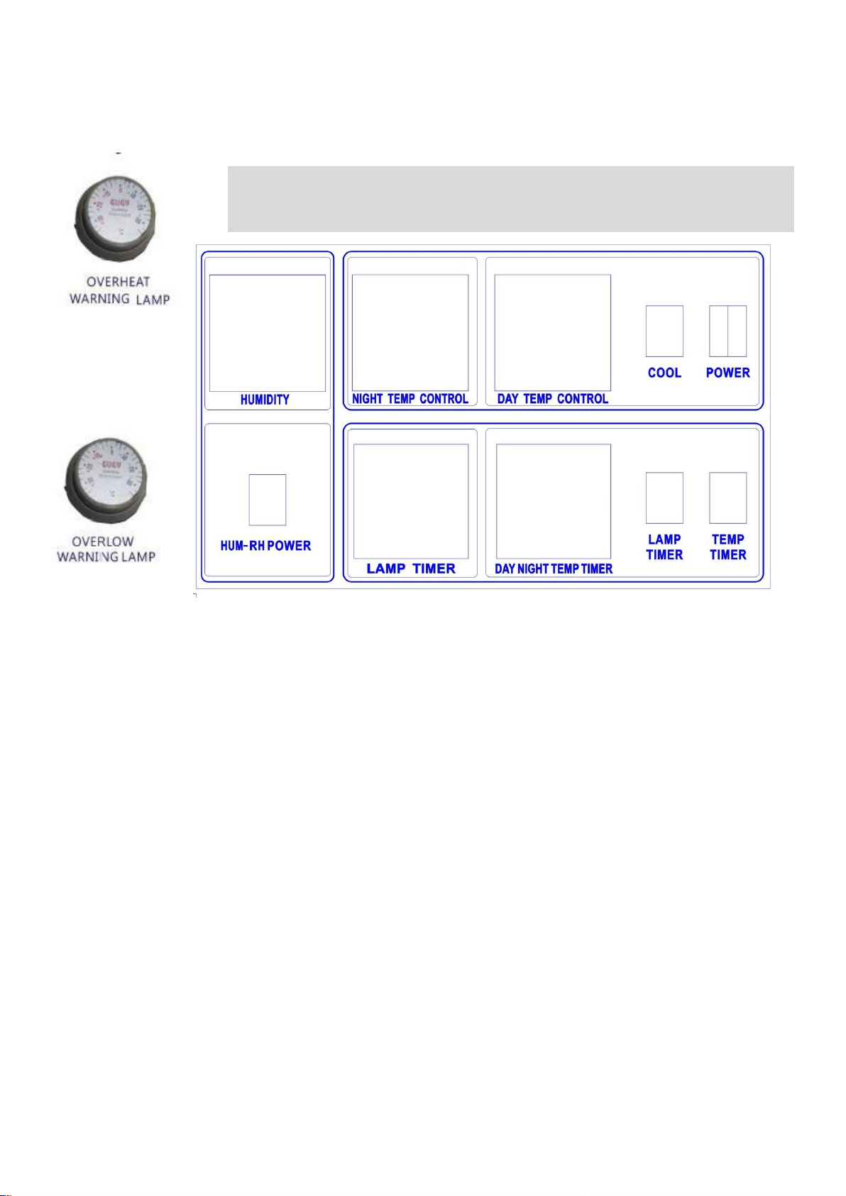
1.9 Over low alarm lamp and knob
2.Operation Manual
1. POWER
1.1 Check the working voltage is □110V/60Hz or □220/50Hz
1.2 After confirming the working voltage is correct, insert the power cord to socket
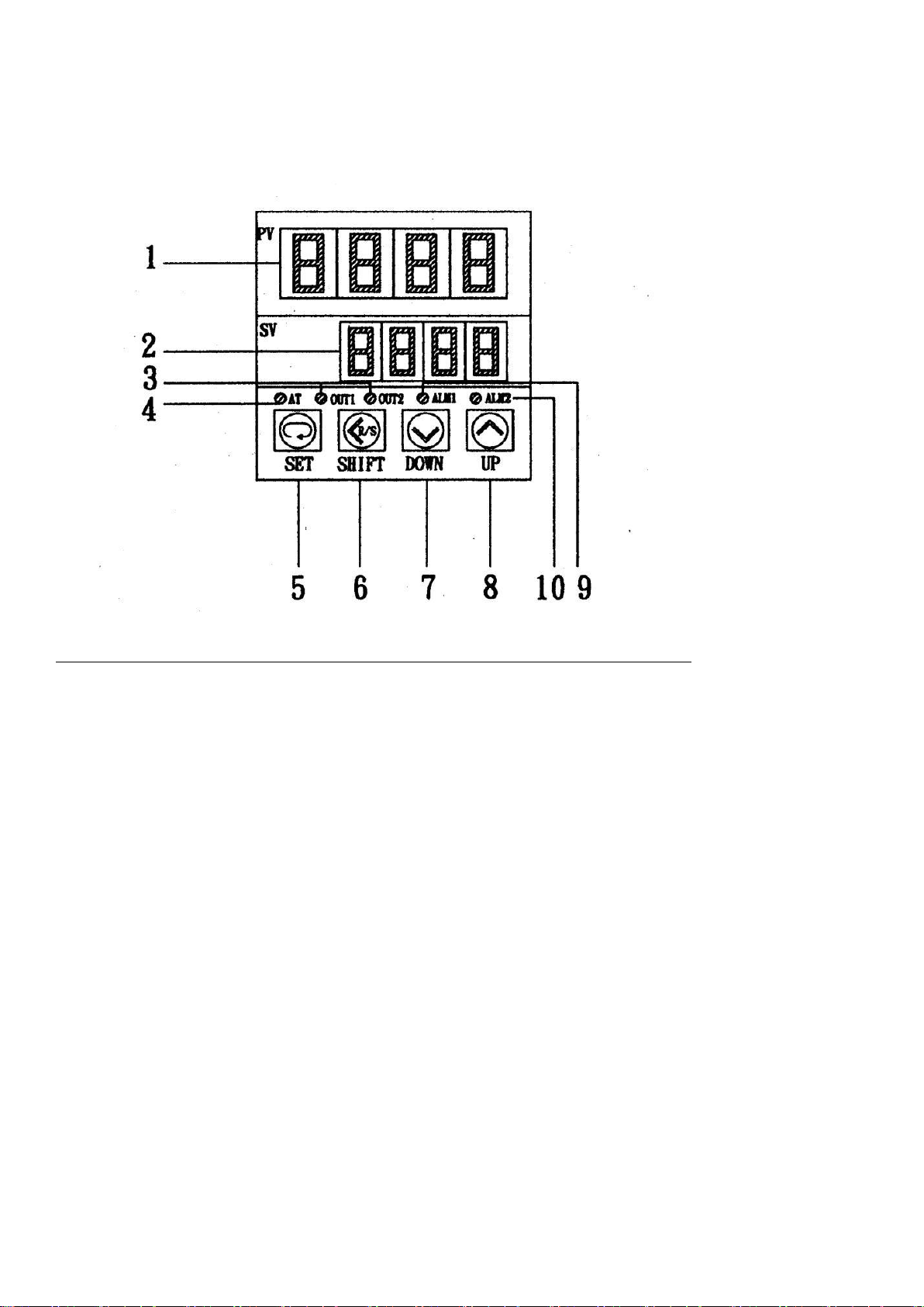
1.3 Turn on the power, the present temperature will display on the temperature control; PV is the
actual temperature of inner box; SV is the set temperature
1.4 Humidity
1.5 Turn on the DEFROST switch at the upper right side of the incubator.
2. COOLER r
Auto. Time-delay 6-7 min. compressor running, every 6 hour automatically power cut to eliminate
mildrew For 6 min. then re-start.(if over low protection start to bounce back, accompanying with alarm
at the same time, after that, automatically delay for 6 min. then re-start running.
3. DAY TEMPERATURE CONTROL
3.1 Setting temperature : First to press the key of “<”, the “SV” key will be in flashing, then start to set
the temperature. The monitor of “SV” will be in high light, then set the required temperature at the
position of high light. To press the key of shift left “►”, the position of high light will be moved
accordingly.
3.2 To press the key of shift up “▲”, the temperature will go up;
To press the key of shift down “▼”, the temperature will go down
3.3 When complete the temperature setting, the “SV” key is still in flashing, need to press the key of
“SET” again, the setting temperature will be on the “SV”
(“PV”) is the actual temperature .
3.4.The heating light of “ Out” is in light , it means the machine is in heating , the light of “OUT” in flash
mean it arrives the required temperature and is normal condition .
4. HUMIDITY CONTROL
Check water bath having water or not , then automatically refill water , setting humidity.Please use RO
water or distilled water

- 5 -
Micro-Computer Controller board for Tem. & Humidity:
1. PV:
Instruction Temp. Light for inside chamber.
2. SV:
Temperature setting.
3. OUT:
Output controller signal light.
4. AT:
Micro-auto calculate function light
5. SET:
Change setting parameter.
6. SHIFT:
Change column for setting Temp. or RH.
(Hundred digit, Ten digit, units digit and decimal point)
7. DOWN:
Set down temp.
8. UP:
Set upper temp.
9. AL1:
High temp. warming alarm light
10. AL2:
Low temp. warming alarm light.

- 6 -
□ TEMP. □HUMIDITY CONTROL OPERATION
1. Turn on POWER switch (110V or 220V 50/60Hz):
Operation:
1. Press SET button and SV light will be flashed
2. Shift (Use up▲ or down▼ to set temp.)
3. Press SET button when temp. setting complete
4. The machine will begin to run the SV temp.
2. ALM1 : High temp. warming alarm (AL1)
Operation:
1. Press SET button after 5 seconds, the AL1 will show on
PV column.
2. Set high temp. warming degree (Use up▲ or down▼)
3. Press SET button again after 5 seconds then return to
original setting (PV).
4. (Using added number on PV to set the high temp. warm
alarm)
Example:
Set PV to 37℃, AL1 set 1℃, when the temp. become 38℃, the
Temp. warming alarm will be on and locked the temp. on
38℃ to protect overheat.
(37℃+1℃=38℃ PV +Protecting degree=AL1
3ALM2: Low temp. warming alarm. (AL2)
Operation:
Example:
1. Press SET button after 5 seconds, the AL1 will show on
the PV, press SET again and AL2 will be showed.
2. Set protecting low temp. alarm degree on SV column
(Use up▲ or down▼)
3. Press SET button again to return original PV.
4. Using deduct number on PV to set the low temp.
warming alarm)
Set PV to 20℃, AL2 setting -1℃, the warming alarm will
be on when the temp become 19℃ and will be locked the
temp. on 19℃ to avoid the machine be auto-off when the
temp. over low. (20℃-1℃=19℃ PV-Warming degree=
AL2)

- 7 -
3. AT: automatic perform pre-setting data.
(You may use this function when the temp. is
unstable or with big temp. difference)
Operation:
1. Press SET after 5 seconds and show AL1 or
AL2.
2. Press SET again and show ∩
「∪symbol.
3. Press ▲up and key in 0001 at SV
4. Press SET and will start to perform, (The
AT light will be on and means it’s working, the
light will be off when it finishes.
5. If you want to stop when it’s working, you may
key in 0000 at SV column when PV column
shows ∩
「∪ symbol, or just turn off the
power and restart.
6. If you are using wider range of
temperature, please record the parameter
value of “ P ”, “ I ”, “D”…etc. could save
your time and key in data directly to use it
again.
□TEMP. □HUMIDITY REVISED VALUE
INSTRUTION
1. Press SET after 5 seconds and into the first
parameter,
2. When it shows ALL value then press SET again and will
show ATU until it shows the value of pb.
3. Use ▲or ▼to adjust. After adjust, press SET again
and wait for 5 seconds, it will return to the original
situation again.
4. Or just wait for 30 seconds it will return to the
original setting.
Example:
Actually temp. 37.1℃, display on 37℃, pb value
add 0.1

- 8 -
Actually temp. 37℃, display on 36.9℃, pb value
deduct 0.1
Notice: Please do not change any parameter value to
avoid affected the machine function.
4.NIGHT TEMPERATURE CONTROL
If you want to use this function of “DAY NIGHT TEMPERATURE TIMER” at
the same time, please turn on the function of “TEMP.TIME SWITCH” first,
then turn the function of “DAY NIGHT TEMPERATURE TIMER” by hand
operation and set the required time, finally, to set up the temperature of the
function of “DAY NIGHT TEMPERATURE CONTROL
5. OVER HEAT CONTROL
The knob is for over heat control. Generally, it is set from 5~10oC. The
indicator will light when the temperature is higher than the set temperature,
will power off automatically to avoid damage to the machine. It will heat
automatically when the temperature is dropped to the original set-point.
6. OVER LOW CONTROL
Regarding the setting of the “OVER LOW CONTROL”, it generally is set at a
temperature lower than 5~10oC. When the temperature is lower than the set
temperature, the indicator will light and will power off automatically the
compressor. Will start the compressor automatically when the temperature is
rose to the original set-point.
7.DAY NIGHT TEMPERATURE TIMER
It could set temperature for 24 hour (day and night). When a set time comes
to the “TEMP.CONTROL”, it will heat and cool automatically.
How to set up: to turn on the timer switch and adjust the clock to the present
time. There are three sections of the meter switch, the upper one is the
nighttime temperature, the down one is the daytime temperature and the
middle (AUTO) is the automatic timing.
If you want to use the daytime and nighttime at the same time (or for the

- 9 -
9. Over Heat Alarm Light
a.Setting overheat temp(Suggest setting temp:+5deg)
b.When the actual temp higher than the setting temp the alarm light will be on and cut off
the main power .
10. Over Low Alarm Light
a.Setting overlow temp ( Suggest setting temp: -5 deg)
b.When the actual temp lover than the setting temp. the alarm light is on and cut off the
compressor
11.HUMIDITY POWER
12.Timer Control
1:Temperatuer Timer
A.Setting the temperature than turn on the temp. timer switch
B.Adjust the timer’s time first(Adjust the indicator with the finger to the present
Time )
C.Turn the control axis in direction of arrow by one notch,(one notch equal fifteen minute ) the
control axis to outside is change to night temp, to inside is change to day temp .
2. Lamp Timer :Same as Temperature timer
Please see below for time switch’s manual
different temperatures), you can chose the “AUTO” timing position, dialing out
the red area of the required nighttime and dialing inward the daytime, then
complete the setting
8.LAMP TIMER
The “LIGHT TIMER” could be set for 24 house day and night lighting time
according to the required time.
How to set up : To turn on the “LIGTH TIMER” switch and adjust the clock to
the present time., There are two sections of the meter switch, the “ON” means
it is under the power on position, if you choose the “AUTO” timing position,
dialing inward the required time then it will light up, dialing out the required
time then it will turn off the light

- 10 -

- 11 -

- 12 -
3.Troubleshooting
Temp. Control System troubleshooting
Conditions
Cause
Solutions
Switch on power, indication light
doesn’t light
a. no current input
b. loose socket
c. unstable voltage input
d. fuse bounce
e. switch indication light
doesn’tlight
f. power cord broken or poor
connection
a. check power supply system
b. plug firmly or replace socket
c. check power, stop using
d. check voltage ,resect
e. replace switch
f. repace power cord
Heat after setting indication light
(Out light)no light
a. internal chamber actual temp.
higher than setting temp.
b. PT platinum damage
c. thermal meter output
message…no
a. wait for heat down or cooling
b. Replace
c. ask for repair & maintenance
Heat light on but temp unable to go
up( AL1)
a. heat wire broken
b. heater loop not good
c. control circuit not good
d. overheat protection set&lock
e. float ball water lever
insufficient (if with water bath)
a. ask for repair & maintenance
b. ask for repair & maintenance
c. ask for repair & maintenance
d. reset
e. fill water
Heat light on but temp unable to go
up
a. Temp. controller out of
control
b. heat loop out of control
c. P、I、Dvalue inaccurate
d. S.S.R. short circuit
a. ask for repair & maintenance
b. ask for repair & maintenance
c. Re-auto calculation
d. ask for repair & maintenanc

- 13 -
Temperature tolerance is large
a. Temperature is unstable
b. P、I、D value is not set or not
correct
c. Temperature is setting is too
close to room temperature
d. circulating fan or motor
cannot work
e. PT platinum bad connection
f. Air circulation inside is
blocked
a. suspend for 30 minus
b. Re-calculating AT
automatically
c. Add cooling system or dropping
ambient temperature e
d. ask for repair
e. ask for repair
f. improve article placement
H U M I D I T Y C O N T R O L S Y S T E M T R O U B L E S H O O T I N G
PLEASE USE RO WATER OR DISTILLED WATER
Condition
Cause
Solution
Switch on power,
Indication light does
not light
a. no current input
b. loose socket
c. unstable voltage input
d. fuse bounce
e. switch indicated light doesn’t light
f. power cord broken or poor contact
a. check power supply system
b. plug firmly or replace socket
c. check power, stop using
d. check voltage, reset
e. replace switch
e. replace power cord
After humidity
setting, humidity
light doesn’t light
(OUT light)
a. internal actual humidity higher than setting
humidity
b. un-act humidity or transformer break
c. humidity meter output message..no
a. await reduce humidity,
cooing, deforst
b. ask for repair & maintenance
c. ask for repair & maintenance
Heat lights, but
humidity unable to
go up
a. shaking plate damage or aging (consumables)
b. heat loop not good, fuse burn out
c. control circuit not good, air motor damage
a. ask for repair & maintenance b.
ask for repair & maintenance
c. ask for repair & maintenance

- 14 -
The cooling system trouble shooting
Condition
Cause
Solution
User can not lower
temperature (Only
happen to the
machine with
cooler)
a. Heat Sink is covered by the dust,
cooling system is not well-running
b. The compressor does not work
c. Spread-Heat-Motor can not work.
d. Compressor run idle, cold media running
a. remove dust, clean &
maintenance
b. Power on failure because of
Power-On-Voltage shortage;
please do not use until it is
improved.
c. Replace Spread-Heat-Motor
d. Ask for repair &
(electric AL1)
d. over humidity setting, lock (electric type)
e. no water, float water lever insufficient
f. water bath not deep
d. reset
e. fill water
f. clean & maintenance
Humidity going up
out of control
a. humidity control, output signal break
b. humidity loop out of control
c. P、I、Dvalue inaccurate or compressor stop
d. TRIAC or RY damage
e. SENSOR damage
a. ask for repair & maintenance
b. ask for repair & maintenance c.
re-auto. tuning, check if
compressor stop, if yes, repair
d. ask for repair & maintenance
e. ask for repair & maintenance
Humidity deviation
large or unable reach
a. humidity unstable yet
b. P、I、Dvalue not set(electric type)
or value inaccurate
c. compressor start abnormally
d. setting value and mechanical function does not
comply
e. circulation fan or motor do not work
f. SENSOR damage
g. internal wind circulation jam
h. refrigerated system frost cause bad circulation
a. observation
b. re-auto. tuning AT or adjust
c. ask for repair & maintenance
d. check machine function, reset
e. ask for repair & maintenance
f. ask for repair & maintenance
g. improve install place
h. defrost
Humidity display
abnormal
a. humidity controller damage
b. SENSOR damage
c. Humidity transformer signal poor
d. Temp. SENSOR not maintenance or aging
a. ask for repair & maintenance
b. ask for repair & maintenance
c. ask for repair & maintenance
d. maintenance or replace

- 15 -
off
e. The ambient temperature is too high to
spread the heat badly, or it is under
closed room / direct sunlight
f. While time-delay starting, the TIMER
does not work.
g. Cooling-power-contactor breakdown;
while time-delay switch is “ON”but
contactor does not work.
h. Whether there is a power cut ?
i. Open door too frequently or have a long
time door-opening
j. Cooling unit in the incubator is frosting
k. The inaccurate value of over low temp.
protection set, locked or calculation.
l. The high voltage switch bounce back
maintenance
e. Improve the environment,
move to the cool place,
well-ventilated environment
with ambient temperature
30 ℃
f. Ask for repair &
maintenance
g.Test contactor by hand to see
whether it is workable; if
not, please replace
contactor.
h. it will be good-conditioned
after time-delay starting
i. Caution –
Not to open door too
frequently or not to have a
long time door-opening.
j. Defrost
k. Reset and re-calculate
automatically.
l. Clean heat sink, re-press
“RESET” key
CAUTIONS ON SETTING AND
INSTALLATION
1. POWER SOCKET: Please use the correct specification power socket and must be sole using, NOT the
harden or lousing socket. Also not to use the same socket together with other machine to avoid any
caution occur.

- 16 -
2. ELECTRIC WIRE: Please do not use too thin diameter of extensive wire due to it will cause the voltage
goes down. It must use the sole-wire or specification extensive wire to protect the machine works
normal and last longer.
3. VOLTAGE: Please make sure the voltage is normal before using the machine because the compressor
might be damage cause by the unstable voltage.
4. The machine must install on a flat ground, due to the rough surface might cause the noise.
5. Please avoid over 45- angle slope when remove the machine. Cause the over 45angle slope might
damage the function of refrigerated system. If it over 45- angle slope on remove machine, you could
only use it after 2 –4 hours or more to protect the Compressor.
6. On settle the machine, it must remain more than 30cm to the wall, 20cm on two side. The temp. must
below 30C could protect the Compressor and make it function efficiently.
7. Do not put the machine on a too humidity place, due to the humidity will cause the Constant Temp.
Machine FROSTED, short circuit, corrode the outer-shell and inefficient the Compressor.
8. Please avoid settle the machine close to other heater machine, sunshiny directly or on a hermetical and
high temp. place
9. Please do use the connected ground wire to avoid any caution occur.
10. Please turn off the power when not use the machine and open the door for 2 –3 days to dryer inside
could make the spare part have longer lasting.
This manual suits for next models
1
Table of contents
Other mrclab Laboratory Equipment manuals
Popular Laboratory Equipment manuals by other brands

Steris
Steris VHP MD140X manual

CPAC
CPAC RapidCyde RapidHeat RH-Pro11 Operation manual

Agilent Technologies
Agilent Technologies agilent 7683B Installation, operation and maintenance

Malmet
Malmet WDS1 Operation, maintenance and installation manual

Milwaukee
Milwaukee MI456 PRO instruction manual

VistaLab
VistaLab ali-Q 2 Safety instructions