These instructions are intended as a general guide and do
not supersede local codes in any way. Consult authorities
who have jurisdiction before installation.
condensing units or heat pumps. Each coil is equipped with
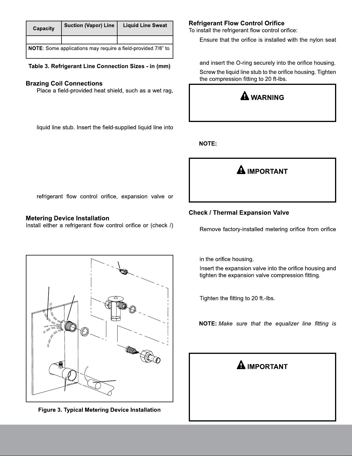
of a refrigerant metering device. Either a refrigerant
a thermal expansion valve (ordered separately) may be
used in condensing unit applications. A check / expansion
valve (ordered separately) is the only metering device
approved for use in heat pump applications.
as shown in Figure 2. Indoor coils will physically match the
furnace supply air opening with the same letter designation
in the model number (see Figure 1).
MCDP*18A MCDP*24A MCDP*24B
Nominal size - tons 1.5 2 2 2.5/3 2.5/3
Suction / vapor o.d. - sweat 7/8 (22.2) 7/8 (22.2) 7/8 (22.2) 7/8 (22.2) 7/8 (22.2)
Liquid o.d. - sweat 3/8 (9.5) 3/8 (9.5) 3/8 (9.5) 3/8 (9.5) 3/8 (9.5)
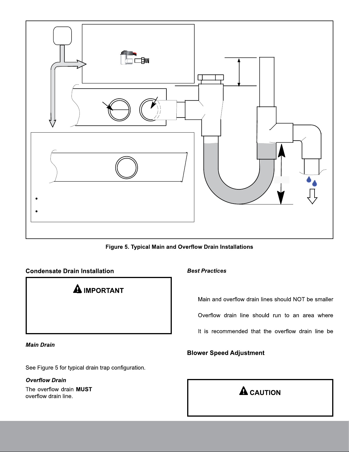
Condensate drain (fpt) (2) 3/4 (19) (2) 3/4 (19) (2) 3/4 (19) (2) 3/4 (19) (2) 3/4 (19)
Net face area sq. ft. (m2) 3.5 (0.33) 3.21 (0.30) 3.21 (0.30) 4.08 (0.38) 4.08 (0.38)
Tube diameter - in. (mm) 3/8 (9.5) 3/8 (9.5) 3/8 (9.5) 3/8 (9.5) 3/8 (9.5)
Number of rows 2 3 3 3 3
Fins per in. (m) 18 (709) 12 (472) 12 (472) 12 (472) 12 (472)
lbs. (kg) 1 package 44 (20) 44 (20) 49 (22) 57 (26) 58 (26)
MCDP*48B
Nominal size - tons 2.5/3 4 4 4/5 5
Suction / vapor o.d. - sweat 7/8 (22.2) 7/8 (22.2) 7/8 (22.2) 7/8 (22.2) 7/8 (22.2)
Liquid o.d. - sweat 3/8 (9.5) 3/8 (9.5) 3/8 (9.5) 3/8 (9.5) 3/8 (9.5)
Condensate drain (fpt) (2) 3/4 (19) (2) 3/4 (19) (2) 3/4 (19) (2) 3/4 (19) (2) 3/4 (19)
Net face area sq. ft. (m2) 4.08 (0.38) 5.25 (0.49) 5.25 (0.49) 6.42 (0.60) 6.42 (0.60)
Tube diameter - in. (mm) 3/8 (9.5) 3/8 (9.5) 3/8 (9.5) 3/8 (9.5) 3/8 (9.5)
Number of rows 3 3 3 3 3
Fins per in. (m) 12 (472) 12 (472) 12 (472) 12 (472) 12 (472)
lbs. (kg) 1 package 60 (27) 71 (32) 72 (33) 84 (38) 85 (39)
Package 1 of 1 contains the following:
1 - MCDP* evaporator coil
1 - Bag assembly containing:
3 - Straight coil locators (24B, 30/36B, 30/36C, 48C,
60D)
3 - Coil locators — 2 angular and 1 straight coil locators
(18A, 24A, 30/36A, 48B, 50/60C)
6 - #8 screws for fastening coil locators
1 - Liquid line stub (3/8” copper swedged)
1 - Warranty card
1 - Installation instructions
damage, immediately contact the last carrier.
MCDP* downflow evaporator coils are designed for use with
MCDP*30/36A MCDP*30/36B
MCDP*30/36C MCDP*48C MCDP*50/60C MCDP*60D
Page 2
mrcool.com