mru RM400 User manual

HC40X
RM400
IR400
RF400
CO400
CD400
Hand detector probe
USER MANUAL
1112EN

USER MANUAL 400DH
2 / 41 MRU GmbH, D-74172 Neckarsulm
Manufacturer:
Legal notices / Intellectual property rights comments
Original user manual
© 2022 by MRU
No part of this manual may be published in any form (print, photocopy, electronic media or any
other publication form) without a written approval by the publisher.
All user trademarks and name mark descriptions, even those which are not marked as such, are
properties of the respective owners.
Edition: 2022-05-24, V1.02.EN

USER MANUAL 400DH
MRU GmbH, D-74172 Neckarsulm 3 / 41
Table of content
1Security and safety directions for the analyser..................................5
1.1. Safety manual .......................................................................................................5
1.2. Safety precautions...............................................................................................5
2Introduction ...........................................................................................6
2.1. Intended Use.........................................................................................................6
2.2. The company MRU..............................................................................................8
3Description.............................................................................................9
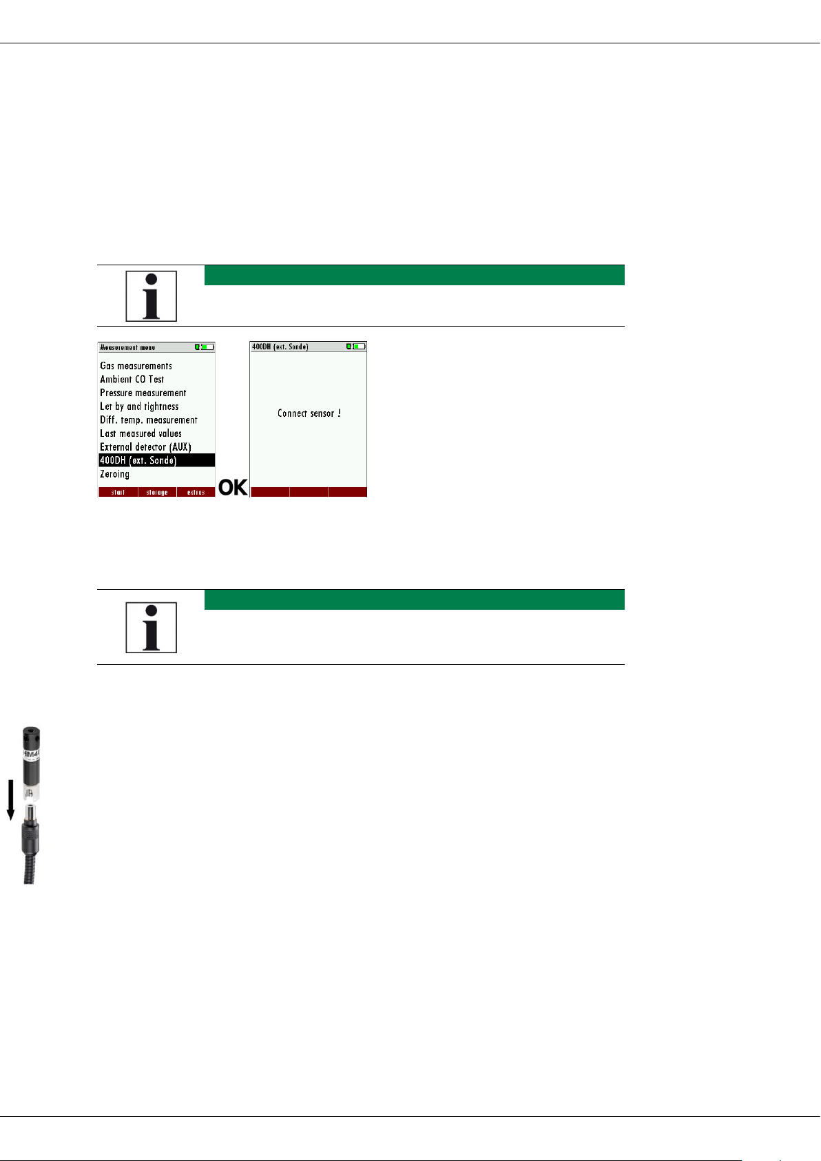
3.1. Connecting Detector Hand Probe 400DH with analyser. ......................9
3.2. Inserting interchangeable Sensor..................................................................9
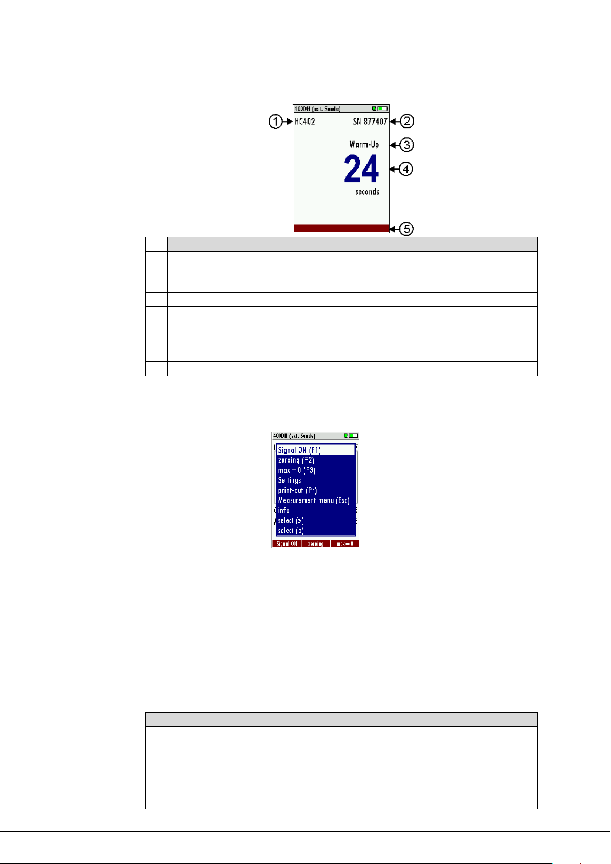
3.3. Terms and window designation.................................................................. 10
3.4. Context menu .................................................................................................... 10
4Measuring............................................................................................ 12
4.1. Measuring with interchangeable sensor HC40X.................................... 12
Starting measurement ............................................................................................ 12
Open context menu................................................................................................. 13
Setting alarm thresholds and units..................................................................... 14
4.2. Measuring with interchangeable sensor RM400 ................................... 16
Starting measurement ............................................................................................ 16
Open context menu................................................................................................. 17
4.3. Measuring with interchangeable sensor RM400 ................................... 19
Starting measurement ............................................................................................ 19
Open context menu................................................................................................. 19
Setting units................................................................................................................ 20
4.4. Measurement with interchangeable sensor IR400................................ 20
Starting measurement ............................................................................................ 21
Open context menu................................................................................................. 22
Setting Alarm threshold, Unit and Emissivity.................................................. 22
4.5. Measurement with interchangeable sensor RF400 .............................. 25
Starting measurement ............................................................................................ 25
Open context menu................................................................................................. 26
Settings Alarm threshold ....................................................................................... 26
4.6. Measurement with interchangeable sensor CO400 ............................. 29
Starting measurement ............................................................................................ 29
Open context menu................................................................................................. 29
Setting alarm threshold and unit ........................................................................ 30
4.7. Measurement with interchangeable sensor CD400 ............................. 31
Starting measurement ............................................................................................ 31

USER MANUAL 400DH
4 / 41 MRU GmbH, D-74172 Neckarsulm
Open context menu..................................................................................................32
Settings alarm threshold.........................................................................................33
5Technical data ..................................................................................... 34
Interchangeable Sensor HC400 (Nr.11138).......................................................34
Interchangeable Sensor HC401 (Nr.11591).......................................................34
Interchangeable Sensor HC402 (Nr.11733).......................................................35
Interchangeable Sensor RM400 (Nr.11191) ......................................................36
Interchangeable Sensor IR400 (Nr.12121).........................................................36
Interchangeable Sensor HM400 (Nr.11922)......................................................36
Interchangeable Sensor RF400 (Nr.11900)........................................................37
Interchangeable sensor CO400 (Nr.12130).......................................................38
Interchangeable sensor CD400 (Nr.12623) .......................................................39
6Declaration of conformity .................................................................. 40

USER MANUAL 400DH
MRU GmbH, D-74172 Neckarsulm 5 / 41
1Security and safety directions for the analyser
1.1. Safety manual
All general information and safety precautions of MRU products are listed in the
supplied separate safety manual.
Therefore, this manual must be read and observed before the first use of the ana-
lyser.
Instrument-specific safety and warning requirements in this manual are pre-
fixed before dangerous actions
1.2. Safety precautions
The used categories of safety precautions are here explained once more
DANGER
Identifies an immediate, impending hazard that, if ignored, will
result in severe bodily injuries or death.
WARNING
Identifies an immediate, impending hazard that, if ignored, may
result in severe bodily injuries, material damage or death.
CAUTION
Identifies a possibly dangerous situation that, if ignored, may re-
sult in minor injuries.
ATTENTION
Identifies a possibly harmful situation that, if ignored, may result
in damages to the device or its surroundings.
NOTE
Identifies user tips and other especially important information.
The explanation of safety notices:
CAUTION
HOT – danger of burns and fire hazards from gas ex-
traction probe.
Physical harm and property damage can be caused.
►Cool down the probe tube.

USER MANUAL 400DH
6 / 41 MRU GmbH, D-74172 Neckarsulm
2Introduction
•Read and observe the safety manual supplied separately.
•This user manual enables you to operate the Hand Detector Probe 400DH
safely.
•Read this user manual carefully.
•Make yourself familiar with the Hand Detector Probe 400DH, before using
it.
•Pay special attention to the security and warning precautions, in
order to prevent injuries and product damages.
•We can’t be held responsible for damages or injuries, by not following the
instructions in this manual.
•Always keep this user manual near you, when working with the Hand De-
tector Probe 400DH, to be able to read instructions as needed.
•Ensure to hand over all documents to when handing the Hand Detector
Probe 400DH over to others.
NOTE
This user manual only describes the Hand Detector Probe
400DH and the available interchangeable
sensors. To operate your analyser, read the corresponding
user manual.
2.1. Intended Use
Due to interchangeable sensors, the Hand Detector Probe 400DH can be
used for a wide range of applications:
•Usable with interchangeable sensor RM400 for leak detection on exhaust
pipes.
•Usable with interchangeable sensor HC400, HC401 and HC402 for leak
detection on gas lines in non-explosive environments.
•Usable with interchangeable sensor RF400 for leak detection on
refrigeration systems.
•Usable with interchangeable sensor HM400 to measure environmental
parameters (air pressure, humidity, air temperature and dew point).
•Usable with interchangeable sensor CO400 for monitoring the CO-con-
centration in the ambient air.
•Usable with interchangeable sensor CD400 for monitoring the CO2-con-
centration in the ambient air.
Note that all interchangeable sensors are developed for indoor use only.
►Do not use the interchangeable sensors outdoor.
The Hand Detector Probe 400DH records the measured values and dis-
plays them on the connected analyser for further processing.
The Hand Detector Probe 400DH cannot be used for personal protection or
continuous monitoring tasks.

USER MANUAL 400DH
MRU GmbH, D-74172 Neckarsulm 7 / 41
The Hand Detector Probe 400DH was manufactured according to rele-
vant standards and regulations. The Hand Detector Probe must be used
according to the instructions for the intended used.
WARNING
Risk from manipulations to the measuring device
Operational safety hazard
Modifications or changes to the measuring device are
not allowed.
The Hand Detector Probe 400DH must not be modified in terms of con-
struction or safety. Modifications of this kind by the user will invalidate
the declaration of conformity

USER MANUAL 400DH
8 / 41 MRU GmbH, D-74172 Neckarsulm
2.2. The company MRU
The 400DH is manufactured by the MRU GmbH in Neckarsulm, Germany
(founded in 1984), a medium sized company that specializes in developing, pro-
ducing and marketing high quality emission monitoring analysers. MRU GmbH
manufactures a wide range of instruments, from standard analysers up to tailor
made industrial analysers
Plant 1: Sales, Service, R&D
Plant 2: Production
MRU GmbH
Fuchshalde 8 + 12
74172 Neckarsulm - Obereisesheim GERMANY
Phone +49 71 32 99 62 0 (Front office)
Phone +49 71 32 99 62 61 (Service)
Fax +49 71 32 99 62 20
Email: info@mru.de
Internet: www.mru.eu

USER MANUAL 400DH
MRU GmbH, D-74172 Neckarsulm 9 / 41
3Description
3.1. Connecting Detector Hand Probe 400DH with analyser.
►Connect the Detector Hand Probe 400DH to the analyser via the AUX
socket.
►The red markings of the AUX socket on the analyser and on the plug the
Detector Hand Probe 400DH must match.
NOTE
If necessary, find out about the position of the AUX socket in the
user manual of the corresponding analyser.
►Select in the Measurement menu the menu item 400DH (ext. Sonde).
►Press OK.
Connect sensor! appears.
NOTE
Note that the Detector Hand Probe 400DH alone does not sup-
port a measurement. Each measuring function is determined by
the inserted interchangeable sensor.
3.2. Inserting interchangeable Sensor
►Insert the desired interchangeable sensor into the sensor connector.
►Make sure that the interchangeable sensor clicks into place audibly.
The analyser automatically identifies the

USER MANUAL 400DH
10 / 41 MRU GmbH, D-74172 Neckarsulm
3.3. Terms and window designation
Function
Explanation
1
Connect probe!
In case of a communication error, check that the probe
is connected to the device via AUX connector and that
an interchangeable sensor is correctly plugged in.
2
SN
The serial number of the mounted sensor is displayed.
3
Warm-up time
Depending on the sensor, a certain time is required to
warm up the sensor to the required operating temper-
ature.
4
Numeric value
Display of the elapsed warm-up time
5
Function bar
Displays the functions available for the sensor used
3.4. Context menu
Depending on the sensor type used, different functions are offered in the context
menu:
Function
Explanation
Signal ON (F1)
If the sensor has a signal threshold, signal ON
appears in the context menu and on the display (Key
F1).
With this function the signal is switched on.
Signal OFF (F1)
If the sensor has a signal threshold, signal ON appears
in the context menu and on the display (F1).

USER MANUAL 400DH
MRU GmbH, D-74172 Neckarsulm 11 / 41
This function turns off the signal.
zeroing(F2)
This function is sensor dependent.
With this function the sensor is zeroed.
Max = 0 (F3)
The value Max is set to zero.
Setting
Depending on the sensor, the units and Signal thresh-
olds are set.
Print-out (Pr)
Printout is generated, a printer is required for this
function.
Measurement menu
(Esc)
Exit measuring program
Info
The information (sensor name, serial number, firmware
version) about the sensor is displayed here.
select (>>) "Arrows
right"
select (<<) "Arrows left"
Varies depending on the interchangeable sensor:
e. g. with HC402:
Switching between CH4, C3H8and H2

USER MANUAL 400DH
12 / 41 MRU GmbH, D-74172 Neckarsulm
4Measuring
4.1. Measuring with interchangeable sensor HC40X
ATTENTION
Damage to the device due to incorrect operation
Destruction of the HC sensor by exceeding the measuring
range
►Observe the meas. range of the HC sensor
►do not exceed the meas. range of the HC sensor.
The interchangeable sensors HC400, HC401 and HC402 are gas sensors
which are used for leak detection on gas lines in non-explosive environ-
ments.
You can use the interchangeable sensor…
•HC400 to detect CH4(methane).
•HC401 to detect CH4(methane) and C3H8 (propane).
•HC402 to detect CH4(methane) C3H8(propane) and H2(hydrogen).
Using the interchangeable sensor HC402 as an example, the following
shows how to start and configure a measurement.
Starting measurement
DANGER
Risk due to improper use
Fatal accidents may occur if the measurement rules are
disregarded.
►Only use the measuring device to locate gas leaks in the
installation area.
►Even if the sensor does not locate a leak, this is not suffi-
cient proof of the tightness of a pipe system. Observe
the relevant valid rules.
DANGER
Danger when used improperly
Deadly accidents can be the result if the rules are not
obeyed.
The analyser may only be used for its intended
purpose.
DANGER
Explosion danger in EX zones
There is a possibility of explosion in an EX-zone.
The analyser may only be used in explosion free
zones.

USER MANUAL 400DH
MRU GmbH, D-74172 Neckarsulm 13 / 41
►Connect the Detector Hand Probe 400DH with the analyser.
See also chapter 3.1 Connecting Detector Hand Probe 400DH with an-
alyser., page 9.
►Insert the desired interchangeable sensor into the sensor connector.
See also chapter 3.2 Inserting interchangeable Sensor, page 9.
After the warm-up the analyser automatically switches to the meas-
uring mode.
The measurement starts.
►If necessary, press the left/right arrow keys to switch between the availa-
ble measured values.
►If necessary, press F2 to take a new zero point.
►Guide slowly the interchangeable sensor along the areas to be tested.
If there is a leakage, the measured value changes.
The measurement process is displayed graphically.
Optical and acoustic alarm signals indicate gas leakage.
The flashing frequency of the red LED in the sensor foot increases
with the increase of the measured gas concentration.
Open context menu
In the context menu you can configure the measurement.
►Press the context menu key.
The context menu
►Select the desired option.

USER MANUAL 400DH
14 / 41 MRU GmbH, D-74172 Neckarsulm
Function
Explanation
Signal ON (F1)
With this function the signal is switched on.
Signal ON (F1)
With this function the signal is switched off.
max=0 (F3)
The value max is set to zero
zeroing (F2)
With this function the sensor is zeroed.
print-out (Pr)
Printout is generated, a printer is required for this
function.
Measurement menu
(Esc)
Exit measuring program
settings
Settings units Alarm thresholds
See also Chapter Setting alarm thresholds
and units, page 14.
Info
The information (sensor name, page number, firmware
version) about the sensor is displayed here.
select (>>) (<<)
„Arrows right/left“
HC401: Switching between CH
4
, C
3
H
8
HC402: Switching between CH
4
, C
3
H
8
and H
2
Setting alarm thresholds and units.
You can set a defined alarm threshold for each measured value.
As soon as the defined alarm threshold is exceeded, an alarm is issued.
You can change the unit for each measured value.
►Go to the context menu.
►Select settings.
►Press OK.
A menu appears.
►Set the desired alarm threshold and unit for each measured value sepa-
rately.
►Press ESC.
The measurement starts/continues.
As soon as the set alarm threshold is exceeded, the measured value
turns red and an acoustic alarm signal will sound.

USER MANUAL 400DH
MRU GmbH, D-74172 Neckarsulm 15 / 41
Gas
Adjustable Signal thresholds
CH
4
[ppm]
10 … 500 ppm
CH
4
[%]
0,001 … 0,050 %
CH
4
[% LEL]
0,02 … 1,14 % LEL
C3H8[ppm]
10 … 500 ppm
C
3
H
8
[%]
0,001 … 0,050 %
C
3
H
8
[% LEL]
0,06 … 2,94 % LEL
H
2
[ppm]
10 … 500 ppm
H
2
[%]
0,001 … 0,050 %
H
2
[% LEL]
0,03 … 1,25 % LEL

USER MANUAL 400DH
16 / 41 MRU GmbH, D-74172 Neckarsulm
4.2. Measuring with interchangeable sensor RM400
The interchangeable sensor RM400 is used for leak detection on flue gas
pipes.
NOTE
The RM400 operates on a conductive sensor surface, so do not
clean with alcohol or distilled water.
If necessary, clean the sensor surface with saline water and al-
low it to dry
Starting measurement
DANGER
Risk due to improper use
Fatal accidents may occur if the measurement rules are
disregarded.
►Only use the measuring device to locate gas leaks in the
installation area.
Before measuring, remove the protective cap from the interchangeable sensor.
For measurement, the sensor surface must be dry and at room temperature.
►Connect the Detector Hand Probe 400DH with the analyser.
See also chapter 3.1 Connecting Detector Hand Probe 400DH with an-
alyser., page 9.
►Insert the desired interchangeable sensor into the sensor connector.
See also chapter 3.2 Inserting interchangeable Sensor, page 9.
The measurement starts.
►If necessary, press the left/right arrow keys to switch between low sens
and high sens.
NOTE
The interchangeable sensor RM400 can sometimes be too sen-
sitive (e. g. in summer with high humidity).
You can reduce the sensitivity with "low sens".
►If necessary, press F2 to take a new zero point.
►Guide slowly the interchangeable sensor along the areas to be tested.
If there is a leakage, the measured value changes.

USER MANUAL 400DH
MRU GmbH, D-74172 Neckarsulm 17 / 41
The measurement process is displayed graphically.
Optical and acoustic alarm signals indicate gas leakage.
The flashing frequency of the red LED in the sensor foot increases
with the increase of the measured gas concentration.
Open context menu
In the context menu you can configure the measurement.
►Press the context menu key.
The context menu
►Select the desired option.
Function
Explanation
Signal ON (F1)
With this function the signal is switched on.
Signal OFF (F1)
With this function the signal is switched off.
max=0 (F3)
The value max is set to zero.
zeroing
With this function the sensor is zeroed.
print-out (Pr)
Printout is generated, a printer is required for this
function.
Measurement menu
(ESC)
Exit measuring program
Info
The information (sensor name, serial number, firmware
version) about the sensor is displayed here.
select (>>) (<<)
„Arrows right/left“
Switching between high sens and low sens

USER MANUAL 400DH
18 / 41 MRU GmbH, D-74172 Neckarsulm
NOTE
The RM400 operates on a conductive sensor surface, so do not
clean with alcohol or distilled water.
If necessary, clean the sensor surface with saline water and al-
low it to dry
DANGER
Danger due to improper use
Non-compliance with the measurement rules can result in fatal
accidents.
The meter may only be used for advertising purposes to locate
gas leaks in the installation area.

USER MANUAL 400DH
MRU GmbH, D-74172 Neckarsulm 19 / 41
4.3. Measuring with interchangeable sensor RM400
The interchangeable sensor HM400 is used to measure ambient
parameters.
You can use the interchangeable sensor to…
•to measure the air humidity
•to measure the dew point
•to measure the air pressure
•to measure the air temperature
Starting measurement
►Connect the Detector Hand Probe 400DH with the analyser.
See also chapter 3.1 Connecting Detector Hand Probe 400DH with an-
alyser., page 9.
►Insert the desired interchangeable sensor into the sensor connector.
See also chapter 3.2 Inserting interchangeable Sensor, page 9.
The measurement starts.
With the interchangeable sensor HM400, it is possible to display all meas-
ured values on the display. However, you also have the option of displaying
a single measured value with a measurement curve in the display.
►If necessary, press the left/right arrow keys to switch between the overall
display and the single measured values.
Open context menu
In the context menu you can configure the measurement.
►Press the context menu key.
The context menu
►Select the desired option.

USER MANUAL 400DH
20 / 41 MRU GmbH, D-74172 Neckarsulm
Function
Explanation
Signal ON (F1)
With this function the signal is switched on.
Signal OFF (F1)
With this function the signal is switched off.
max=0 (F3)
The value max is set to zero.
print-out (Pr)
Printout is generated, a printer is required for this
function.
Measurement menu
(ESC)
Exit measuring program
settings
Setting units
See also Chapter Setting units, Page 20.
Info
The information (sensor name, serial number, firmware
version) about the sensor is displayed here.
select (>>) (<<)
„Arrows right/left“
Switch between overall view and view of the single
measurands as individual graphs.
Setting units
►Go to the context menu.
►Select settings.
►Press OK.
A menu appears.
►Select the desired measurand.
►Set the desired unit.
►Press ESC.
The unit is assigned to the corresponding measurand.
Measurand
Adjustable units
Humidity
% (relative), g/m
3
(absolute)
Dew point
° C, ° F
Air pressure abs.
hPa, inHG, mmHG, mmH
2
O
Temperature
° C, ° F
4.4. Measurement with interchangeable sensor IR400
The IR400 interchangeable sensor is used for non-contact temperature
measurement.
This manual suits for next models
5
Table of contents
Other mru Analytical Instrument manuals