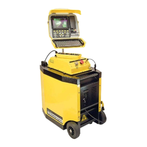
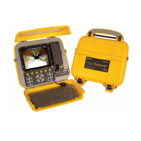
SPX Radiodetection Pearpoint P571 Flexicoiler User manual

P571 flexicoiler
Pearpoint’s comprehensive Explosion-proof
pushrod inspection system
Operation Manual
90/HK571UM-4


P571 flexicoiler Operation Manual i
Copyright Notice
The information within this handbook is authorized for distribution to customers, authorized service center
personnel, and distributors of Pearpoint.
Copyright 2016 Radiodetection Ltd –SPX Corporation. All rights reserved. Radiodetection is a subsidiary
of SPX Corporation. SPX, Radiodetection and Pearpoint are trademarks of Radiodetection Ltd. and SPX
Corporation. Due to a policy of continued development, we reserve the right to alter or amend any
published specification without notice. This document may not be copied, reproduced, transmitted,
modified or used, in whole or in part, without the prior written consent of Radiodetection Ltd.
Warranty
The manufacturer's warranty will be invalidated if the equipment is operated by untrained personnel or if
any attempt is made to service the equipment by untrained personnel. No camera body is to be opened
under any circumstance as damage to the CCD might result.
Trademarks
Flexiprobe is a trademark of Radiodetection Ltd, all rights reserved.
SPX, Radiodetection and Pearpoint are trademarks of SPX Corporation and Radiodetection Ltd.
Other trademarks or registered trademarks mentioned in this document belong to their respective owners.
Compliance
EU Compliance
This equipment complies with the following EU Directives.
Low Voltage Directive: 2014/35/EU
Machinery Directive: 2006/42/EC
EMC Directive: 2014/30/EU
R&TTE Directive: 2014/55/EC
This equipment complies with Part 15 of the FCC Rules. Operation is subject to the following two
conditions:
The equipment may not cause harmful interference. The equipment must accept any interference
received, including interference that may cause undesired operation.
NOTE: This equipment has been tested and found to comply with the limits for a Class A digital device
pursuant to Part 15 of the FCC Rules. These limits are designed to provide reasonable protection against
harmful interference when the equipment is operated in a commercial environment. This equipment
generates, uses, and can radiate radio frequency energy and, if not installed and used in accordance with
the manufacturer’s instruction manual, may cause harmful interference with radio communications.
Operation of this equipment in a residential area is likely to cause harmful interference, in which case you
will be required to correct the interference at your own expense.
Modifications: Any modifications made to this equipment that are not approved by Radiodetection Ltd.
may void the authority granted to the user by the FCC to operate this equipment.
Industry Canada compliance statements
ICES-003 Class A Notice: This Class A digital apparatus complies with Canadian ICES-003. Avis NMB-
003, Classe A: Cet appareil numérique de la classe A est conforme à la norme NMB-003 du Canada.
Conditions of Sale
Pearpoint systems are sold subject to the Radiodetection Ltd. General Conditions of Sale.
Disposal
Do not dispose of this product in municipal waste facilities. Please check local regulations for disposal of
electronic products. Radiodetection complies with the requirements of 2012/19/EU Waste Electrical and
Electronic Equipment.

ii
Disclaimer
Any third-party products (including hardware, software and services) mentioned in this manual are for
instructional purposes only and is not an endorsement by Radiodetection Ltd and SPX Corporation.
Radiodetection Ltd does not accept any liability for loss of data or damage to equipment when using any
third-party products.
Every effort has been made to supply information within this handbook which is correct. However,
Radiodetection Ltd. assumes no responsibility for its use, nor any infringements of patents or other rights
of third parties which would result. No license is granted by the manufacturer under any patent or patent
rights. The manufacturer reserves the right to modify and update the equipment at any time without prior
notice.
Training
Pearpoint provides training services for most Pearpoint products. Our instructors will train equipment
operators or other personnel at your preferred location or at Pearpoint headquarters.
For more information go to www.pearpoint.com
SAFETY PRECAUTIONS
WARNING:These guidelines are not intended to REPLACE A RISK ASSESSMENT.
Ensure that standard safety precautions for working in hostile environments are followed.
The P571 flexicoiler Inspection Systems are designed to reduce hazards from electric shock provided
that proper operating procedures are followed. It is also good practice to use a Ground Fault
Interrupter (GFI) to increase the safety factor.
Always use heavy duty industrial gloves when handling rod or cable which is being withdrawn from a
sewer.
Always ensure that cabling is properly connected.
A portable generator can be a hazard if not properly operated. Always follow the manufacturer's
instructions.
Always transport a generator with the minimum amount of fuel in the tank.
Never connect or disconnect any part of the equipment when it is switched on.
Always switch the system on and off using the power controls.
Never lower tractors or other heavy equipment into manholes while personnel are working in the
manhole.
To avoid risk of burns do not touch lightheads when they are switched on or immediately after switch
off. Leave ample time for them to cool before handling.
Clean and sterilize equipment at regular intervals.
Explosion Proof (EX) camera systems have been certified by approved certification authorities. Users
of such systems must ensure that they are operated and serviced according to the instructions
contained in the User and Maintenance manuals. It is the responsibility of the user to decide if the
systems are suitable for use in a particular environment.
Guidance Notes for using CCTV equipment in sewers
All equipment should be properly maintained and should be checked before use to ensure it is
functioning safely.
Select and cone off area to be surveyed. Use appropriate signs for directing traffic flow.
Remove manhole covers from survey area. Where reasonably practicable at least one manhole
above and one below the length of pipe to be surveyed should be removed.
If personnel are to enter the manhole, insert an approved gas monitor, on a line, to test the
atmosphere at the pipe level where manhole covers have been raised.
If all the above tests are negative, leave a gas monitor in the sampling mode at the beginning and end
manholes of the area to be surveyed.

P571 flexicoiler Operation Manual iii
Place the survey vehicle and other associated equipment no less than 5 feet (1.5 meters), horizontally,
from the end of the manhole.
Proceed with surveying as per CCTV manufacturers' instructions.
In the event of an alarm on the gas monitor, DO NOT ENTER MANHOLE.
Persistent alarms may require jetting operations or opening more manholes above and below the area
to be surveyed to increase ventilation.
When the survey has been completed, the above sequence of operations should be reversed and, in
particular, the removal of the gas monitors should be left until the end.
Please ensure all personnel observe the NO SMOKING rule throughout the time the manhole covers
are removed.
SPECIAL NOTICES
Within this handbook, pay particular attention to Warnings, Cautions, and Notes, examples of which are
shown below.
WARNING: Indicates the possibilityof personal injury if instructions are not followed carefully.
CAUTION: Indicates a possibility of equipment damage if the instructions are not followed carefully.
NOTE: Gives added information that will make operation of the equipment easier.
This manual covers several variations of P571 flexicoiler.
Please ensure time is taken to identify your system and all components.
Take notice of any specific warnings may apply.
WARNING. For EX systems refer toengraving for compatible modules

iv
Contents
Copyright Notice......................................................................................................................................... i
Warranty..................................................................................................................................................... i
Trademarks................................................................................................................................................ i
Compliance ................................................................................................................................................ i
Conditions of Sale...................................................................................................................................... i
Disposal...................................................................................................................................................... i
Disclaimer...................................................................................................................................................ii
Training ......................................................................................................................................................ii
SAFETY PRECAUTIONS ..........................................................................................................................ii
Guidance Notes for using CCTV equipment in sewers .............................................................................ii
SPECIAL NOTICES..................................................................................................................................iii
Contents....................................................................................................................................................iv
Section 1 - Introduction ...........................................................................................................................1
1. Purpose of this manual.....................................................................................................................1
2. P571 Ex flexicoiler system components...........................................................................................2
Section 2 - Preparation and connection..................................................................................................8
1. Introduction.......................................................................................................................................8
2. Tools and Materials...........................................................................................................................9
3. Equipment preparation ...................................................................................................................10
4. Connecting rod to camera ..............................................................................................................18
5. Testing the system..........................................................................................................................21
6. Disconnecting the rod system.........................................................................................................23
Section 3 - Operation ............................................................................................................................25
1. Introduction.....................................................................................................................................25
2. Monitor controls ..............................................................................................................................25
3. System settings...............................................................................................................................26
4. P571 information.............................................................................................................................30
Section 4 - Maintenance .......................................................................................................................32
1. P571 flexicoiler maintenance..........................................................................................................32
2. P415 camera maintenance.............................................................................................................32
3. Lighthead maintenance ..................................................................................................................34
4. Returns procedure..........................................................................................................................37
Section 5 - Fault finding ........................................................................................................................38
Section 6 - Appendix 1..........................................................................................................................39
1. Specification....................................................................................................................................39
2. Outline of flameproof regulations....................................................................................................41
3. Conversion Tables..........................................................................................................................42
4. Glossary of commonly used terms .................................................................................................59
Tables
Table 1.1 P571 flexicoiler System Components........................................................................................... 2
Table 2.1 Tools and Materials ..................................................................................................................... 9
Table 2.2 Screw Details............................................................................................................................... 9
Table 5.1 Faultfinding Guide....................................................................................................................... 38
Table A4.1 Temperature Conversion ........................................................................................................ 42
Table A4.2 Torque Conversion.................................................................................................................. 55
Table A4.3 Length Conversion.................................................................................................................. 56
Table A4.4 Pressure Conversion............................................................................................................... 57
Table A4.5 Depth and Pressure Chart ...................................................................................................... 58

P571 flexicoiler Operation Manual 1
Section 1 - Introduction
1. Purpose of this manual
This user manual will provide the reader with sufficient information to operate the P571 flexicoiler system
safely and to carry out any routine maintenance tasks which may be necessary.
NOTE: This manual is to be read and clearly understood before operating the equipment.
1.1.1 Layout of the manual
The manual is organized into Sections as follows:
Section 1
This gives an outline description of the basic system components and a description of the various options
that can be used. A schematic diagram of the system is shown as well as a detailed description of each of
the components.
Section 2
This Section discusses the mechanical operations required to prepare and connect each of the
components of system.
Section 3
This Section describes the operation of the system.
Section 4
This Section deals with maintenance of the system.
Section 5
This is a basic trouble-shooting guide that helps in the diagnosis of the most common problems and, in
most cases, suggests the appropriate corrective action.
Appendices
At the back of the manual the appendices include:
A brief specification of the system.
Outline of flame proof regulations.
Metric/Imperial conversion tables for units used in the manual.
Glossary of commonly used terms.

2
2. P571 Ex flexicoiler system components
Figure 1.2 P571 flexicoiler System Components
Item No.
Module
Type
1
P571
Reel/Command
module
2
P415
Cameras
3
P455
4
P417
Lightheads
5
P418
Table 1.1 P571 flexicoiler System Components

P571 flexicoiler Operation Manual 3
1.2.1 P571 Coiler
Figure 1.3 P571 Coiler
The P571 flexicoiler is a fully integrated unit featuring a versatile coiler running up to 150 meters (500
feet) of rod; built-in integral electronic rod counter; video/in and video/out VCR connectors for recording
and playback of surveys; built-in sonde; on-screen text overlay for annotation of inspection findings; and a
QWERTY keyboard built directly into the monitor case allowing up to 512 characters per page (nine page
overlay facility).
Controls such as contrast and brightness are also located on the monitor casing. The P571 is powered by
100 - 240V AC at 50 –60 Hz.
Constructed of rugged, rust-proof cast/welded aluminum the P571 is a stand-alone system.
For use with the Explosion Proof P415 Rotational or the P455 Twin View Color flexiprobe™ Cameras, the
P571 accepts lightheads of up to 40 Watts

4
1.2.2 Ex rod
The rod is supplied installed onto the coiler and complete with explosion proof sonde. The rod is very
flexible and can be pushed round 90° bends in 50mm (2”) diameter pipes. The rod is available in various
standard lengths as follows:
P571 Large Coiler rod
10/HS4162001 75m (225 ft)
10/HS4162101 100m (300 ft)
10/HS4162201 120m (360 ft)
10/HS4162301 150m (450 ft)
1.2.3 Cameras
1.2.3.1 P415 rotational color flexiprobe™ camera
Figure 1.4 P415 rotational color flexiprobe™ camera
Ex 10/HC4154001-1 (PAL) / HC4154101-1 (NTSC)
The P415 Camera is a small color camera, capable of giving high-quality pictures with a minimum of
lighting. Versions for both of the popular TV standards (525-line NTSC or 625-line PAL) are available.
The P415 Camera is auto uprighting. The image is automatically orientated to the correct position
wherever the camera may rest within the pipe. The camera is also equipped with manually operated full
360 degree image rotation, remote electronic iris, and remote focus.
The camera is fully enclosed in a watertight (to 11 bar / 160 PSI) stainless steel case, with all connections
made via waterproofed connectors. Ingress protection is to IP68. At the rear, a slipring assembly picks
up power from a pogo-equipped connector. A slipring on the front of the camera provides power for the
lighthead used.
A patented hose assembly connects to the rear of the camera. This allows the camera to move
independently from the rod and decouples it from any twisting motion that the rod might try to impose.
The camera can thus negotiate right-angled bends in pipes as small as 100mm (4”) in diameter. The rod
also provides power to (and carries video from) the camera.
1.2.3.2 P455 rotational twin view color flexiprobe camera
Figure 1.5 P455 twin view color flexiprobe camera
Ex 10/HC4551501-1 (PAL) / 10/HC4551601-1 (NTSC)

P571 flexicoiler Operation Manual 5
The P455 Twin View Camera is a small color camera, capable of giving forward view and remote side
view maintaining high-quality pictures with a minimum of lighting. Versions for both of the popular TV
standards (625-line PAL or 525-line NTSC) are available.
The P455 Camera is auto uprighting. The image is automatically orientated to the correct position
wherever the camera may rest within the pipe. The camera is also equipped with manually operated full
360 degree image rotation, remote electronic iris, and remote focus.
The camera is fully enclosed in a watertight (to 11 bar/160 PSI) stainless steel case, with all connections
made via waterproofed connectors. Ingress protection is to IP68. At the rear, a pogo-equipped
connector assembly picks up power from a slipring.
A patented hose assembly connects to the rear of the camera. This allows the camera to move
independently from the rod and decouples it from any twisting motion that the rod might try to impose.
The camera can thus negotiate right-angled bends in pipes as small as 100mm (4”) in diameter. The rod
also provides power to (and carries video from) the camera.
1.2.4 Skids / Brushes
Figure 1.6 P455 Skids
10/HC4552001-1 BRUSH SKID SET 4” (100MM):
10/HC4552101-1 BRUSH SKID SET 6” (150MM):
A variety of skids and brushes that can be used with the camera are available as optional extras. The
skids and brushes allow the camera to be used in larger pipes by maintaining the camera in a central
position in the pipe.
Fitting instructions are included in Section 2.
Figure 1.7 P455 Brushes
04/HC45520131 BRUSH 4” (100MM) - Note 16 brushes = 1 set
04/HC45521111 BRUSH 6” (150MM) - Note 16 brushes = 1 set
Additional sets of 4” (100mm) or 6” (150mm) brushes are available, sixteen brushes per set. The brushes
help to center the camera when used in 4” (100mm) and 6” (150mm) pipes. Users can cut down either
the 4” or 6” brushes for custom sizes. Changing instructions are included in Section 4.
Note: These brushes are sold individually.

6
1.2.5 P417 10W Lighthead
Figure 1.9 P417 10W Lighthead
Ex (P417) 10/HI4170001
The P417 is a medium-powered lighthead, using two 5W quartz-iodine lamps to give a rating of 10W.
Ingress protection is to IP68.The lighthead takes its power from the slip rings on the front of the camera.
The lighthead can be fitted with exchangeable brushes that, together with a rear brush holder, allow the
camera and lighthead to be used in either 4” (100mm) or 6” (150mm) pipe. Each brush holder supports
six brushes, equally spaced around the circumference.
1.2.6 P417 10W Lighthead –Brush skid set
Figure 1.10 P417 Lighthead Brush Skid Set
04/HI2220801 BRUSH SET 6” (150MM)
04/HI2220901 BRUSH SET 4” (100MM)
The P417 Lighthead is supplied with a set of six 4” (100mm) brushes. An additional set of six 6” (150mm)
brushes is available. The brushes help to center the camera and lighthead when used in 4” (100mm) and
6” (150mm) pipes. The procedure for changing the brushes is detailed in Section 4.

P571 flexicoiler Operation Manual 7
1.2.7 P418 40W Lighthead
Figure 1.11 P418 40W Lighthead
Ex (P418) 10/HI4180001
The P418 is a larger lighthead containing two 20W quartz-iodine lamps. The lighthead takes its power
from the slip rings at the front of the camera which fits within the lighthead.
Ingress protection is to IP68, see Appendix 2. Two skid mounts at the bottom and a single skid on the top
are fitted as standard, allowing the basic unit to be used in pipes from 6” (150mm) to 18” (450mm)
diameter. The lighting performance is greatly dependent upon the pipe material at the larger diameters.
1.2.8 P418 Lighthead –skid set
Figure 1.12 P418 Lighthead - Skid Set
Additional skids are available for the basic P418 Lighthead which will allow you to survey pipes up to 18”
(450mm). These skids are color coded as follows:
04/HI2230601 6” (150mm) Gloss Brown
04/HI2230801 8” (200mm) Black
04/HI2231001 10” (250mm)Blue
04/HI2231201 12” (300mm)Brown
04/HI2231501 15” (375mm)Green
04/HI2231801 18” (450mm)Grey
Note: Skids are sold individually. 2 skids = set

8
Section 2 - Preparation and connection
1. Introduction
This Section details the correct procedure to safely prepare and connect the P571 flexicoiler System.
WARNING: Risk of explosion.
Do not use any Explosion Proof equipment if there is damage to the body or any other part. The explosion
proof certification maybe violated rendering the equipment unsafe to use in a hazardous environment. Contact
your Pearpoint representative immediately.
Cautions:
1. Any repair work to Explosion Proof equipment must be carried out by an approved person, only.
2. Before proceeding to connect your system, read the section below on flame paths.
2.1.1 Flame paths
At all stages of operation, particular attention must be given to flame paths because the condition of all
flame paths affect the safe operation of the equipment. Within this manual there are illustrations which
show the locations of the flame paths for all of the Explosion Proof items of the system. You will note
that they are, without exception, the external mating surfaces of revolving joints.
The critical features are:
The surface finish of the mating faces
The gap between the mating faces
The length of the mating faces
You must not, as part of any operational or maintenance procedure, do anything which will:
Roughen the surface finish on the face
Change the width of the gap between the mating faces
Reduce the length of the mating faces
If you know, or suspect, that any of the critical features have been adversely affected during surveying
operations, you must take immediate steps to correct the problem. However, this type of problem would
normally occur only as a result of severe impact damage or if there had been an explosion within the
device.
If equipment returned for maintenance has suffered an internal explosion, it is imperative that all the flame
paths are checked before returning it to use. Damage to the surface finish can only occur as a result of
careless assembly since once the equipment is assembled all of the mating surfaces are protected.
Damaged flame paths cannot be reworked. A new, replacement part must be fitted.
It is important to inspect flame paths at regular intervals. We suggest six months as the maximum
interval to ensure that the surface finish and dimensions are correct. If the equipment has been stowed
with its protective caps in place and has not suffered impact damage, it is unlikely that there will be any
damage to the flame paths.
To summarize: Equipment which is carefully assembled and disassembled during survey work should
not suffer damage to flame paths. During surveying, flame paths may suffer damage as the result of
internal explosion or if visible impact damage occurs.

P571 flexicoiler Operation Manual 9
2. Tools and Materials
2.2.1 Tools and equipment
Table 2.1 lists the cleaning materials, lubricants, and general purpose tools required to prepare the
equipment. If additional special tools are required, these are called up in the relevant paragraph.
Table 2.1 Tools and Materials
Description
Part No
Cleaning kit containing:
HT4003501
Cleaning brush
04/B20567575
Ambersil Ambertron spray
12/B3502
Ambersil 40 plus
12/B3506
Silicone grease
12/B27101687
Anti static cleaning foam
12/B24
Wrench key long series
04/B200009AFL
Wrench key set (Ball end)
04/B2010999
In addition you will need:
Posidriv screwdriver
Loctite
See Table 2.2
"Rubert" roughness gauge
Clean lint free cloths
2.2.2 Screw fasteners
Most of the screws that need to be adjusted or are used to secure equipment are of the socket head cap
screw type. Throughout this Section screws are referred to by their size not by the size of the wrench key
that fits them. The required size of key can be obtained from Table 2.2 below.
Screws must be tightened to the minimum torque indicated in this table. A conversion table from
Newton/meters to pounds/feet is given in section 6.3
If Loctite is required for locking screws it will be specifically mentioned in the text.
Table 2.2 Screw Details
ISO fastener Quality 8.8
Loctite Type
Screw Size
Wrench Key
Torque
M1.6
0.89mm AF
0.19 Nm
222
M2.5
1.27mm AF
0.77 Nm
222
M3
2.50mm AF
1.4 Nm
222
M4
3.00mm AF
3.2 Nm
243
M5
4.00mm AF
6.4 Nm
243
M6
5.00mm AF
10.9 Nm
243
M8
6.00mm AF
26.1 Nm
638

10
3. Equipment preparation
This section details the preparation to the P571 flexicoiler which is necessary prior to commencing the
survey. Most of the checks are to ensure that the equipment is safe to use. Other checks, if carried out
correctly, will ensure that the equipment operates correctly during the survey.
2.3.1 P571 preparation
WARNING: Risk of explosion.
Do not use the P571 flexicoiler if there is damage to the body or any other part. The certification may be
violated rendering the equipment unsafe to use in a hazardous environment. Contact your Pearpoint
representative immediately.
WARNING: Risk of injury.
Heavyduty gloves and safety goggles should be worn when handling rod. Any abrasions or damage on the
rod outer covering can cause injuryto unprotected hands.
Figure 2.1 P571 flexicoiler - Preparation
1. Check the power cable (Item 1) for damage and security. If the cable or plug is damaged in any
way it must be replaced.
2. Inspect the frame (Item 2) to ensure that there is no damage or distortion. Inspect all welds for signs
of cracking. If any damage is apparent, contact your Pearpoint representative for advice.
3. Check the condition of the hub connector. Ensure it is secure and not damaged or dirty. If the
connector has been damaged, contact your Pearpoint representative for advice.
4. Remove all rod from the coiler and inspect for damage. If the rod is damaged, water may leak
through the outer covering and damage the equipment. Contact your Pearpoint representative
for advice.
NOTE: It is also necessary to calibrate the rod before use. This will ensure that the rod counter will give
accurate measurements. See Section 3 for details.

P571 flexicoiler Operation Manual 11
5. Check the security of the monitor locking hand wheel (Item 5). Turn the hand wheel anticlockwise to
loosen and push the monitor to the upright position. Turn the hand wheel clockwise until hand tight
to secure the monitor. The monitor should remain in the upright position.
CAUTION: Equipment Damage.
If the monitor fails to remain upright, there could be a fault in the hand wheel mechanism. This must be
repaired otherwise damage to the monitor may result. Contact your Pearpoint representative for advice.
6. Inspect the monitor for damage. Check the casing for cracks and ensure the rear cover is secure.
Check the screen for damage. Pull out the sun visor and inspect for damage and security. If any
damage to the monitor is apparent, contact your Pearpoint representative for advice.
7. Check the action of the brake (Item 7) by releasing it sufficiently to remove rod from the coiler. Lock
the brake and ensure that the coiler will not move.
CAUTION: Do not release the brake completely. The tension of the rod is such that it will feed off the
coiler by itself if not checked by the brake.
2.3.2 P415 camera –preparation
Figure 2.2 P415 Camera –Preparation
WARNING: Risk of explosion.
Do not use the P415 camera if there is damage to the body or anyother part. The certification maybe violated
rendering the camera unsafeto use in a hazardous environment. If damaged contact your Pearpoint
representative immediately.
1. Remove protective caps - one from each end - and stow safely (not shown).
2. Check the ‘O’ rings (2) (four in total) and replace if damaged. Apply a thin film of silicon grease.
3. Examine the sliprings (3) at front and rear for cleanliness and wear. Do not use if scratched or
pitted. Clean with Ambersil Ambertron and apply a thin film of silicon grease.
4. Check the three M3x5 socket head grub screws (4) in hose connector for tightness.
5. Check that the certification engraving on the camera body (5) is shown in Figure 2.2.
6. Check that front glass (6) is not cracked. Clean using soft cloth and Ambersil Ambertron spray.
7. Check appearance of the flame paths (7). Do not use if scratched or distorted. Read the note at the
beginning of Section 2 about flame paths if you are unsure about inspecting them.

12
8. Check body (8). Do not use camera if body is dented or distorted. (See warning).
9. Check hose (9) is not cracked or split.
10. Check three M2x3 socket head cap screws (10) are in place on the sonde connector.
2.3.3 P41525 camera –hose preparation
The camera hose must be properly prepared before use. This involves removing the hose from the
camera, if fitted.
Figure 2.3 P415 Camera –Hose Preparation
2.3.3.1 Removing the camera hose
1. Loosen, but do not remove, the M3x5 socket head grub screws in the camera hose locking ring (3) at
the end of the camera.(The screws are identified as Item 4 in Figure 2.1.)
2. Unscrew the camera hose locking ring and withdraw it over the spring.
3. Grasp the hose assembly around the spring and pull out the pogo block (2) from the rear of the
camera. Use a straight pull and do not twist the block.
4. When free, clean the pogos and the sliprings at the other end of the assembly with Ambersil
Ambertron spray. Apply a small amount of silicone grease to the sliprings. Stow the camera hose
assembly.
CAUTION: The rear of the camera is not watertight when the hose is removed. Keep the camera in a
clean and dry place until it is refitted to the hose.
2.3.3.2 Attaching the Hose
1. Carefully check the flame paths (1) for impact distortion and scratches. Do not use if they are
scratched or distorted. Read the note at the beginning of Section 2 about flame paths if you are
unsure about inspecting them.
2. Check the ‘O’ rings (4) and replace if damaged. Apply a thin film of silicone grease. See Section
4 for a list of replacement parts.
3. Check the cleanliness and smooth movement of the pogos (5). Do not use if damaged.
4. Line up the locating pin on the pogo block (2) with the corresponding hole in the rear of the
camera. Push the pogo block gently into the camera rear.
5. Screw the hose locking ring (3) onto the rear of the camera and tighten using the special tool.
6. Tighten the three M3x5 socket head grub screws.

P571 flexicoiler Operation Manual 13
2.3.4 P455 camera preparation
Figure 2.4 P455 Camera Preparation
WARNING: Risk of explosion.
Do not use the P455 camera if there is damage to the body or anyother part. The explosion proof certification
may be violated rendering the camera unsafe to use in a hazardous environment. If damaged contact your
Pearpoint representative immediately.
1. Remove protective cap (item 5) from the rear of the camera and stow safely.
2. Check the ‘O’ rings (item 2) and replace if damaged. Apply a thin film of silicone grease.
3. Examine the slipring (item 3) at the rear for cleanliness and wear. Do not use if scratched or pitted.
Clean with Ambersil Ambertron and apply a thin film of silicone grease.
4. Check the three M4x4 socket head grub screws (item 4) in hose connector for tightness.
5. Check that the certification label viewable through the side glass (item 8) is as shown in Figure 2.4.
6. Check the front window (item 6) and the side window (item 8) are not cracked. Clean using soft cloth
and Ambersil Ambertron spray.
7. Check appearance of the flame path (item 7). Do not use if scratched or distorted. Read the note at
the beginning of Section 2 about flame paths if you are unsure about inspecting them.
8. Check the camera body (item 8). Do not use camera if the body is dented or distorted. (See
warning.)
9. Check hose (item 9) is not cracked or split.
10. Check three M2x4 socket head cap screws (item 1) are in place on the sonde connector.
11. Check the four M4 x 4 socket head grub screws in the front and rear skids (item 10) are in place. If
any screws are missing, they are to be replaced before the skid is used
2.3.5 P455 skid preparation
2.3.5.1 Skids and brushes
The 2.5” (60mm) solid skids come fitted to the camera, these can be replaced with:
Brush skid set without the brushes fitted for a diameters of 3” (75mm)
Brush skids with 4” (100mm) brushes fitted.
Brush skids with 6” (150mm) brushes fitted.
Brush Skids with custom cut brushes from above two size brushes.
1
2
7
5
4
8
6
9
3
10

14
Figure 2.5 P455 Brush Skid Sets
1. Check the condition of the brushes on the front and rear brush skid sets. If excessively worn or
damaged, they should be replaced.
2. Inspect the front and rear brush assembly for damage. Do not use the skids if they are damaged, they
must be replaced.
3. Ensure the M4 x 8 socket head cap screws (item 1) are in place and tight on the front and rear brush
skid sets. These screws are used to secure the two parts of the brush assembly together and hold the
brushes in position. If any screws are missing, they are to be replaced before the brush
assembly is used.
4. Ensure the four locking screws on the front and the four on the rear skids are in place (item 2). These
are used to secure the brush assembly to the camera. If any screws are missing, they are to be
replaced before the brush assembly is used.
2.3.5.2 Fitting the brush skid sets
Figure 2.6 P455 2.5” Skid Set
1. Loosen but do not remove the four M4 x 4 socket head grub screws (item 1) in the pre-fitted 2.5” front
and rear skids, remove and store in a safe place.
1
1
2
2
1
Table of contents
Other SPX Analytical Instrument manuals
