mru OMS 420 User manual

OPERATING MANUAL OXYGEN MONITORING SYSTEM OMS 420
www.GlobalTestSupply.com
Find Quality Products Online at: sales@GlobalTestSupply.com

OPERATING MANUAL OXYGEN MONITORING SYSTEM OMS 420
3
Inspect Shipment for Damage
Carefully inspect the entire shipment for damage in the presence of the shipper’s agent, removing packaging material if
necessary. Note any damage to packaging and/or goods on Packing List and have it signed by the shipper’s agent prior
to accepting the shipment. Submit damage claim to MRU immediately.
NOTE: Damage claims not received by MRU within 3 days of receipt of shipment will not be accepted.
Save the original box and the packing material for use if the analyzer must be shipped in the future.
The products described in this manual are subject to continuous development and improvement and it is therefore ac-
knowledged that this manual may contain errors or omissions. MRU encourages customer feedback and welcomes any
comments or suggestions relating to the product or documentation.
This manual is intended solely as a guide to the use of the product.
MRU shall not be liable for any loss or damage whatsoever arising from content errors or misinterpretation of informa-
tion’s from this manual or any mis-use resulting from the use of this manual.
www.GlobalTestSupply.com
Find Quality Products Online at: sales@GlobalTestSupply.com

OPERATING MANUAL OXYGEN MONITORING SYSTEM OMS 420
1 Content
1Content 4
2INTRODUCTION 6
2.1 The company MRU GmbH........................................................................................................................ 6
2.2 OMS 420.................................................................................................................................................. 7
3RETURNED GOODS 7
3.1 Return of analyzer according to ElektroG................................................................................................. 7
4Safety 8
5O
2sensor – operating theory 9
6COe sensor – operating theory 10
7System components, general information 11
7.1 Optimizing combustion .......................................................................................................................... 11
7.2 OMS420 features ................................................................................................................................... 12
7.3 Probe models ......................................................................................................................................... 13
7.3.1 Compact model OMS420 (# 61417) ........................................................................................13
7.3.2 Remote transmitter model OMS420RT (# 63467RT)................................................................. 14
7.3.3 High temperature model OMS420HT (# 63467HT) ................................................................... 15
7.4 Principle of flow guidance tube.............................................................................................................. 16
7.5 Transmitter electronics........................................................................................................................... 17
7.6 Manual calibration................................................................................................................................. 18
7.7 Recommended calibration gas ............................................................................................................... 18
8Software flow chart 19
9Operation 20
9.1 Start-up.................................................................................................................................................. 20
9.2 Warm-up................................................................................................................................................ 20
9.3 Main measuring menu ........................................................................................................................... 21
9.4 Info menu............................................................................................................................................... 21
9.5 Service menu.......................................................................................................................................... 22
9.6 Settings menu ........................................................................................................................................ 23
9.6.1 PIN code level 1........................................................................................................................ 23
9.6.2 Set analog output..................................................................................................................... 24
9.6.3 Damping................................................................................................................................... 24
9.6.4 Back-purge setup...................................................................................................................... 24
9.6.5 Interval auto-calibration ........................................................................................................... 25
9.6.6 Set calibration cylinder values .................................................................................................. 25
9.6.7 Set temperature measuring unit ............................................................................................... 25
www.GlobalTestSupply.com
Find Quality Products Online at: sales@GlobalTestSupply.com

OPERATING MANUAL OXYGEN MONITORING SYSTEM OMS 420
5
9.6.8 Set gas humidity....................................................................................................................... 26
9.6.9 Solenoid test............................................................................................................................. 26
9.6.10 OMS420 settings ...................................................................................................................... 26
9.6.11 Reset to (factory) defaults ........................................................................................................ 27
9.7 Calibration ............................................................................................................................................. 28
9.7.1 OMS420HT model compact probe (# 61417)............................................................................ 29
9.7.2 OMS420RT model remote transmitter (# 63467RT).................................................................. 30
9.7.3 OMS420HT model high temperature (# 63467HT)....................................................................31
9.7.4 Pin Code level 2........................................................................................................................ 32
9.7.5 O2 cell setup (by factory only) .................................................................................................. 33
9.7.6 CO cell setup (by factory only).................................................................................................. 33
9.7.7 Adjustment O2 cell amplifier (by factory only).......................................................................... 34
9.7.8 Adjustment 4 mA – 20 mA (factory only) ................................................................................. 35
9.7.9 Calibration AIR ......................................................................................................................... 36
9.7.10 Calibration AIR & GAS.............................................................................................................. 36
9.7.11 CO correction factor.................................................................................................................. 38
9.7.12 O2 heat resistor regulation (factory only) ................................................................................. 39
9.7.13 CO heat resistor regulation (factory only)................................................................................. 39
9.7.14 History auto-calibration............................................................................................................ 40
10 Troubleshooting 40
11 Technical specifications 41
12 Appendix 42
12.1 Error codes............................................................................................................................................. 42
12.2 Modbus Slave specification.................................................................................................................... 43
12.3 Declaration of confirmity........................................................................................................................ 44
www.GlobalTestSupply.com
Find Quality Products Online at: sales@GlobalTestSupply.com

OPERATING MANUAL OXYGEN MONITORING SYSTEM OMS 420
7
2.2 OMS 420
Thank you for purchasing the MRU OMS420 In-Situ oxygen and combustibles (O2 and COe monitoring probe.
•Please read this instruction manual carefully before attempting to operate the analyzer. After you have become familiar
with this manual, move on to installation, operation and maintenance of the analyzer. Incorrect use of the analyzer could
cause an accident or injury.
•Product development and improvement are dynamic goals of MRU, and specifications of this analyzer are subject to
change without prior notice.
•Modification of this analyzer is strictly prohibited unless written approval is obtained from the manufacturer. MRU will
not be responsible for any issues of any kind resulting from any modification made to the analyzer without written per-
mission.
•It is important that this manual remains in the custody of the actual operator of the analyzer.
•After reading the manual carefully, it should be stored in a safe, but accessible place.
•This instruction manual should be delivered to the end user immediately upon delivery.
NOTICE:
•It is prohibited to transfer part or all of this manual in written format without MRU written permission
•Product development and improvement are dynamic goals of MRU, and descriptions and illustrations of the analyzer
used herein are subject to change without prior notice.
Please note:
Our warranty and guarantee obligations for OMS420 do not cover the usage of the analog signal 4 - 20 mA for regula-
tion- and control-purposes.
We exclude any liability for consequential damages.
3 RETURNED GOODS
Packing regulation of 12.07.1991
If your local waste facility does not except MRU packing materials for disposal, you may return it to MRU or our local
sales representative. Packing materials returned to MRU must be returned prepaid.
3.1 Return of analyzer according to ElektroG
MRU GmbH is required to accept the return, for proper disposal, of all analyzers delivered after 13th of August 2005.
Analyzers must be returned to MRU prepaid.
www.GlobalTestSupply.com
Find Quality Products Online at: sales@GlobalTestSupply.com

OPERATING MANUAL OXYGEN MONITORING SYSTEM OMS 420
8
4 Safety
•The O2probe may only be used in original, undamaged condition and in accordance with the operation manual.
•All individuals dealing with the installation, commissioning, operation and maintenance of the analyzer or probe must be
qualified to do so and must strictly observe this operation manual.
•Unauthorized modifications to any part of the analyzer or probe can create safety risks and are not permitted.
•Power other than that specified in this manual must never be provided to the probe.
•Service of transmitter electronics by non skilled personnel is not allowed.
•Do not allow condensate to come into contact with the sensors.
•Do not attempt to clean the probe with water.
•The probe shall not be used in under-stoichiometric combustion conditions, due to the possible presence of flammable
gases, eventually over the LEL (low explosion level).
•Power must always be provided to the probe, even during boiler shut-down, to prevent the formation of condensate
which can damage the sensors.
•Do not use the probe for any purpose other than that specified in this manual.
•Exposure to corrosive gases such as silicone vapor, alkaline and heavy metals, P, Pb, high SO2, etc. will shorten the life
time of the sensors.
•It is mandatory to the user to insure that all persons operating this equipment are properly trained in
its operation and fully understand the operating principals of the equipment.
•
MRU GmbH, its affiliates and agents cannot be held responsible in any way for damage or injuries re-
sulting from improper use, misuse or neglect in operating this equipment.
Caution
Probes installed inside flue ducts and stacks operate at elevated temperatures (often 1.000oF and higher) cre-
ate danger of serious skin burns to operators if proper handling precautions and extreme care are not taken.
www.GlobalTestSupply.com
Find Quality Products Online at: sales@GlobalTestSupply.com

OPERATING MANUAL OXYGEN MONITORING SYSTEM OMS 420
9
5 O2sensor – operating theory
Heated zirconium oxide (ZrO2) is used as a ceramic solid electrolyte that is a good oxygen ion conductor at temperatures of ap-
proximately 1.550 oF (850 °C), generated by an internal low power (20 W) heater element. The heater element is a PTC type, self-
regulating device that does not require a thermocouple for temperature regulation. Constant sensor temperature is maintained by
controlling the heater voltage and current to fixed resistance of the heater element.
The electro-motive force (emf ) that is generated across the solid electrolyte by the presence of oxygen ions can be measured as a
sensor voltage (according to Nernst law).
This voltage is measured by micro-controller based transmitter electronics and converted into a standard 4 – 20 mA signal, lin-
earized for oxygen in the range of 0 – 25 %.
The expected lifetime of this sensor is about 5 years + under normal operating conditions, and is not dependent on fuel type, but:
CAUTION:
•If combustible gas (CO, H2, HC) in high concentrations are present in the sample gas, erroneous O2readings will re-
sult due to local combustion at the sensors’ hot surface.
•Exposure to corrosive gases (silicone vapor, alkaline and heavy metals, P, Pb, high SO2, etc.) will shorten the life of
the sensor.
•Condensation of flue gas moisture close to the sensor’s flange must be prevented.
where:
U0= offset voltage (for PO2 ref = PO2sample)
R = universal gas constant
T = zirconium temperature
F = Faraday constant
PO2ref = oxygen partial pressure reference side
PO2sample = oxygen partial pressure sample side
www.GlobalTestSupply.com
Find Quality Products Online at: sales@GlobalTestSupply.com

OPERATING MANUAL OXYGEN MONITORING SYSTEM OMS 420
10
6 COe sensor – operating theory
A solid ceramic electrolyte with thin-layer technology is used to measure the combustible gases (CxHy equivalent CO2). The ce-
ramic electrolyte is a good oxygen ion conductor at temperatures of approximately 1.300 oF (700 °C) generated by an internal,
low power (10 W) self regulating heater element.
The heated electrolyte has an initial voltage (U0approximately zero mV) in the absence of combustible gases (H2, CO or CH4or
C3H8, etc). In presence of these gases, the output voltage increases (see chart below) as these gases are oxidized at the hot sur-
face of sensor
The cell voltage is measured by micro-controller based transmitter electronics and converted into a standard, linearized 4 – 20 mA
signal for combustibles equivalent carbon monoxide (COe) in the range of approximate 0 – 1000 ppm.
Since the sensor is reacting to the presence of any combustible gas, but calibrated with CO+H2, equivalent CO measurements will
be reported.
The expected lifetime of this sensor is about 5 years + under normal operating conditions, and is not dependent on fuel type, but:
CAUTION:
•Exposure to corrosive gases (silicone vapor, alkaline and heavy metals, P, Pb, high SO2, etc.)
will shorten the life of the sensor.
www.GlobalTestSupply.com
Find Quality Products Online at: sales@GlobalTestSupply.com

OPERATING MANUAL OXYGEN MONITORING SYSTEM OMS 420
11
7 System components, general information
The OMS420 is used to continuously measure oxygen and combustible gas concentrations in flue and stacks of industrial boilers or
furnaces, and those measurements are used to finely tune the combustion process.
7.1 Optimizing combustion
Optimum combustion conditions are achieved by decreasing the amount of excess air in the stack gas to the point where combus-
tibles start to increase. See combustion diagram below:
The absolute value of combustibles in the stack gas of a burner depends very much on the design and construction of the
burner/boiler. Combustibles (CxHy) are lower in a well-designed system than they are one that is poorly designed.
2 x 4 … 20 mA
www.GlobalTestSupply.com
Find Quality Products Online at: sales@GlobalTestSupply.com

OPERATING MANUAL OXYGEN MONITORING SYSTEM OMS 420
12
It is important to monitor the rising level of combustibles, labeled opt in the above diagram, and to trim the air/fuel ratio of the
burner to compensate for changing ambient conditions (pressure and humidity) and maintain the point of maximum heat effi-
ciency.
The diagram below illustrates the burner operating under two conditions:
Conventional operation with increased safety margin (higher O2concentration in the stack
gas).
Improved operation with optimized combustion (lowest O2concentration in the stack gas
without a corresponding increase in combustibles).
The difference between the yellow area and the brown area represents the degree of combustion optimization, which in turn
represents savings in fuel.
7.2 OMS420 features
The main features of OMS420 system are:
•Compact, reliable and rugged industrial design.
•Special reference air not required (uses ambient by natural diffusion).
•True wet gas analysis and calculation of dry oxygen level if humidity of gas is known.
•Fast response time.
•Low energy consumption for both O2and COe sensors.
•Micro-controller based electronics with backlit, graphic LCD display.
•Linearized, galvanic isolated 4 - 20 mA signal outputs for both O2and COe.
•RS485 galvanic isolated digital data transfer (Modbus protocol RTU).
•Field replaceable transmitter
•Fast, safe and easy servicing by a single technician without removing the probe from the stack
•Dust tight and water proof enclosure IP65 (NEMA 4)
•Easy operation and maintenance
www.GlobalTestSupply.com
Find Quality Products Online at: sales@GlobalTestSupply.com

OPERATING MANUAL OXYGEN MONITORING SYSTEM OMS 420
13
7.3 Probe models
There are three distinctive models of the OMS420 probe available:
- The compact model OMS420, which uses the flow guidance tube principle. The probe tube can be made of stainless
steel for stack gas temperatures up to 1.200 oF (650 °C) or made of AISI300 steel for stack gas temperatures up to
1.800 oF (1.000 °C)
- The remote transmitter model OMS420RT, which is similar to above model but has the transmitter electronics
separated from the probe by means of a 10 m (30 ft) special cable
- The high temperature model OMS420HT has no flow guidance tube but uses a ceramic tube and an air jet pump
(ejector) to extract the sample from the tip of ceramic tube. It can be used for clean flue gas temperatures up to
3.100 °F (1.700 °C).
7.3.1 Compact model OMS420 (# 61417)
This model shall be used at site with low heat radiated from the process (ambient temperature to transmitter electron-
ics is less then 140 °F / 60 °C).
Compact model components are:
•probe with flow guidance tube and flange (ANSI150 or DN80 or DN65)
•mounting flange assembly (supplied by user)
•transmitter with electronics and sensors for O2and COe
•back purge system (option) for high dust conditions Æonly for site with flying ash type of dust
•pneumatic device (option) for automatic calibration
For higher temperature, less then 2.000 oF (1.200 oC), but higher then 1.200 ° F (650 °C), the model OMS420RT with alloy AISI300
steel is recommended.
www.GlobalTestSupply.com
Find Quality Products Online at: sales@GlobalTestSupply.com

OPERATING MANUAL OXYGEN MONITORING SYSTEM OMS 420
14
7.3.2 Remote transmitter model OMS420RT (# 63467RT)
This model shall be used when radiated heat from the process (duct, stack etc) will cause rising of ambient temperature higher
then 130 °F (+55 °C)
Remote transmitter model components are:
•probe with flow guidance tube and flange (ANSI150 or DN80 or DN65)
-SS316Ti material for temperature below 1.200 °F (650 °C)
-AISI300 material for temperature below 1.800 °F (1.000 °C)
•mounting flange assembly (supplied by user)
•detector head with junction box for sensors O2and COe
•transmitter with electronics and switched power supply
•special cable between junction box and transmitter
•back purge system (option) for high dust conditions Æonly for site with flying ash type of dust
•pneumatic device (option) for automatic calibration
www.GlobalTestSupply.com
Find Quality Products Online at: sales@GlobalTestSupply.com

OPERATING MANUAL OXYGEN MONITORING SYSTEM OMS 420
15
7.3.3 High temperature model OMS420HT (# 63467HT)
This model shall be used at sites with clean and high temperature flue gas, less then 3.100 °F (1.700 °C)
High temperature model components are:
•probe with ceramic tube, ejector and flange (ANSI150 or DN80 or DN65)
•mounting flange assembly (supplied by user)
•detector head with junction box for sensors O2and COe
•transmitter with electronics and switched power supply
•special cable between junction box and transmitter
•pneumatic device (option) for automatic calibration
•back purge is not available for this model
The main differences between the remote transmitter model and the high temperature models are:
•the use of ceramic tube of sampling probe on the high temperature model
•the use of an ejector (air jet pump) to draw sample to the sensors..
When the ejector is purging instrument air with some 300 l/ h, a negative pressure on the back-side of a nozzle will be created.
The negative pressure draws the sample gas from the tip of ceramic tube to the sensors.
www.GlobalTestSupply.com
Find Quality Products Online at: sales@GlobalTestSupply.com
OPERATING MANUAL OXYGEN MONITORING SYSTEM OMS 420
16
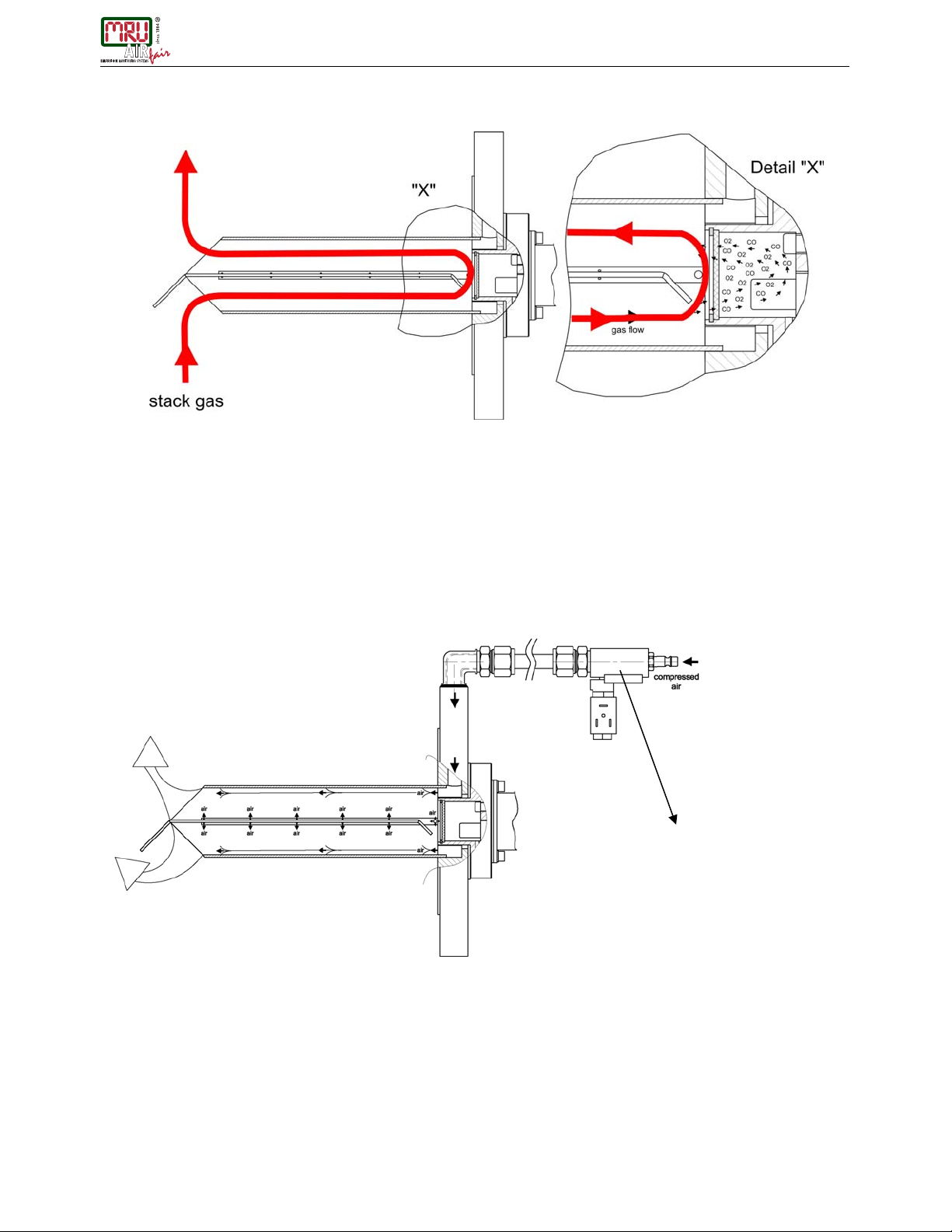
7.4 Principle of flow guidance tube
The construction of the sampling probe is using the flow guidance principle
The tube is divided in half by a metal plate welded into the middle of the tube.
The probe is mounted on the stack by means of an 8-hole flange (ANSI 4”, 150 lbs or DN100). The tip of the divider plate is ori-
ented facing towards the flow, which directs the stack gas into and through the tube at the same velocity as the flow in the stack.
The detector body is mounted on the flanged side of the tube through a hole in the flange cut for that purpose. In the body, behind
a filter screen (the measuring side of detector), the two sensors for oxygen and combustibles are exposed to the stack gas flowing
through the filter screen. In the detector behind the sensors, ambient air for reference gas diffuses through another filter screen
(for dust protection) and flushes the backside of sensors (the reference side of the detector).
Illustration for compact probe only
The flange feeds compressed air to several holes placed strategically around the detector and through a small tube, with air-
releasing orifices spaced along its entire length, which is mounted along the metal plate in the center of the probe. The timing,
duration and number of pulses of compressed air is controlled by user-settable electronic parameters and released by a solenoid
valve. During purging, compressed air blows across the filter screen protecting the sensors, and from the holes in the tiny blow-
back tube in the center of the probe, dislodging any accumulation of particulates so they will flow freely out of the probe and back
into the stack.
blowback in the stack
back-purge solenoid valve
www.GlobalTestSupply.com
Find Quality Products Online at: sales@GlobalTestSupply.com

OPERATING MANUAL OXYGEN MONITORING SYSTEM OMS 420
17
7.5 Transmitter electronics
The transmitter is housed in an aluminum enclosure (IP65, NEMA4X) that contains:
•Printed circuit board with u-processor (PCB “MAIN”)
•Backlit, graphic display and dust proof keypad
•Printed circuit board for the sensor connection (PCB “OMS”)
•Electrical connector for power supply and data transfer
„
MAIN“
p
cb
(
2
)
„OMS“ pcb (1)
www.GlobalTestSupply.com
Find Quality Products Online at: sales@GlobalTestSupply.com

OPERATING MANUAL OXYGEN MONITORING SYSTEM OMS 420
18
7.6 Manual calibration
To perform calibration of the instrument, the user can use following schematic diagram (or similar).
It is required to use moistured calibration gas (see § 4.7) and two hand-ball valves to select between instrument air (zero gas) and
calibration gas (span gas) supply to calibration inlet port of unit.
The procedure of calibration is described in chapter § 6.7.
7.7 Recommended calibration gas
For automatic calibration or manual calibration (see procedure in chapter 6.7.3) customer shall use following calibra-
tion gases:
1) zero gas = instrument air (21 %O2, 0 ppm HC)
2) span gas = 2…3 %O2; 400…600 ppm CO ; 40…60 ppm H2; rest N2
Note: It is highly recommended to use water bubblier to moisture the calibration gas!!!
Manual calibration
www.GlobalTestSupply.com
Find Quality Products Online at: sales@GlobalTestSupply.com

OPERATING MANUAL OXYGEN MONITORING SYSTEM OMS 420
19
8 Software flow chart
www.GlobalTestSupply.com
Find Quality Products Online at: sales@GlobalTestSupply.com

OPERATING MANUAL OXYGEN MONITORING SYSTEM OMS 420
20
9 Operation
9.1 Start-up
Prior to start-up, use the following check list to verify that all conditions are set for proper start-up:
Checklist transmitter
•Transmitter removed from the probe? (Note: always power up with transmitter removed from the probe/stack!!)
•Cast cover closed and screwed on?
•Transmitter easily accessible and visible?
•Ambient temperature around transmitter electronics in operating range of 0 °F to 140 °F (-20°C to 60 °C)?
•Correct location of transmission cable (not in close proximity to high power supply cables or engines)?
•Connection for power supply connected properly?
•Signal connection connected properly?
•Power supply (factory provided line power fuse) switched on?
•Start up considerations:
Wiring
: Most problems are due to incorrect wiring. Please double check the wiring.
Shield should be grounded only at one side of the cable.
Leaks:
Check the calibration inlet port plug for correct fit.
Insulation:
Check that the mounting flange has been properly insulated to prevent gas condensation.
Temperature:
Check mounting flange temperature: min. 160 °F (70 °C) and max. 300 °F (150 °C).
Check ambient temperature of transmitter for max. 100 °F (+60 °C).
Note: If flange temperature at site with mounted probe and transmitter is below
160 °F
(70 °C)
it is necessary to use a flange heater (ask MRU) to prevent condensation!!!
After power is switched on, the MRU logo and model of the unit will be displayed!
9.2 Warm-up
Warm-up time: minimum 30 minutes
LCD will display a time count down for 30 minutes.
During warm-up, some inside measured values (heaters current and voltages) will be compared with credible thresholds and in
case of “out-of-range”, an error message will be displayed. After countdown, if everything is OK, the message will change from
“please wait” to the main measuring menu.
The “SKIP” function is used only for service purposes, to allow the operator to access other unit functions without waiting until the
end of warm-up interval time. During this time, measurement values are not credible.
During warm-up, all other menus (info, service and setting) are accessible.
www.GlobalTestSupply.com
Find Quality Products Online at: sales@GlobalTestSupply.com

OPERATING MANUAL OXYGEN MONITORING SYSTEM OMS 420
21
9.3 Main measuring menu
After warm-up, the unit will start automatically by displaying the main measurement menu.
O2real time value with 0.01% resolution
COereal time value with ppm resolution
Press “INFO” key for “info” menu (see chapter 9.4)
Press “SERV” key for “service” menu (see chapter 9.5)
Press “SET” key for “settings” menu (see chapter 9.6)
Press “CALIB” key for “calibration” menu (see chapter 9.7)
9.4 Info menu
In the “INFO” menu the following parameters can be called up from a scroll up/down list:
•Next back-purge in hours/minutes
•Next automatic set to zero in days/hours
•If the display shows „----„ the automatic set to zero is not activated
•Gas humidity display in % 1 - 25 or disabled
•O2value wet: The O2display is calculated to “wet“ (*)
dry: The O2display is calculated to “dry“(*).
The gas humidity can be set by “SET” to “Set gas humidity“
•4 - 20 mA 02setting range of analog O2output
•4 - 20 mA CO setting range of analog COe output
•Firmware installed firmware version
•Hardware installed hardware version
•Serial number display of the serial number
•O2sensor installed
•CO sensor installed/not installed
(*) Formula for O2calculation dry/wet
%97.20max2 =Ooxygen content in air
=wetO2measured O2-value in wet stack gas
=dryO2calculated (%) O2-value dry
=
H
water content (%) in stack gas, (value entered manually), ⎟
⎟
⎠
⎞
⎜
⎜
⎝
⎛−⋅= dryO wetO
H2
2
1100
therefore calculation of ⎟
⎠
⎞
⎜
⎝
⎛
−
⋅= H
wetOdryO 100
100
22
NOTE:
If between 30 min no button is
pressed during the measurement,
the level will be set on "0". I.e. the
menus SET and CALIB are only by
renewed PIN input usable.
www.GlobalTestSupply.com
Find Quality Products Online at: sales@GlobalTestSupply.com

OPERATING MANUAL OXYGEN MONITORING SYSTEM OMS 420
22
9.5 Service menu
Displays actual 6 lines from a scroll up/down list with measured (A/D converter) components information.
Press the “UP” or “DOWN” key and return back to main measuring menu by pressing “BACK”.
standardvalue alloweddeviation
O2cell - 10 mV (with operation temperature and 21 % O2) ± 5 mV
O2heater 12 V (depending on flange temperature) ± 2 V
O2heater 1,3 A (heater current) ± 0,3 A
CO cell 5 mV (after warm-up and with fresh air ) ± 10 mV
CO heater 7,5 V (depending on flange temperature) -3,0 V…. + 1 V
CO heater 0,4 A (heater current) ± 0,1 A
Unit temperature less then 160 °F (70 °C)
Typical mV-values for COe sensor:
O2= 3 %, CO = 200 ppm Æ98,0 mV
O2= 3 %, CO = 500 ppm Æ190,0 mV
O2= 10 %, CO = 200 ppm Æ32,0 mV
O2= 10 %, CO = 500 ppm Æ93,0 mV
If the system detects an error, the plain text meaning will be displayed after pressing “ERROR”
key
www.GlobalTestSupply.com
Find Quality Products Online at: sales@GlobalTestSupply.com
Table of contents
Popular Transmitter manuals by other brands


Geo
Geo Web Pack quick start guide

Inovonics
Inovonics EchoStream EN1210W installation instructions

IKONNIK
IKONNIK KA-6 quick start guide

Rohde & Schwarz
Rohde & Schwarz SR8000 Series System manual

Audio Technica
Audio Technica UniPak ATW-T93 Installation and operation

NIVELCO
NIVELCO EasyTREK SCA-300 Series Programming manual


