manuals.online logo
Brands
  1. Home
  2. •
  3. Brands
  4. •
  5. MSB Technology
  6. •
  7. Media Converter
  8. •
  9. MSB Technology Link DAC III User manual

MSB Technology Link DAC III User manual

Users Manual
The GOLD LINK DAC provides an unparalleled sound experience with virtually any
available digital source. Four internal stereo DA converters give improved signal-to-noise
and channel separation characteristics, providing outstanding signal quality to your
preamplifier.TheGold has little outputfiltering for the bestpossible sound, electromagnetic
shielding of all the key components and high performance, high slew rate operational
amplifiers. This DAC delivers incredible “focus” and depth of soundstage to the listening
environment.
MSB GOLD LINK DAC
(Full value LINK trade-in offered!) $1295
MSB Platinum Link DAC
MORE WAYS TO ACHIEVE
INCREDIBLE SOUND... FROM MSB
This 46 bit - 384 kHz sign magnitude R2R ladder DAC with four independent discrete
converters goes way beyond any other DAC. It can handle greater resolution and higher
samplingfrequencies than any existing format,for maximum S/N and channel isolation.The
Platinum upsamples lower sampling rate sources to 24 bit - 96 kHz. It has up to 5 digital
inputs (ATT glass, Toslink optical, Coaxial SP/DIF, Balanced AES/EBU and IEEE 1394
Firewire) as well as balanced and single-ended analog outputs. Selectable digital filter re-
sponse (interpolation and slope) give you complete control. The painstaking detail, care and
phenomenal sound you demand from a high-end DAC.
(Full value LINK or Gold LINK trade-in offered!) $3395
HIGH QUALITY, AFFORDABLE CABLE PRODUCTS
6 RCA to DB-25
Digital Audio
AC3-RF - for LD
Audio - Triple Shielded
S-Video - 2m
Video
Toslink Optical 1m - also 2m, 15m
Red Hawk Optical 1m - also 3m, 20m
MSB Custom Digital
$95
$35
$35
$45
$35
$35
$45
$95
call
The Nelson Upgrade (Factory Installed Only)
Amajor audiophile upgrade tothe LINK III, addinga professional balanced digital input,all
new analog output stage and beefed up power supplies. Must hear to believe! $485
Upsampling (User Installable)
MSB has created a way to upsample from ANY lower audio standard to 24 bit - 96 kHz.
Includes extra jitter reduction and back panel switch. $199
HDCD (User Installable)
Making the Link III HDCD compatible allows you to take full advantage of the benefits of
the HDCD format. Auto detection and front panel indicator. (Simultaneously works with
the Upsampling Upgrade) $199
192 kHz (User Installable)
In keeping with MSB’s goal of providing clients with the most up-to-date technology, the
Link III circuits are fully upgradable. As 192 kHz software and hardware becomes
available, we plan to offer an upgrade.
Virtual 3D (User Installable)
This upgrade allows those with two speaker setups to enjoy Pro Logic through a series of
digital filters that project five “virtual speakers” into space. $149
MSB Interconnects
Thankyoufor purchasing theworldfamous LINK DAC III. Iamsure
youwillbeverypleasedwith it. If you ordered anyoftheuserinstallable
upgradesfactoryinstalled,astorageandshippingboxisincludedforthe
upgradeincaseyou ever needtoreturnittous for service. Pleaseretain
theseboxes.
At least 100 hours of burn-in is required on this DAC. Custom-
ers generally recommend one month.
FrontPanel
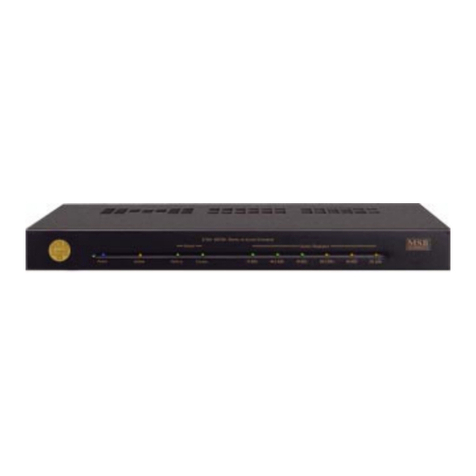
The front panel is quite simple with no user controls. LEDs indicate
power,theinput source, thesamplingfrequencyand whether anoption
isinstalledandisactive.
Power-Theblue power LEDlightsupany timepowerisapplied. The
LINKshouldalwaysbe left pluggedinwiththeblueLED lit.
Option-TheoptionLEDwillneverlightunlessan option is installed. It
indicatesaspecificfunctionforeachoption,suchasupsamplingorHDCD.
Itwilllightinthefullbrightnessandhalfbrightnessmodeforfurtherdif-
ferentiationbetweenmultiple options.
Source-Boththecoaxialand optical inputs areindicated onthe display
with separate LEDs. When an active digital signal is attached to the
LINKIIItheLEDwill light, evenifnomusicisplaying,or the sourceis
data(likeDolbyDigital orDTS). Ifbothsourcesare active, bothLEDs
willlight,buttheCOAXIALinputwilltakepriority. IfnoLEDislit,the
analogpass-throughisactive.
SampleFrequency- TheseLEDsindicatetheincoming samplingfre-
quency,whethermusic isplayingornot, and whetherthesourceis data
ornot.The 192 LED willnotlight without the192optioninstalled.
Operation
Theoperationof the LINKIIIisfully automatic.
Software
VirtuallyallPCMdigitalsourcescanbedecodedincluding24/96Kandin
thefuture witha small upgrade,192K (DVD-A). Thefrequency of the
incomingsignalisindicatedonthefrontpanelwithLEDs.Notethatmany
DVDplayersplay 96K-24 bitDVDsbut output at48kHz.Some players
offer a menuoption to select 96K but many do not. To get the true 96K
outputa96KdigitaloutputupgradeisavailablefromMSB. Discussionof
addingcopy protectionis underwayin an AES working group. Should
decryptionberequired to playbacknew software, anupgradeboardwill
beoffered atareasonable pricetoplug intotheLINKs upgradesockets.
Troubleshooting
No “Source” indicated - Check for bad cable, or cable plugged into the wrong
output on the transport.
No sound - Check that source is valid audio source. Change to a standard CD just
to be sure. Check that analog outputs are connected to the “outputs” not the
“inputs”.
Still no sound - connect an analog output from the source directly to the volume
control. Verify that the rest of the system is working. Now move the same analog
output to the analog input on the LINK. Add a new cable from the analog output to
the volume control. Disconnect the digital inputs and confirm that the system still
works. Now plug in a digital source. You should hear a click and the front LEDs
should light.
KeySpecificationsTHD+N (0dBFS, 1kHz) = -96dB,
DynamicRange (-60dBFS,1kHz) = -106dB
SignaltoNoise(Digital zero withnomuting)=-106dB
Warranty
All MSB products carry a one year warranty. No returns accepted without an RMA.
Uponreceipt, MSB will repairor replace anydefective product. All product shipped
FOB La Honda. Shipping is the responsibility of the consignee.
27
LINKIII Back Panel
Thebackpanel containstheinterfaceconnectors andonetoggleswitch.
Toggle Switch - On a LINK III with no options installed, the toggle
switchperforms adigital phaseinvert. The switchdown isthe normal
phase. Placingthe switch up will invert the phase. Thisswitch canbe
usedto activatecertainoption boardsaswell.
AnalogAudio Input- The analoginput providesa highquality pass-
throughswitchingfeaturethathasmanyapplications.In other words, the
pass-throughconnectionsaremadeunlessadigitalinputisactive.Active
meansthatthesourcepluggedin is powered on,butnotnecessarilyplay-
ing.Thisfeaturecanbechanged to only switchwhennonzerodigitalsig-
nalsarepresent.Inthis case theanaloginputisonlyinterruptedwhen the
digitalsourceisplaying,notjustturnedon. This option isspecifically de-
signed for use with C and Ku satellite receivers such as the 4DTV re-
ceiver. Toconfigurethis option,seethe setup section.
AnalogAudio Outputs-The LINKIII outputs astandard 2VRMS at
0dB. The outputimpedance is330 ohms.
DigitalInputs-BothaToslink optical andCoaxialDigitalaudioinputis
provided.Autodetectionselectseither active input.Ifbothareactive,the
Coaxialinputisselected.ActiveinputsareindicatedwithfrontpanelLEDs.
Ablanklocationisprovidedfor installation of anXLRconnector,part of
theNelson and192 kHzupgrades.
Power-TheLINK uses anoutboardpowersupply, withatleast+8VDC
and +/- 15VDC. The LINK contains no fuses to replace, but instead
containshigh-performanceresettablefuses.Theyallow the unit toreturn
tonormal after anoverload condition. TheLINK is designedto operate
continuously,andshouldbelefton at alltimes.
DSP Headers 1
2
3
4
5
6
7
8
J18 J19
123456789
123456789
123456789
1
2345678
9
123456789
1234567890
1
23456789
0
1234567890
1234567890
1
23456789
0
1234567890
1234567890
1234567890
1234567890
1
23456789
0
1234567890
Ground
Data
BitClock
L/RClock
M Clock
DataFlag
Ground
Ground
S/PDIF
S/PDIF(inverted)
Ground
DigitalActive
Option1
192kHz
Ground
123456789
1
2345678
9
123456789
123456789
1
2345678
9
123456789
NORMAL POSITION OF LINK III JUMPERS
3
1
2
3
4
5
6
7
8
J16
1234567890
1
23456789
0
1234567890
1234567890
1
23456789
0
1234567890
1234567890
1
23456789
0
1234567890
1234567890
1234567890
Ground
LFilter1
LFilter2
Ground
RFilter1
RFilter2
Ground
+8V, -8V
AnalogFilterChange
Theanalog filtersin the outputstage canbe adjusted. The normalcon-
figurationcomplieswiththecommonpracticeofratherheavilyfilteringthe
outputsto achieveperfectmeasurements. For thosewho prefer greater
dynamicsandattack,try removing thejumpersfrompositions2and 5 of
J16. Theycan beplaced onpositions 1and 4for safekeeping.
1
2
3
4
5
6
7
8
J16
123456789
1
2345678
9
123456789
1234567890
1
23456789
0
1234567890
123456789
1
2345678
9
123456789
1234567890
1234567890
Ground
LFilter1
LFilter2
Ground
RFilter1
RFilter2
Ground
+8V, -8V
NORMAL FILTERS REDUCED FILTERING
6
OtherOptions
HeadersJ18 and J19 are for the upgradeboards alsosold byMSB (see
backpage). The standardjumper positionsare shown below for refer-
ence. Anymissingjumperswill preventtheLINKIIIfrom working.
45
$299
PowerSupply Upgrades
Theperformanceof the LINKcanbe improved withalargerpower sup-
ply. The MSB P1000 is designed as an add-on to the LINK III.
ConfigurationOptions
Inside the LINK III are several headers with jumpers installed. They
change various functions of the LINK III and allow upgrades to be in-
stalled. Several options can be set by the user including phase invert,
digitalzeroswitchingandamodificationtotheanalogfilter.
Openingthe LINKIII
Placethe LINKIII ona soft surfacelike atablecloth orcarpet. Discon-
nect the power supply. Remove the three philips screws on the back
edge of the cover. Turn the LINK over and remove the three philips
screwsfromthefront edge ofthecover. Carefullyseparatethe base from
the cover. Pick up the base and flip it over, placing it inside the cover.
Takecarenot todisconnectthe ribbon cabletothe frontpanel. Placethe
LINKsothatthe RCA connectorsarefacingAWAYfromyou. Thisway
allthediagramswillbe oriented correctly.
PhaseInvert
Phase invert is normally switchable with the toggle switch on the rear
panel. Phaseinvert canbe permanently setinside theLINK III instead.
Locatetheheader labeled J14. Removetheswitchand place ajumperas
shown.
J14
1234567890
1
23456789
0
1234567890
1234567890
1234567890
ZeroOption
Data
Data(inverted)
L/RClock
Reset
Ground
DataFlag
J14
123456789
1
2345678
9
123456789
123456789
1
2345678
9
123456789
ZeroOption
Data
Data(inverted)
L/RClock
Reset
Ground
DataFlag
J14
123456789
1
2345678
9
123456789
1234567890
1
23456789
0
1234567890
ZeroOption
Data
Data(inverted)
L/RClock
Reset
Ground
DataFlag
NORMAL PHASE INVERTED PHASE
DigitalZeroOption
Theanalogbypassis normallyinterruptedwhen adigitalinput is active.
Activemeansthatthe source pluggedinisturnedon,notnecessarilyplay-
ing,butjustpoweredon.This feature can be changedtoonlyswitchwhen
nonzero digital audio signals are present. It will ignore data such as
DolbyDigitalandDTSsignals. Inthiscasetheanaloginputisonly inter-
ruptedwhen the digitalsourceis playingvalidaudio, notjustturned on.
RemovethefirstjumperonJ14labeled“ZeroOption”. Thejumpermay
beplaced onjustone pinforfuture use.
J14
1234567890
1
23456789
0
1234567890
123456789
1
2345678
9
123456789
ZeroOption
Data
Data(inverted)
L/RClock
Reset
Ground
DataFlag
NORMAL SWITCHING ZERO OPTION SWITCHING

Other MSB Technology Media Converter manuals

MSB Technology The Select DAC User manual

MSB Technology

MSB Technology The Select DAC User manual

MSB Technology Select DAC II User manual

MSB Technology

MSB Technology Select DAC II User manual

MSB Technology Analog DAC User manual

MSB Technology

MSB Technology Analog DAC User manual

MSB Technology Signature DAC V User manual

MSB Technology

MSB Technology Signature DAC V User manual

MSB Technology DAC IV plus User manual

MSB Technology

MSB Technology DAC IV plus User manual

MSB Technology Universal Media Transport plus User manual

MSB Technology

MSB Technology Universal Media Transport plus User manual

MSB Technology Platinum LINK DAC User manual

MSB Technology

MSB Technology Platinum LINK DAC User manual

MSB Technology Platinum Studio ADC User manual

MSB Technology

MSB Technology Platinum Studio ADC User manual

MSB Technology Gold Link Dac III User manual

MSB Technology

MSB Technology Gold Link Dac III User manual

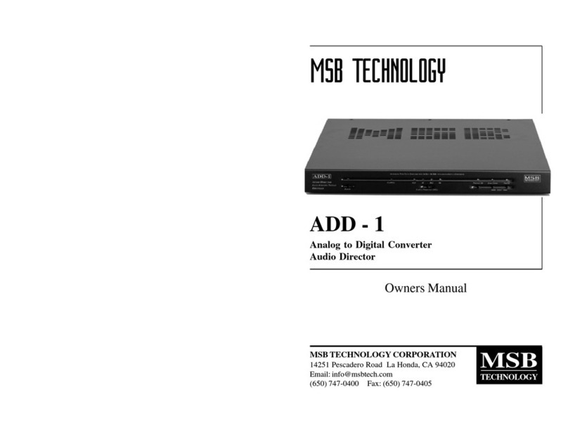
MSB Technology Nelson LINK DAC III User manual
MSB Technology

MSB Technology Nelson LINK DAC III User manual

MSB Technology Premier User manual

MSB Technology

MSB Technology Premier User manual

MSB Technology The Reference DAC User manual

MSB Technology

MSB Technology The Reference DAC User manual

MSB Technology Link DAC III User manual

MSB Technology

MSB Technology Link DAC III User manual

MSB Technology The Select DAC User manual

MSB Technology

MSB Technology The Select DAC User manual

MSB Technology ADD-1 User manual

MSB Technology

MSB Technology ADD-1 User manual

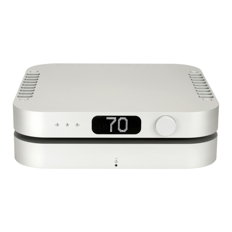
MSB Technology Diamond DAC IV User manual
MSB Technology

MSB Technology Diamond DAC IV User manual

Popular Media Converter manuals by other brands

Lindy 32159 user manual

Lindy

Lindy 32159 user manual

GRASS VALLEY 8943FC instruction manual

GRASS VALLEY

GRASS VALLEY 8943FC instruction manual

Bosch VG4-SFPSCKT installation manual

Bosch

Bosch VG4-SFPSCKT installation manual

Rohm BD9F500QUZ-EVK-001 user guide

Rohm

Rohm BD9F500QUZ-EVK-001 user guide

KYLAND Technology KGW3102 Series Hardware installation manual

KYLAND Technology

KYLAND Technology KGW3102 Series Hardware installation manual

Microchip Technology MCP1640 user guide

Microchip Technology

Microchip Technology MCP1640 user guide

Transition Networks FXC1115T user guide

Transition Networks

Transition Networks FXC1115T user guide

AJA OG-Hi5-4K-Plus Installation and operation guide

AJA

AJA OG-Hi5-4K-Plus Installation and operation guide

Crystal Vision ARC102 user manual

Crystal Vision

Crystal Vision ARC102 user manual

inogeni SHARE2 user guide

inogeni

inogeni SHARE2 user guide

Bel Canto e.One series user guide

Bel Canto

Bel Canto e.One series user guide

Siko ProTool SGH50 Translation of the original installation instructions

Siko

Siko ProTool SGH50 Translation of the original installation instructions

Hubner Baumer POG 90 Mounting and operating instructions

Hubner

Hubner Baumer POG 90 Mounting and operating instructions

Dexin NDS3558A user manual

Dexin

Dexin NDS3558A user manual

Motrona PU202 operating manual

Motrona

Motrona PU202 operating manual

CE-Link HCD0101 user manual

CE-Link

CE-Link HCD0101 user manual

Korg electribe owner's manual

Korg

Korg electribe owner's manual

MuxLab 500044 Quick installation guide

MuxLab

MuxLab 500044 Quick installation guide

manuals.online logo
manuals.online logoBrands
  • About & Mission
  • Contact us
  • Privacy Policy
  • Terms and Conditions

Copyright 2025 Manuals.Online. All Rights Reserved.