MSD 2760 User manual

MSD • WWW.MSDPERFORMANCE.COM • (915) 855-7123 • FAX (915) 857-3344
ONLINE PRODUCT REGISTRATION: Register your MSD product online. Registering your product
will help if there is ever a warranty issue with your product and helps the MSD R&D team create
new products that you ask for! Go to www.msdperformance.com/registration.
MSD Atomic Transmission Control Module
PN 2760
Thank you for purchasing the MSD Atomic Transmission Control Module (TCM). MSD is pleased
to announce that this transmission controller was designed with performance reliability, practicality,
and ease of use in mind. Using the correct adapter harness, this unit will plug directly into the factory
connectors on 4L60E/4L70E/4L80E GM transmissions, or the Ford AODE, 4R70W/E, 4R75W/E, E4OD,
and 4R100 transmissions. The Atomic TCM was designed to work as a stand-alone transmission
controller. Programming the transmission controller is done through the handheld monitor, which
eliminates the need for a computer to program the transmission controller.
As with any performance product, please be sure to read the entire instruction manual before
attempting to install this system on your vehicle. Please contract our customer support department
at (915) 855-7123 if you have any question about installing or operating the transmission controller.
Parts Included:
1 - AtomicTransmission Control Module
1 - Handheld monitor
1 - 4G Micro SD Card
Parts required but not included:
Transmission Harnesses
(only transmission specific harness is needed)
PN 2770 - 4L6XE (1992+) / 4L7XE (2006-on) / 4L8XE
(1993+) harness
PN 2771 - 4L7XE (2009+) harness
PN 2772 - Ford 4R7XW/E (1998+) harness
PN 2773 - Ford AODE/4R70W/E (1992-1997) harness
PN 2774 - Ford 4R100 (1998+) harness
PN 2775 - Ford E4OD (1995-1997) harness
PN 2776 - Ford E4OD (1989-1994) harness
ATOMIC TRANSMISSION CONTROL MODULE INSTALLATION
It is important to select a proper mounting location for the
TCM. The unit can be mounted in the interior or the engine
compartment as long as it is away from direct heat sources.
It is not recommended to mount the unit in an enclosed
area, such as the glove box. When a suitable location is
found, make sure all wires reach their connections. Use the
TCM as a template and mark the location of the holes. Use
a size #20 drill bit to prepare for the supplied self tapping
screws. Assemble the sleeves in the TCM (Figure 1).
Note: Mounting this module near headers or high heat
sources may affect the operation of the TCM.
Figure 1

2 INSTALLATION INSTRUCTIONS
MSD • WWW.MSDPERFORMANCE.COM • (915) 855-7123 • FAX (915) 857-3344
Pin
2
1
1
2
3
4
5
6
7
8
9
10
11
12
Color
Brown
White
Brown
Black
Gray
Dark Blue
Green
Ta n
Red
Orange
Lt. Blue
Pink
White
Yellow
Function
Ground
Signal
Overdrive Cancel (Ford Applications Only)
TPS Ground Reference
Calibration Select
Manual Bump up / Manual Mode Select
TCC Lock
Speed Out
TCC Unlock
TPS 5V
Manual Bump Down
12V Ignition in
RPM/Tach In
TPS Signal In
CONNECTOR
VSS
CONNECTOR
Transmission GT Series 12 Pin
BRAKE ON/OFF (TCC UNLOCK)
TCC LOCK
AUTO/TO MANUAL MODE, MANUAL BUMP UP
MANUAL BUMP DOWN
SPEED OUT
CAL A/B SELECT
OVERDRIVE CANCEL (FORD ONLY)
BATTERY (-)
POWER
BATTERY (+)
T
C
RANSMISSION
ONTROL
TPS IN (0-5VDC)
5V
TPS GROUND
TACH INPUT (RPM)
12V SWITCHED (IGNITION)
12 PIN - JAE CONNECTOR
SOLD SEPARATELY
(NOT INCLUDED IN THIS KIT)
TRANSMISSION ADAPTER HARNESSES
PN 2770 - 4L6XE / 4L7XE / 4L8XE
PN 2771 - 4L7XE (2009+)
PN 2772 - Ford 4R7XW/E (1998+)
PN 2773 - Ford AODE/4R70W/E (1992-1997
)
PN 2774 - Ford 4R100 (1998+)
PN 2775 - Ford E4OD (1995-1997)
PN 2776 - Ford E40D (1989-1994)
Figure 2
WIRING

INSTALLATION INSTRUCTIONS 3
MSD • WWW.MSDPERFORMANCE.COM • (915) 855-7123 • FAX (915) 857-3344
BROWN (OVERDRIVE CANCEL): (FORD ONLY) Toggles Overdrive function on/off with momentary
connection to 12v(+) or ground(-).
BLACK (TPS GROUND REFERENCE): Connect to ground reference on throttle position sensor (TPS).
GRAY (CALIBRATION SELECT): Switch to ground to select Calibration B. In race applications
Calibration B can be used for aggressive shift characteristics. In 4x4 applications Calibration
B is used as a shift point compensation using the Transfer Ratio (INITIAL SETUP) setting to
compensate for transfer case reduction ratio in AUTOMATIC shift mode. Connect to a switched
ground to activate.
BLUE (MANUAL BUMP UP / MANUAL MODE SELECT): Momentarily switch to ground for 3 seconds
to activate MANUAL MODE. Once in MANUAL MODE, momentarily switch to ground to
UPSHIFT.
GREEN (TCC LOCK): Switch to ground to lock Torque Converter Clutch in 2nd-4th gear regardless
of vehicle speed.
TAN (SPEED OUT): Speedometer signal output (12v square wave; 20,000 pulses per mile).
RED (TCC UNLOCK): Switch to 12v to unlock Torque Converter Clutch. Normally connected to brake
pedal switch to unlock TCC when brakes are applied.
Note: This function will prevent the TCC from locking under any operating condition while
activated with 12v.
ORANGE (TPS 5V): Connect to 5v reference on throttle position sensor (TPS).
LT. BLUE (MANUAL BUMP DOWN): Once in MANUAL MODE, momentarily switch to ground to
DOWNSHIFT.
PINK (12V IGNITION IN): Connect to switched ignition 12v source.
WHITE (RPM/TACH IN): Connect to tach output on MSD Ignition or coil (-) on inductive ignition.
Note: Will accept 5V(+) used to trigger GM LS coil packs.
YELLOW (TPS SIGNAL IN): Connect to TPS sensor signal.
ATOMIC TCM HANDHELD MENU
SELECT PRODUCT: The Atomic TCM handheld will connect
to the TCM, and allow user changes to the TCM display
setup (Figure 3).
DISPLAY SETUP: The Display Setup controls the look of the
handheld unit and the Firmware version. (Figure 3).
LCD CONTRAST: Adjust the contrast on the LCD screen.
Using the joystick, the brightness level can be adjusted
up or down in 5% increments (Figure 3).
WIRING (FIGURE 2)
Figure 3

4 INSTALLATION INSTRUCTIONS
MSD • WWW.MSDPERFORMANCE.COM • (915) 855-7123 • FAX (915) 857-3344
BACKLIGHT LEVEL: Adjust the brightness of the screen.
The brightness can be adjusted up or down using the
joystick in five percent increments (Figure 4).
DISPLAY UNITS: Display items in either English (inches,
Fahrenheit, MPH) or Metric (mm, Celsius, KPH) (Figure 4).
USER MODE: Used for changing parameters in Atomic LS EFI
systems. This setting doesn’t change any menus in the
Atomic TCM (Figure 4).
FIRMWARE VERSIONS: Displays Transmission Control
Module and handheld programmer Firmware versions
(Figure 4).
Figure 4

INSTALLATION INSTRUCTIONS 5
MSD • WWW.MSDPERFORMANCE.COM • (915) 855-7123 • FAX (915) 857-3344
ATOMIC TCM HANDHELD MENU
TCM DASH: Eleven parameters are displayed in real-time:
CAL SELECT, ENGINE RPM, SPEED, TPS, FLUID TEMP,
PCS DUTY CYCLE , SHIFT POS., GEAR, TCC LOCKED,
SHIFT MODE, and DTC COUNT (Figure 5).
Refer to the table labeled TCM DASH for a complete description
of each parameter in the Atomic Dash (Figure 5).
TCM GAUGES: Displays RPM, TPS, TFT, MPH, Commanded
Gear, Shifter Position, Active Calibration, Mode, and TCC
Status in real time gauge format. THIS SCREEN IS NOT
CONFIGURABLE (Figure 5).
INITIAL SETUP: The basic controller input parameters; which
must be configured prior to vehicle operation.
ADVANCED SETUP: Advanced program settings for optional
features and optimized drivability (Figure 5).
INITIAL SETUP
Note: In order for changes to INITIAL SETUP parameters to be
stored in memory, the Atomic TCM must be powered off
for at least three (3) seconds prior to subsequent power-up
and operation. Upon power-up, it is a good idea to check
and make sure the new parameters appear as expected
BEFORE attempting vehicle operation.
TRANS TYPE: Selection menu for transmission type. Choic-
es include the following (Figure 6):
GM: 4L6XE (Early93+), 4L7XE (2009+), 4L8XE (1992+)
Ford: AODE 1992-1995, 4R70W/E 1993-1997, 4R70W/E
1998+, E4OD 1989-1997, and 4R100 1998+
Note: Both the early model Ford Manual Lever Position Sensor
(MLPS) and later model Digital Transmission Range (DTR)
sensors are supported. The controller automatically
detects the type of range sensor connected; however,
the proper harness is required to interface with the type
of sensor used.
CYLINDER SELECT: Configure the pulse count for the
tachometer signal input. Configurable from 1-12 cylinder.
Settings available include 1, 2, 4, 6, (2 settings for 6 odd &
1 setting for 6 even fire), 8, 10, and 12 cylinders (Figure 6).
Note: GM LS applications should be set to 1 CYL if tach signal
wire is connected to 5v trigger on single coil pack.
Ford Mod Motor applications (Coil On Plug) should be
set to 1 CYL if tach signal wire is connected to coil(-) on
single coil.
Ford Mod Motor applications (Dual coil pack) should
be set to 2 CYL if tach signal wire is connected to either
coil(-) on one coil pack.
REAR END RATIO: Selection menu for rear end gear ratio.
Adjustable from 1.00 to 10.00 in .01 increments (Figure 6).
Figure 5
Figure 6

6 INSTALLATION INSTRUCTIONS
MSD • WWW.MSDPERFORMANCE.COM • (915) 855-7123 • FAX (915) 857-3344
TRANSFER RATIO: Selection menu for transfer case gear
ratio. Adjustable from 0.50 to 10.00 in 0.01 increments.
Leave this value set to the default (1.00) unless the
vehicle is equipped with a transfer case. NOTE:
Changes made in this menu selection only apply to
Calibration B (grey activation wire) (Figure 7).
TIRE HEIGHT: Selection menu for tire height (in inches).
Adjustable from 15.00 to 72.00 inches in 0.01-inch
increments (Figure 7).
MAX SHIFT RPM: Selection menu for setting the maximum
Engine RPM allowed before the controller forces
an automatic upshift. Adjustable from 800RPM to
10,000RPM (Figure 7).
Note: This MAX SHIFT RPM applies primarily to automatic
shifts when operating in the Overdrive (OD) or Drive
(D) range. However, when operating in Manual Mode,
the controller will automatically force an upshift if
engine RPM exceeds the max shift RPM for more
than 0.5 seconds.
CALIBRATE TPS: Calibration menu for a standalone TPS
signal input. Default selection is “NO.” To start a
calibration turn the key on, but keep the engine off.
Using the joystick, toggle the selection to “YES”
and press the joystick down in the center. This will
start a 5 second calibration timer. Once the count
down begins, depress the accelerator pedal to the
Wide Open Throttle (WOT) position and release. The
handheld should display a calibration successful
message. If the calibration was unsuccessful, repeat
the calibration process (Figure 8).
Figure 7
Figure 8

INSTALLATION INSTRUCTIONS 7
MSD • WWW.MSDPERFORMANCE.COM • (915) 855-7123 • FAX (915) 857-3344
ADVANCED SETUP
Note: Changes to Calibration A and Calibration B parameters
(SHIFT MULTIPLIER, TCC MULTIPLIER, and FIRMNESS
MULTIPLIER) take effect in real time and do not require
power cycling of the Atomic TCM in order to be committed
to memory.
Changes to all other ADVANCED SETUP parameters require that
the Atomic TCM be powered off for at least three (3) seconds prior
to subsequent power-up and operation. Upon power-up, it is a
good idea to check and make sure the new parameters appear
as expected BEFORE attempting vehicle operation.
CALIBRATION A/B: The Atomic TCM supports two calibration
modes. Calibration A is enabled by default and can be
considered a street or daily driven calibration. Calibration
B can be used for racing, off road, or aggressive shifting
settings. When the grey wire is grounded, Calibration B
is enabled. When Calibration B is enabled, the setting
under Transfer Ratio (INITIAL SETUP) is factored into the
shift strategies to accommodate the additional gearing in
off road applications. If the vehicle isn’t equipped with a
4X4 transfer case, leave the Transfer Ratio setting at the
default setting of 1.00 (Figure 9).
Note: It is recommended to connect a micro-switch to the transfer
case shifter in off-road applications. This will switch into
calibration B automatically when the transfer case is
engaged.
Note: Calibration A/B swaps are inhibited while the vehicle is
moving. To effect an A/B cal swap using the grey wire,
vehicle speed (VSS) must be zero (0).
SHIFT MULTIPLIER: Selection menu for scaling automatic
upshift / downshift speeds (MPH). The multiplier range
is 0.75 to 1.50 in 0.01 increments. Increasing the SHIFT
MULTIPLIER above the default value (1.00) raises the
upshift and downshift speed for a given TPS value.
Decreasing the SHIFT MULTIPLIER below the default value
(1.00) lowers the upshift and downshift speed for a given
TPS value (Figure 9).
TCC MULTIPLIER: Selection menu for scaling Torque Converter
Clutch (TCC) lock and unlock speeds (MPH). The
multiplier range is 0.75 to 1.50 in 0.01 increments.
Increasing the TCC MULTIPLIER above the default value
(1.00) raises the lock and unlock speed for a given TPS
value. Decreasing the TCC MULTIPLIER below the default
value (1.00) lowers the lock and unlock speed for a given
TPS value (Figure 9).
Figure 9
FIRMNESS MULTIPLIER: Selection menu for adjusting part throttle shift firmness. The multiplier range
is 0.80 to 2.00 in 0.01 increments. Increasing the FIRMNESS MULTIPLIER above the default value
(1.00) increases part throttle shift firmness. Decreasing the FIRMNESS MULTIPLIER below the
default value (1.00) decreases part throttle shift firmness. WOT shifts occur at maximum firmness
and are not affected by this multiplier (Figure 9).
Warning: Decreasing the FIRMNESS MULTIPLIER value will result in lower line pressure at
part throttle conditions – resulting in possible slippage and damage to internal transmission
components. Used or worn transmissions will be more susceptible to damage sustained while
operating with insufficient line pressure.

8 INSTALLATION INSTRUCTIONS
MSD • WWW.MSDPERFORMANCE.COM • (915) 855-7123 • FAX (915) 857-3344
WOT THRESHOLD: (Wide Open Throttle) The Atomic TCM
module utilizes a MPH/KPH shifting strategy. When the
throttle position exceeds the WOT Threshold setting, the
TCM will switch to an RPM shifting strategy, and will upshift
automatically when the ENGINE RPM reaches the MAX
SHIFT RPM (set in the Initial Setup menu). Adjustable from
0% to 100% in 1% increments (Figure 10).
VSS PULSE PER REV: Vehicle Speed Sensor pulses-per-revolution
selection menu. Default values (and reluctor locations) are
as follows (Figure 10):
All GM Transmissions: 40 Pulses per Rev (Located on
Transmission Output Shaft)
Ford AODE, Early 4R70W/E: 6 Pulses per Rev (Integral to
Forward Drum)
Ford Late 4R7XW/E: 6 Pulses per Rev (Integral to Forward
Drum), some applications may be 24 Pulses per Rev.
Ford E4OD: 108 Pulses per Rev (Between Ring Gear and
Carrier in Rear End)
Ford 4R100: 6 Pulses per Rev (Located on Transmission
Output Shaft) Diesel transmissions may be 18 Pulses per
Rev.
Ford Speedometer Transmitter: 4 Pulses per Rev (This
"hybrid" transducer had both a mechanical cable drive and
2-pin electronic Vehicle Speed Sensor (VSS) Output. An
example is Dorman Part Number 917 614.)
Note: Default values can be changed from this screen to
accommodate a custom reluctor tooth count or inaccurate speedometer reading. The speedometer
can be checked for accuracy with a GPS, if any inaccuracy is found, adjust the Pulse per Rev
until speed in the dash is reporting an accurate vehicle speed.
DYNO MODE: ENABLE/DISABLE: Dyno mode is intended for use when operating the vehicle on a
chassis dyno. Enabling Dyno Mode will force the earliest possible upshifts until the transmission
is in direct (3rd gear). Once in third gear, the transmission controller will prevent downshifts under
increased throttle opening – up to, and including, WOT. This feature enables dyno pulls to be
made without the possibility of an unintentional downshift. Dyno Mode will also lock the Torque
Converter Clutch (TCC) when the vehicle speed equals (or exceeds) 30 mph. The transmission will
follow a closed-throttle downshift and TCC unlock schedule
when Dyno Mode is enabled. Dyno Mode can be disable
manually from this screen, or it will automatically be disabled
if power to the transmission controller is cycled off (i.e. run
through a key off cycle) (Figure 10).
Note: Dyno Mode Enable is inhibited when vehicle speed is equal
to, or greater than, 50 MPH. When attempting to enable Dyno
Mode, be sure the vehicle speed is less than 50 MPH.
DIFF MOUNTED VSS: Default value is “NO”. When selecting the
Ford E4OD transmission, this value may need to be changed
to “YES”. 1992-96 E4OD applications used the Rear Anti-Lock
Brake Sensor (RABS) for vehicle speed sensing. The tone
ring is located in the rear differential between the ring gear and
carrier. If using an E4OD in a vehicle utilizing a different VSS
/ reluctor configuration (i.e. on the driveshaft or transmission
output shaft), select “NO”. Failure to configure this parameter
correctly with an application using the RABS VSS will result
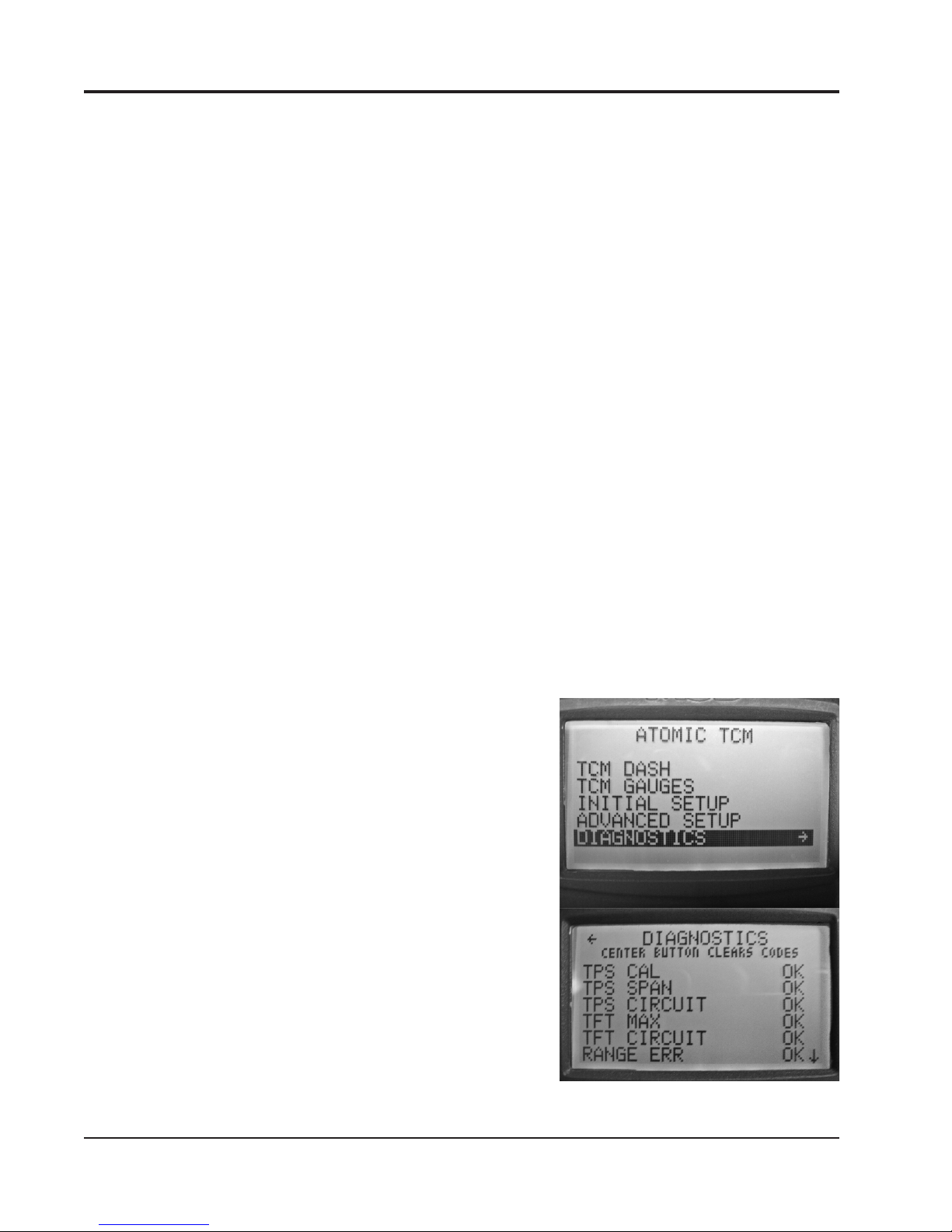
in the Atomic TCM computing speed incorrectly (Figure 11).
Figure 10
Figure 11

INSTALLATION INSTRUCTIONS 9
MSD • WWW.MSDPERFORMANCE.COM • (915) 855-7123 • FAX (915) 857-3344
LOAD DEFAULTS: This selection resets the Transmission Control Module back to default settings. Toggle
from “NO” to “YES” using the joystick on the hand held. Then press down on the joystick in the
center. This setting is useful for installing the transmission control module on another transmission
or for troubleshooting.
Note: MSD recommends loading the Atomic TCM defaults after performing a software update.
TCM DASH AND GAUGE PARAMETERS (FIGURE 12)
Engine RPM Displays Engine Speed (Revolutions per Minute)
SPEED Displays Vehicle Speed (Miles per Hour/Kilometers per Hour)
TPS Displays Throttle Position Sensor (0 @ idle – 100 @ Wide Open Throttle)
Fluid Temp Displays Transmission Fluid Temperature (°F or °C)
PCS DC Displays Pressure Control Solenoid Duty Cycle (Higher number indicates lower
line pressure, Zero indicates maximum line pressure)
SHIFT Displays Shifter Position
GEAR Displays Commanded Gear
CAL SELECT Displays active calibration (“A” or “B”)
MODE Displays “A” for Auto and “M” for Manual
TCC Status Displays “L” when TCC is locked (no character present when TCC is unlocked)
Figure 12
CAL SELECT
MODE
TCC STATUS

10 INSTALLATION INSTRUCTIONS
MSD • WWW.MSDPERFORMANCE.COM • (915) 855-7123 • FAX (915) 857-3344
OPERATIONAL NOTES AND SAFEGUARDS: The following section describes some of the Atomic
TCM’s built-in safeguards, as well as operational notes:
Shifter Position Error: In the event that the Atomic TCM cannot recognize a valid signal from the
transmission’s Range Switch, and translate it to a corresponding shifter position, “ERROR” will be
displayed on the handheld in the SHIFT POS field. If the cause is intermittent, the “ERROR” message
will clear and normal operation will resume. If the error is persistent, the transmission can be operated
in its OEM limp mode (i.e. Park, Reverse, Neutral, and 2nd or 3rd – depending on the transmission
model and OEM limp mode strategy).
Excessive Transmission Fluid Temperature (TFT): If, at any point during operation, the Transmission
Fluid Temperature exceeds 266°F, the Atomic TCM will lock the Torque Converter Clutch (TCC) in
2nd, 3rd, and 4th gear when the Throttle Position Sensor (TPS) is above 2%. The TCC will unlock
when the TPS is less than 2% - regardless of the TFT reading. Normal TCC operation will resume
once the TFT drops below 257°F.
Insufficient Transmission Fluid Temperature (TFT): Overdrive (OD) engagement is prohibited until
the TFT reaches 47°F and Torque Converter Clutch (TCC) lockup is prohibited until the TFT reaches
84°F.
Engine Braking in Manual Mode: The transmissions supported by the Atomic TCM typically do not
provide engine braking when operating with the shifter in the Overdrive (OD) position. In order to take
advantage of engine braking, it is necessary to move the shifter position to Drive (D) or OD Cancel
(Ford only). When operating the Atomic TCM in Manual Mode, DO NOT do so with the expectation
of engine braking occurring with the shifter in Overdrive (OD). All supported transmissions should
provide engine braking with the shifter in the Manual 2 or Manual 1 position.
Low Speed Operation in Manual Mode: When operating in Manual Mode, thresholds are in place to
provide automatic downshifts, and prevent premature upshifts, at low vehicle speeds. This prevents
the possibility of pulling away from a stop in too high a gear, or upshifting through the gears too quickly
and loading the engine excessively. The thresholds are summarized in the table below:
Gear Transition Vehicle Speed (MPH)
1-2 / 2-1 5
2-3 / 3-2 10
3-4 / 4/3 15
Alternately, you do not necessarily have to worry about Manual
Mode downshifting when coming to a stop. The Atomic TCM
ensures a subsequent 1st gear start.
Engine Overrev Protection in 1st Gear: Whether you are
in Manual 1 and forget to upshift, or attempting a high-speed
downshift to first gear (Auto or Manual Mode), the Atomic TCM
will not allow the engine speed to exceed the value entered for
MAX SHIFT RPM (see Initial Setup menu). Based on the rear
gear ratio, tire height, and maximum engine speed entered
during the Initial Setup phase, the Atomic TCM automatically
computes the corresponding maximum vehicle speed allowed
in 1st gear. If MAX SHIFT RPM is exceeded in Manual 1, the
Atomic TCM will force an upshift to 2nd gear. Conversely, high-
speed 2-1 downshifts are prohibited until the vehicle speed
has dropped below a value that will not cause MAX SHIFT
RPM to be exceeded.
MSD 2760 – Atomic Transmission Controller – Diagnostics Summary
Figure 13

INSTALLATION INSTRUCTIONS 11
MSD • WWW.MSDPERFORMANCE.COM • (915) 855-7123 • FAX (915) 857-3344
DIAGNOSTICS (FIGURE 13)
The Atomic TCM provides some basic diagnostics codes that are useful for troubleshooting purposes.
The status of each associated parameter can be shown in one of three ways.
• “OK”:theparametervalueiswithinitsnormalrange
• “ErrorC”:theparameteriscurrentlyout-of-range
• “ErrorH”:Theparameterexperiencedanout-of-rangeconditionatsomepointwithinthelast10
key-on/off cycles
CLEARING DIAGNOSTIC ERRORS
CODE NAME
TPS CAL
WHAT IT MEANS
The controller has detected a TPS
value that exceeds the minimum/
maximum values after the TPS
calibration.
PROBABLE CORRECTION(S)
This code will set if throttle linkage was not fully seated
against the idle stop, or fully depressed to Wide Open
Throttle (WOT) during the initial TPS calibration and
exceeds the calibration window. Repeat the TPS
calibration procedure ensuring the full range of throttle
stop travel is utilized. A faulty TPS sensor may also
cause this code to set if the voltage drifts over time. TPS
replacement and re-calibration may be required.
TPS SPAN The controller has detected TPS
value that is outside the lower/upper
voltage window.
This code will set if the Throttle Position Sensor (TPS)
is operating beyond the normal 0-0.5V window at an
idle or 4.5-5V in the WOT range. Re-indexing of the
TPS mounting position or sensor replacement may be
required.
TPS CIRCUIT The controller has detected a short
in the TPS circuit, or an open TPS
circuit.
This code will set if the Yellow TPS sensor wire is shorted
to ground, +5VDC power, or if no TPS is detected. Check
the routing and condition of the Orange, Black and Yellow
wires in the auxiliary harness; and/or replace TPS.
TFT MAX The Transmission Fluid Temperature
(TFT) has exceeded 266°F for more
than one minute.
This code will set if operating conditions are such that
excessive heat is being generated while the transmission
is operating. Occasional appearance of this code is normal
while towing heavy loads on steep grades with the Torque
Converter Clutch (TCC) unlocked. Regular appearance of
this code under normal operating conditions may indicate
excessive internal slippage, excessive line pressure, or
inadequate transmission fluid cooling.
TFT CIRCUIT The controller has detected a short
or an open in the Transmission Fluid
Temperature (TFT) circuit.
This code will set if there is a break or a short in the
Violet or Green TFT sensor wires, or if the TFT sensor is
defective. Check the routing and condition of the wires,
and/or replace the TFT sensor.
RANGE ERR The controller was unable to
determine a valid shifter position for
more than one second.
This code will set if there is a problem with the transmission
range indicator switch, or the main transmission harness.
If applicable, execute OEM procedures for indexing
external tranmission range switches. Check the condition
and routing of all main harness wires and connectors,
and/or replace range switch.
EEPROM ERR The controller has detected a
problem with its internal Electronically
Erasable Programmable Read-Only
Memory (EEPROM).
This code will set if an internal problem prevents EEPROM
interrogation when the unit is powered on. Return the unit
to MSD for testing or replacement.
SYS VOLT LO The controller has detected a system
voltage below 10.5 VDC for more
than 5 seconds.
Ensure that the battery is fully charged, the alternator is
working properly, and there are no large parasitic loads
on the main electrical system. Check the controller wiring
and ensure that the 14-gauge Red and Black wires
are connected directly to battery power, and that the
Pink ignition wire has at least 12VDC applied when the
controller is operating.

Limited Warranty
MSD warrants this product to be free from defects in material and workmanship under its intended normal use*,
when properly installed and purchased from an authorized MSD dealer, for a period of one year from the date of
the original purchase. This warranty is void for any products purchased through auction websites. If found to be
defective as mentioned above, it will be repaired or replaced at the option of MSD. Any item that is covered under
this warranty will be returned free of charge using Ground shipping methods.
This shall constitute the sole remedy of the purchaser and the sole liability of MSD. To the extent permitted by
law, the foregoing is exclusive and in lieu of all other warranties or representation whether expressed or implied,
including any implied warranty of merchantability or fitness. In no event shall MSD or its suppliers be liable for special
or consequential damages.
*Intended normal use means that this item is being used as was originally intended and for the original application
as sold by MSD. Any modifications to this item or if it is used on an application other than what MSD markets the
product, the warranty will be void. It is the sole responsibility of the customer to determine that this item will work for
the application they are intending. MSD will accept no liability for custom applications.
Service
In case of malfunction, this MSD component will be repaired free of charge according to the terms of the warranty.
When returning MSD components for warranty service, Proof of Purchase must be supplied for verification. After
the warranty period has expired, repair service is based on a minimum and maximum fee.
All returns must have a Return Material Authorization (RMA) number issued to them before
being returned. To obtain an RMA number please contact MSD Customer Service at 1 (888) MSD-7859 or visit
our website at www.msdperformance.com/rma to automatically obtain a number and shipping information.
When returning the unit for repair, leave all wires at the length in which you have them installed. Be sure to include
a detailed account of any problems experienced, and what components and accessories are installed on the vehicle.
The repaired unit will be returned as soon as possible using Ground shipping methods (ground shipping is covered
by warranty). For more information, call MSD at (915) 855-7123. MSD technicians are available from 7:00 a.m. to
5:00 p.m. Monday - Friday (mountain time).
MSD • WWW.MSDPERFORMANCE.COM • (915) 855-7123 • FAX (915) 857-3344
© 2014 MSD LLC
FRM31857 Revised 01/14 Printed in U.S.A.
Note: When the Atomic TCM is powered up for the first time, it is normal for some History codes to
appear – particularly those related to the TPS and range position switch. Once the correct
transmission type has been selected, and initial TPS calibration has been successfully
completed, clear any remaining History codes prior to operating the vehicle.
CODE NAME
SYS VOLT HI
WHAT IT MEANS
The controller has detected a system
voltage above 17.0 VDC for more
than five (5) seconds
PROBABLE CORRECTION(S)
Ensure that the alternator and external voltage requlator
(if equipped) are working properly.
TRANS SLIP The controller has detected excessive
internal transmission slippage.
This code will set if the controller detects an abnormally
large difference between the engine speed and the
output shaft speed with the Torque Converter Clutch
(TCC) locked. Slippage can be caused by internal
component wear and/or insufficient line pressure. Follow
applicable OEM procedures for checking line pressure
and diagnosing internal mechanical problems.
DTC COUNT* Diagnostic Trouble Code (DTC)
count.
This value displays the number of Current Diagnostic
Trouble Codes (DTCs).
* The last line displayed on the Atomic TCM dash
Table of contents
Other MSD Automobile Accessories manuals
Popular Automobile Accessories manuals by other brands

Yakima
Yakima Hi-Lift 8007077 manual

Quattro
Quattro QUATTRO500 Electronics installation guide, user information and troubleshooting

Thule
Thule AeroBlade Edge 7501 instructions

JVC
JVC AP-V8E manual

Offroad Animal
Offroad Animal RS-TLC-200-15-ASM0 FITTING INSTRUCTION

Whispbar
Whispbar K952W Fitting instructions