MSD 8570 User manual

Important: Read these instructions before attempting the installation.
Parts Included:
1 - Pro-Billet Distributor
1 - Rotor, PN 8467
1 - Distributor Cap, Red PN 8431 or Black PN 84313
1 - Wire Retainer
2 - 1.5" Self Tapping Screws
2 - Panhead Phillips Screws
Note: The terminals of this Distributor require spark plug style terminals. You may need to change
the terminals and boots of your wires. MSD offers two kits, PN 8849 or PN 8848 that are supplied
with nine boots and terminals.
Note: If the gear is ever replaced, MSD Gear (PN 8531) is required for replacement due to the .500"
diameter shaft.
TIMING FUNCTIONS
Before continuing with the installation, here are a few denitions you should be aware of:
Initial Timing: This is the base timing (also referred to as idle timing) of the engine before the
centrifugal advance begins.
Centrifugal Advance: The centrifugal (or mechanical) advance mechanism is made up of weights,
springs, advance cams, and an advance stop bushing. The amount and rate of advance that your
distributor is capable of is determined by the centrifugal timing. If you ever wish to lock out the
centrifugal advance, refer to the centrifugal advance section.
Total Timing: This is the total of the initial timing plus the centrifugal advance added together.
Example: 10° Initial + 25° centrifugal = 35° Total Timing. (When checking Total timing, disconnect
the vacuum canister and plug the vacuum source.)
Note: MSD Distributors are supplied with the heavy (slow) advance springs installed. This is to prevent
detonation in certain applications. Review the information on pages 2-4 to determine the best
advance curve for your application.
1 - Advance Kit
1 - Gasket
1 - Tube of Gear Lubricant
2 - O-Rings
WARNING: Before installing the MSD Distributor, disconnect the battery cables. When discon-
necting the battery cables, always remove the Negative (-) cable rst and install it last.
MSD Pro-Billet Small Diameter
Chevrolet V8 Distributor
PN 8570/85703
MSD • WWW.MSDPERFORMANCE.COM • (915) 857-5200 • FAX (915) 857-3344
ONLINE PRODUCT REGISTRATION: Register your MSD product online. Registering your product
will help if there is ever a warranty issue with your product and helps the MSD R&D team create
new products that you ask for! Go to www.msdperformance.com/registration.

2 INSTALLATION INSTRUCTIONS
MSD • WWW.MSDPERFORMANCE.COM • (915) 857-5200 • FAX (915) 857-3344
CHOOSING AN ADVANCE CURVE
The function of the advance curve is to match the ignition timing to the burning rate of the fuel and
speed (rpm) of the engine. Any factor that changes the burning rate of the fuel or the engine speed
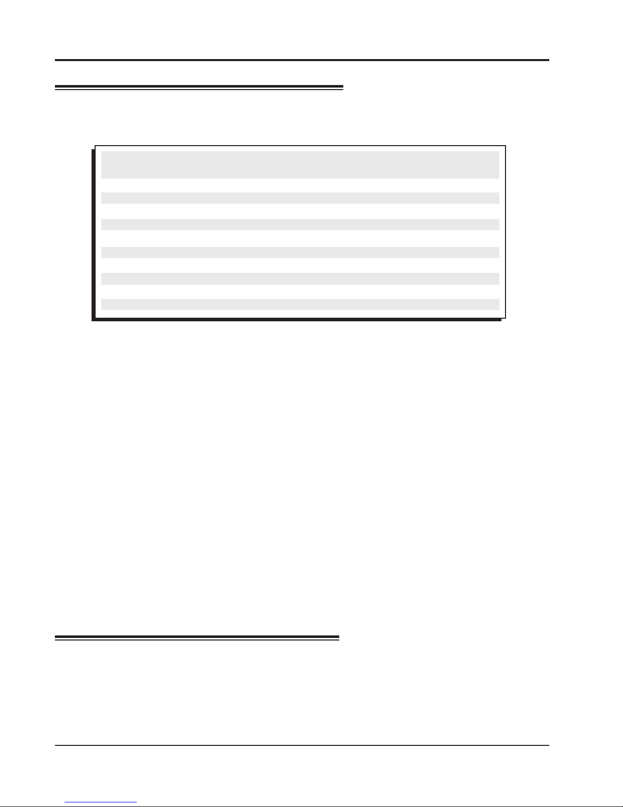
can cause a need for an ignition timing change. Figure 1 shows some of the factors that will affect
engine timing.
FACTOR Advance Timing Retard Timing
For For
Cylinder Pressure Low High
Vacuum High Low
Energy of Ignition Low High
Fuel Octane High Low
Mixture (Air/Fuel) Rich Lean
Temperature Cool Hot
Combustion Chamber Shape Open Compact
Spark Plug Location Offset Center
Combustion Turbulence Low High
Load Light Heavy
Figure 1 Ignition Timing Factors.
As you can see from the chart, most factors will change throughout the range of the engine operation.
The timing mechanism of the distributor must make timing changes based on these factors.
Example: An engine has 11:1 compression with a high energy ignition. With the specications given,
you will have to retard the timing for the high compression and high energy ignition. By comparing
the engine’s specications against the chart, a usable timing guideline can be found. Engines with a
combination of items from both columns will require a timing that is set in the mid range.
Obviously a full technical explanation of correct ignition timing would be very complicated. The best
way to arrive at a suitable ignition curve for your engine is to use the Ignition Timing Factors Chart
as a guide and compare it to the Advance Graphs in Figure 4 until a suitable curve is found. When
selecting your advance curve, use detonation (engine ping) as an indicator of too much advance, and
a decrease in power as an indicator of too little advance.
TIPS ON SELECTING AN ADVANCE CURVE
• Use as much initial advance as possible without encountering excessive starter load.
• Start the centrifugal advance just above the idle rpm.
• The starting point of the centrifugal advance curve is controlled by the installed length and
tension of the spring.
• How quickly the centrifugal advance (slope) comes in is controlled by the spring stiffness. The
stiffer the spring, the slower the advance curve.
• The amount of advance is controlled by the advance bushing. The bigger the bushing, the
smaller the amount of advance.
CENTRIFUGAL ADVANCE CURVE
SELECTING THE ADVANCE SPRINGS
The rate, or how quick the advance comes in is determined by the type of springs which are installed
on the distributor. The MSD distributors are equipped with two Heavy Silver springs installed. These
will give you the slowest advance curve possible (Figure 2). The parts kit contains two additional sets
of springs which can be used to match the advance curve to your particular application. Refer to the
Spring Combination Chart (Figure 3) for combinations that can be achieved.

INSTALLATION INSTRUCTIONS 3
MSD • WWW.MSDPERFORMANCE.COM • (915) 857-5200 • FAX (915) 857-3344
To change the springs, remove the cap and rotor and use needlenose pliers to remove the springs.
Be sure the new springs seat in the groove on the pin.
To change the springs, remove the cap and rotor and use needlenose pliers to remove the springs.
Be sure the new springs seat in the groove on the pin.
Figure 2 The Factory Equipped Curve.
Timing Curve From Factory
Figure 3 Spring Combination Chart.
SPRING COMBINATION RATE OF ADVANCE FIGURE 4
2- Heavy Silver SLOWEST A
1- Heavy Silver B
1- Light Blue
1-Heavy Silver C
1-Light Silver
2- Light Blue D
1- Light Silver E
1- Light Blue
2- Light Silver FASTEST F
Figure 4 Advance Curves.

4 INSTALLATION INSTRUCTIONS
MSD • WWW.MSDPERFORMANCE.COM • (915) 857-5200 • FAX (915) 857-3344
Figure 6 Changing the Advance Stop Bushing.
SELECTING THE ADVANCE STOP BUSH-
ING
Five different advance stop bushings are supplied
in the distributor kit. The distributor comes with a
Blue (21°) bushing already installed. If a different
amount of centrifugal advance is desired, follow the
next procedure to change the bushings. The chart
in Figure 5 gives the size and approximate degrees
for the corresponding bushings.
CHANGING THE ADVANCE STOP BUSH-
INGS
1. Remove the distributor cap and rotor.
2. Remove the locknut and washer on the bottom of
the advance assembly (Figure 6).
3. Remove the bushing and install the new one.
Install the washer and locknut. Do not overtighten.
LOCKING OUT THE CENTRIFUGAL
ADVANCE
1. Remove the advance components including the
springs, weights and the advance stop bushing
from the advance assembly.
2. Remove the roll-pin from the drive gear and
remove the gear from the shaft.
3. Slide the shaft two inches out of the housing.
4. Rotate the shaft 180° and insert the advance stop
bushing pin into the small hole on the advance
plate (Figure 7).
5. Install the locknut and washer to the advance stop
bushing pin. This locks the advance in place. Do
not overtighten.
6. Install the drive gear and roll-pin.
Figure 6 Locking Out the Centrifugal Advance.
Figure 7 Locking Out the Advance.
Figure 5 Advance Stop Bushing Chart.
BUSHING SIZE APPROXIMATE
CRANKSHAFT
DEGREES
Red-Smallest 28
Silver 25
Green 23
Blue 21
Purple 19
Black-Largest 18

INSTALLATION INSTRUCTIONS 5
MSD • WWW.MSDPERFORMANCE.COM • (915) 857-5200 • FAX (915) 857-3344
ADJUSTING THE SLIP COLLAR
Before installing the Pro-Billet Distributor, the slip collar adjustment must be set, follow this procedure.
1. Install the gasket to the housing then loosen the slip collar and insert the distributor into the engine
until it bottoms out against the oil pump drive.
2. After it bottoms out, raise the distributor 0.010" - 0.030" then slide the slip collar down into position
and tighten it.
CHECKING GEAR MESH
It is recommended to check for proper gear mesh between the cam gear and distributor gear. To
do this, coat the distributor gear with moly grease and install the distributor. Next, crank the engine
over several times. Before pulling the distributor out, make sure the rotor is in the position that lines
up with the original removal mark. Then pull the distributor out and inspect the gear pattern shown
on the grease. The proper mesh will leave an even pattern in the middle of the gear. Adjust the slip
collar to obtain the correct mesh.
Checking the Oil Pump to Distributor Shaft Overlap
The proper overlap between the distributor shaft and the oil pump intermediate shaft is very important.
The tongue of the distributor shaft should t into the groove of the oil pump shaft by at least 1/4".
To check this:
1. Measure the distance between the base of the slip collar to the tip of the distributor shaft (Figure 8).
2. Using a straight edge, measure the distance from the intake manifold distributor ange to the top
of the oil pump intermediate shaft (Figure 8).
3. Take the two measurements and subtract them. The difference is the overlap. If there is not enough
clearance or too much clearance, a different oil pump intermediate shaft is required.
Figure 8 Measuring Oil Pump Shaft Overlap.

6 INSTALLATION INSTRUCTIONS
MSD • WWW.MSDPERFORMANCE.COM • (915) 857-5200 • FAX (915) 857-3344
1. Remove the existing distributor cap without
disconnecting any of the spark plug wires.
2. With the cap off, crank the engine until the
rotor is aimed at a xed point on the engine or
rewall. Note this position by making a mark
(Figure 9).
3. Place the distributor cap back on and
note which plug wire the rotor is pointing
to. MARK THE SPARK PLUG WIRES and
remove the distributor cap.
4. Disconnect the wiring from the distributor.
5. Loosen the distributor hold down clamp
and slide the clamp out of the way.
6. Lift the distributor out of the engine.
Note that the rotor rotates as you lift
the distributor out. This is due to the
helical cut gear and should be taken into
consideration when installing the new
distributor.
7. Install the gasket and apply a liberal
amount of the supplied lubricant to the
distributor gear. (The supplied O-rings
can only be used if the block has been
modied as shown in Figure 10.)
8. Install the distributor making sure that the
rotor comes to rest pointing at the xed mark.
If the distributor will not fully seat with the
rotor pointing to the marked position, you
may need to rotate the oil pump shaft until the
rotor lines up and the distributor fully seats.
9. Position and tighten the hold down clamp
onto the distributor.
10. Install the distributor cap and spark plug wires
one at a time to ensure correct location. A
wire retainer is supplied to secure the wires
in place. Align the mounting bosses and use
the supplied 1.5" self-tapping Phillips screws
to hold the retainer in place (Figure 11).
Figure 9 Marking the Rotor Location.
INSTALLING THE DISTRIBUTOR
Figure 10 Modied Block for use with O-Rings.
Figure 11 Installing the Wire Retainer
NOTE: BLOCK MUST BE MODIFIED TO USE O-RINGS.

INSTALLATION INSTRUCTIONS 7
MSD • WWW.MSDPERFORMANCE.COM • (915) 857-5200 • FAX (915) 857-3344
Figure 12 Wiring to an MSD 6-Series Ignition Control.
Figure 13 Wiring to an MSD 7-Series Ignition Control.
GREEN
GREEN
PN 8860
HARNESS
VIOLET
VIOLET
ORANGE
BLACK
GRAY TACH OUTPUT
RED
WHITE
FROM IGNITION KEY
(ORIGINAL COIL WIRE)
MAGNETIC
PICKUP
DIGITAL 6AL
REV
LIMITER
(NOT USED)
WARNING: High voltage is present on the coil terminals. Do not touch the terminals or coil tower
when the engine is cranking or running.

Figure 14 Wiring with an MSD 7-Series Ignition and Timing Control.
Note: MSD 6 and 7 Series Ignitions
share the same color wiring.
Limited Warranty
M
SD warrants this product to be free from defects in material and workmanship under its intended normal use*,
when properly installed and purchased from an authorized MSD dealer, for a period of one year from the date of
the original purchase. This warranty is void for any products purchased through auction websites. If found to be
defective as mentioned above, it will be repaired or replaced at the option of MSD. Any item that is covered under
this warranty will be returned free of charge using Ground shipping methods.
This shall constitute the sole remedy of the purchaser and the sole liability of MSD. To the extent permitted by
law, the foregoing is exclusive and in lieu of all other warranties or representation whether expressed or implied,
including any implied warranty of merchantability or tness. In no event shall MSD or its suppliers be liable for special
or consequential damages.
*Intended normal use means that this item is being used as was originally intended and for the original application
as sold by MSD. Any modications to this item or if it is used on an application other than what MSD markets the
product, the warranty will be void. It is the sole responsibility of the customer to determine that this item will work
for the application they are intending. MSD will accept no liability for custom applications.
Service
In case of malfunction, this MSD component will be repaired free of charge according to the terms of the warranty.
When returning MSD components for warranty service, Proof of Purchase must be supplied for verication. After
the warranty period has expired, repair service is based on a minimum and maximum fee.
All returns must have a Return Material Authorization (RMA) number issued to them before
being returned. To obtain an RMA number please contact MSD Customer Service at 1 (888) MSD-7859 or visit
our website at www.msdperformance.com/rma to automatically obtain a number and shipping information.
When returning the unit for repair, leave all wires at the length in which you have them installed. Be sure to include
a detailed account of any problems experienced, and what components and accessories are installed on the vehicle.
The repaired unit will be returned as soon as possible using Ground shipping methods (ground shipping is covered
by warranty). For more information, call MSD at (915) 855-7123. MSD technicians are available from 7:00 a.m. to
5:00 p.m. Monday - Friday (mountain time).
MSD • WWW.MSDPERFORMANCE.COM • (915) 857-5200 • FAX (915) 857-3344
© 2016 MSD LLC
FRM 28913 Revised 08/16
This manual suits for next models
1
Table of contents
Other MSD Automobile Accessories manuals