MSD 7455 User manual

This Cap is designed to be used with MSD Pro Mags that are equipped with a Ford style cap (4"
terminal diameter) and rotor. If you have a Pro Mag 12 that has the small diameter distributor cap on
it, the unit must be sent to MSD to be modified to accept a Pro Cap.
Note: Blue Loctite or an equivalent thread locking compound is recommended for this installation.
ROTOR TIP INSTALLATION
Parts Included:
1 – Pro Cap, PN 7408
1 – Adapter Ring
1 – Rotor, PN 7423
1 – Rounded Rotor Tip
2 – O-Rings
2 – Plastic Hex Head Rotor Screws
4 – 8-32 x 1.25 Socket Head Cap Screws
4 – 10-32 x 1.25 Pan Phillips Screws
1 – Billet Housing
1 – Wire Retainer
4 – Self Tapping Screws
3 – Truss Head Phillips Screws
8 – Belleville Washers
3 – Stainless Washers
A modified Rotor Tip is supplied with the Pro Cap Kit, PN 7455, and the Pro Cap Rotor, PN 7423.
This Rotor Tip must be used when the ignition timing of the Pro Mag is being retarded. The modified
Rotor Tip has a 90° corner on one side and a rounded edge on the opposite side. Installation of the
Tip depends on the rotation of the Pro Mag. The rounded edge of the rotor must point in the direction
of the mag's rotation (the rounded edge is always the leading side). Note that there is also an arrow
designating the rotation stamped on both sides of the new Tip.
The reason for this modification is because voltage will travel to and from the sharpest point of the rotor tip.
By rounding the leading edge of the Tip, the voltage will jump from the sharp point (trailing edge) of the tip
which will be closer to the spark plug wire terminal when the timing is retarded. This will produce proper
spark distribution even when the timing is retarded (which alters the rotor phasing).
The Figures show the Rotor Tip installation.
CCW
ROTATION
CCW
ROTATION
CW
ROTATION
CW
ROTATION
Figure 1 Installing the Rotor Tip.
Pro Cap for the MSD Pro Mag
PN 7455
ONLINE PRODUCT REGISTRATION: Register your MSD product online. Registering your product
will help if there is ever a warranty issue with your product and helps the MSD R&D team create
new products that you ask for! Go to www.msdperformance.com/registration.
MSD • www.msdPERFORmANCE.COm • (915) 855-7123 • FAX (915) 857-3344

2 INSTALLATION INSTRUCTIONS
MSD • www.msdPERFORmANCE.COm • (915) 855-7123 • FAX (915) 857-3344
Figure 2 Removing the Original Cap, Rotor and Drive. Figure 3 Removing the Cover and Billet Housing.
Remove
Remove
INSTALLATION
1. Remove the existing distributor cap, rotor, rotor drive and spacer ring (Figure 2).
2. Remove the four Allen bolts and pull the upper
billet aluminum housing off the generator
(Figure 3).
3. Install the new billet base with the existing four
screws with a small amount of Blue Loctite on
the threads (Figure 4).Tighten the screws in a
criss-cross pattern.
4. Install the new adapter ring to the generator
using the three new Truss head Phillips screws
and flat washers. Position the adapter ring so
the screws are in the middle of the adjustment
slots (Figure 5). This gets the rotor phasing
close enough to fire the engine to properly set
the phasing.
Note: It is recommended to check the rotor phasing
after the installation.
5. Apply Loctite to the threads of the rotor drive
screw. Make sure the belleville washer is in place
and install the rotor drive.
Figure 4 Installing the New Billet Housing.
Figure 5 Installing the Adapter Ring.
Center the
Screws in
the Slots.
Center the
Screws in
the Slots.

INSTALLATION INSTRUCTIONS 3
MSD • www.msdPERFORmANCE.COm • (915) 855-7123 • FAX (915) 857-3344
Figure 7 Installing the Wire Retainer.
Figure 6 Installing the Rotor.
O-Ring
Belleville
Washer
6. Install the rotor making sure that it is placed correctly on the mount and the alignment dowels are
seated before installing the rotor hold down screws. Install one O-ring on each of the over-molded
rotor screws for increased spark isolation as well as a belleville washer (Figure 6). Torque screws
to 30-32 in-lbs.
7. Install the distributor cap
with the four Phillips
screws and belleville
washers. Connect the
spark plug wires to their
corresponding posts.
8. Install the wire retainer
over the wires and secure
it with the supplied self
tapping screws (Figure
7). Depending on the style
spark plug boots used,
the retainer may not sit
flush on the posts of the
cap.

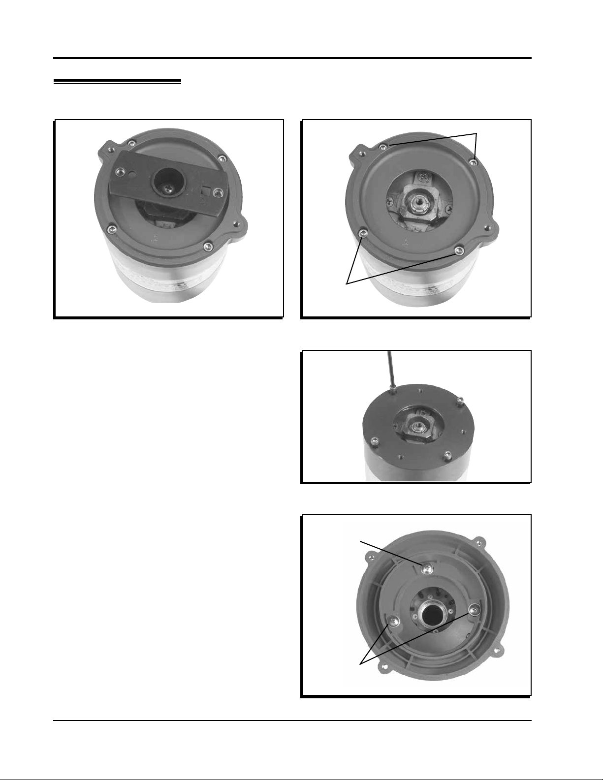
DISTRIBUTOR CAP MAINTENANCE
Like any part of your vehicle, the cap and rotor should be inspected periodically for signs of wear or
carbon tracking.
• Inspect the condition of the rotor tip. The rotor tip should be secure and appear in good shape. Over
time the tip will show obvious signs of wear and deterioration. The center of the rotor tip should
not be burned or appear pitted.
• Check for signs of Carbon Tracking. Carbon tracking can be caused by a crack in the cap or rotor
and could cause a misfire, usually under load when the most voltage is needed to jump the gap
of the spark plug. Carbon tracking appears as small traces that are left when the spark jumps to a
different (easier) path to ground.
• Moisture can affect the transfer of the spark voltage and energy. Make sure the inside of the cap
is clean and dry. Ionization, the build up of conductive gases (ozone) inside the cap, acts as a
conductor and can cause spark scatter.
• In some high humidity areas, it may be necessary to vent the cap to prevent moisture and eventual
buildup of corrosion and ozone gases inside the cap. To vent the cap, drill three or four ¼” holes
in the spacers below the rotor.
• Replacement Parts: Cap, PN 7408
Rotor, PN 7423
Base, PN 7456
Limited Warranty
MSD warrants this product to be free from defects in material and workmanship under its intended normal use*,
when properly installed and purchased from an authorized MSD dealer, for a period of one year from the date of
the original purchase. This warranty is void for any products purchased through auction websites. If found to be
defective as mentioned above, it will be repaired or replaced at the option of MSD. Any item that is covered under
this warranty will be returned free of charge using Ground shipping methods.
This shall constitute the sole remedy of the purchaser and the sole liability of MSD. To the extent permitted by
law, the foregoing is exclusive and in lieu of all other warranties or representation whether expressed or implied,
including any implied warranty of merchantability or fitness. In no event shall MSD or its suppliers be liable for special
or consequential damages.
*Intended normal use means that this item is being used as was originally intended and for the original application
as sold by MSD. Any modifications to this item or if it is used on an application other than what MSD markets the
product, the warranty will be void. It is the sole responsibility of the customer to determine that this item will work for
the application they are intending. MSD will accept no liability for custom applications.
Service
In case of malfunction, this MSD component will be repaired free of charge according to the terms of the warranty.
When returning MSD components for warranty service, Proof of Purchase must be supplied for verification. After
the warranty period has expired, repair service is based on a minimum and maximum fee.
All returns must have a Return Material Authorization (RMA) number issued to them before
being returned. To obtain an RMA number please contact MSD Customer Service at 1 (888) MSD-7859 or visit
our website at www.msdperformance.com/rma to automatically obtain a number and shipping information.
When returning the unit for repair, leave all wires at the length in which you have them installed. Be sure to include
a detailed account of any problems experienced, and what components and accessories are installed on the vehicle.
The repaired unit will be returned as soon as possible using Ground shipping methods (ground shipping is covered
by warranty). For more information, call MSD at (915) 855-7123. MSD technicians are available from 7:00 a.m. to
5:00 p.m. Monday - Friday (mountain time).
MSD • www.msdPERFORmANCE.COm • (915) 857-5200 • FAX (915) 857-3344
© 2014 MSD LLC
FRM28746 Revised 09/14 Printed in U.S.A.
Other MSD Industrial Equipment manuals