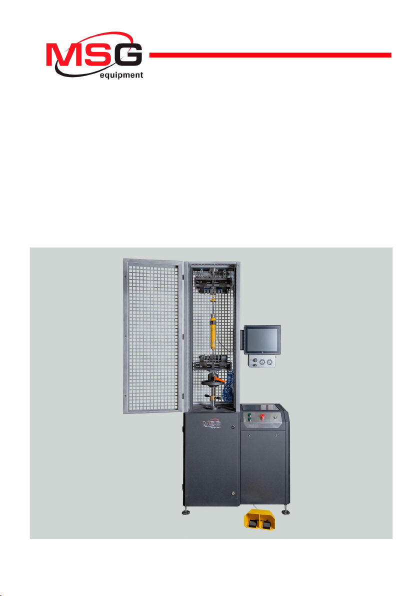
MSG Equipment MS1000+ User manual

2022.09.15
MS1000+
MANUAL FOR DIAGNOSING
SHOCK ABSORBERS
INSTRUKCJA DIAGNOSTYKI
AMORTYZATORÓW
ИНСТРУКЦИЯ ПО ДИАГНОСТИКЕ
АМОРТИЗАТОРОВ
UNIQUENESS
TRAINING
SERVICE
INNOVATION
WARRANTY
QUALITY


English
Operation manual
3
CONTENTS
INTRODUCTION....................................................................................................................................................4
1. TEST BENCH DESCRIPTION............................................................................................................................5
2. TEST BENCH MENU..........................................................................................................................................9
3. APPROPRIATE USE........................................................................................................................................12
3.1. Safety regulations..............................................................................................................................12
4. SHOCK ABSORBER DIAGNOSIS..................................................................................................................13
4.1. Preparing the test bench and shock absorber for mounting.................................................13
4.2. Mounting the shock absorber on the test bench......................................................................15
4.3. Shock absorber diagnostics in automatic mode...................................................................... 20
4.3.1. Recording a working diagram......................................................................................................22
4.3.2. Recording shock absorber characteristics...............................................................................23
4.4. Assessment of test results ..............................................................................................................23
4.5. Shock absorber manual test.......................................................................................................... 24
5. CHANGING SHOCK ABSORBER WORKING STROKE................................................................................25
CONTACTS.......................................................................................................................................................... 26

English
Test bench MS1000+
4
INTRODUCTION
This manual describes how to obtain data on the technical condition of the shock absorber on
the MS1000+ test bench (hereinafter, “the bench”).
WARNING! The manufacturer is not responsible for any damage or harm to human health
resulting from non-compliance with the requirements of this manual.
The bench is designed to record the operating diagram of the shock absorber (resistance force
dependence on the position of the piston) and its working characteristics (shock absorber
resistance dependence on the speed of movement of the piston) by which it is possible to
determine:
• need to repair/replace the shock absorber;
• cause of the fault;
• quality of the repaired shock absorber;
• compliance with the performance characteristics of shock absorbers to technical
requirements.
Also, the bench allows for long-term tests of the shock absorber.
WARNING! It is forbidden to check the shock absorbers with the spring, because this can lead
to the breakdown of the bench.
The bench has the following possibilities:
• Diagnostics of all types of shock absorbers of vehicles with different types of fastenings and
resistance force up to 1000 kg.
• Diagnostics of electronically controlled shock absorbers with MS203 adapter.
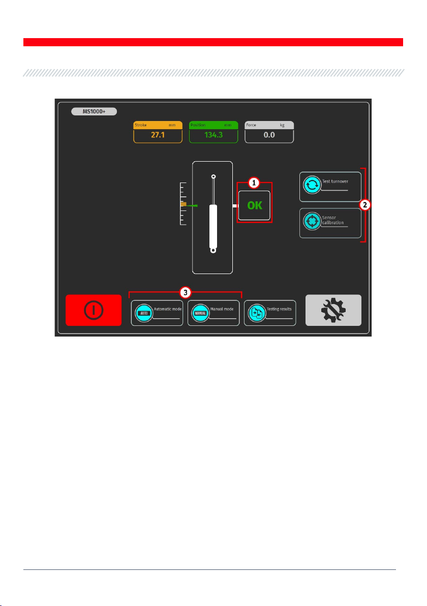
• The diagnostics of the shock absorbers on the bench can be carried out in automatic and
manual modes:
- automatic mode is designed to remove the working diagram and the operating characteristics
of the shock absorber;
- manual mode is designed for shock absorber pumping before diagnostics, shock absorber
analysis at a certain (desired) frequency and required time period, testing of electronically
controlled shock absorbers with MS203 adapter.
• Keeping the results obtained in automatic diagnostic mode and printing them.
• Comparison of diagnostic results with reference data, for example, comparison of test results
of new original shock absorber with diagnostic one.

English
Operation manual
5
1. TEST BENCH DESCRIPTION
The bench consists of the following main parts (fig. 1):
Figure 1. Main elements of the bench
1 - mechanical compartment;
2 - the test zone and contains a diagnostic shock absorber;

English
Test bench MS1000+
6
3 - touch display provides diagnostic data output and control of bench functions;
4 - block filling shock absorbers with nitrogen;
5 - control panel, provides power control of the bench and control of pneumatic clamps;
6 - electrical compartment;
7 - pneumatic clamp control pedal unit, duplicates the buttons on the control panel.
Work with the diagnosed shock absorber is carried out in the test area (Fig. 2), which includes:
Figure 2. Test area of the bench
1- pneumatic upper clamp;
2- temperature sensor and zip tie for its attachment to the shock absorber;
3- pneumatic lower clamp;
4- stopper of the lower clamp;
5- wheels for adjusting of height lower clamp;
6- stopper for adjustment of lower clamp height.

English
Operation manual
7
The following elements are arranged on the control board (Fig. 3):
Figure 3. Control board
1- buttons for controlling pneumatic clamps;
2- button «EMERGENCY STOP»- emergency power off of the bench;
3– button «OFF/ON»- power off/on of the bench. If the «EMERGENCY STOP»button is pressed,
the «OFF/ON»button has no effect.
The shock absorber is fixed in the test area by pneumatic clamps, which have the following basic
elements, see Figures 6 and 7.
Figure 4. Elements of the top pneumatic clamp:
1 - cam; 2 - slider guide; 3 - slider; 4 - locking nut; 5 - pusher.

English
Test bench MS1000+
8
The lower pneumatic clamp (Fig. 7) has interchangeable fixtures (Fig. 2) which allow for the fixation
of shock absorbers with different types of anchorages.
Figure 5. Elements of the lower pneumatic clamp:
1 - cam; 2 - slider guide; 3 - slider; 4 - locking nut; 5 - pusher;
6 - installation screw; 7 - device for fixing the shock absorber.

English
Operation manual
9
2. TEST BENCH MENU
The initial menu of the bench (Fig. 6) is activated when the door of the test area of the bench is
opened and contains:
Figure 6. The initial menu of the bench
1- Pneumatic clamp control buttons.
2- Information field that displays the current values of the stroke of the piston, the force on the
rod.
3- Button to switch to the bench setup menu.
4- Button to switch to «Comparison of results» the menu.
5- Button «Turn off the bench». This button turns off the computer of the bench, complete
bench disconnection is carried out by the button «ON/OFF» on the control panel (pos.3 fig.3).

English
Test bench MS1000+
10
The main menu of the bench (fig. 7) contains:
Figure 7. Stand main menu
1- Information field in which the status of the bench readiness for diagnosis is displayed. The
following values can be displayed:
«OK» - stand is ready for diagnostics;
«Failed» - sensor calibration error;
«Low pressure» - low pressure in pneumatic system.
2- Buttons to prepare the bench for diagnosis:
«Test turnover» - when pressed, the benchwill perform one operating cycle of the shock
absorber and will calibrate the position sensor. After the test turnover is completed,
diagnostics will be available.
«Strain gauge calibration» - when pressed, the bench will calibrate the force sensor.
3- Select the diagnostic mode. The buttons become active after the test turn and successful
calibration of the sensors.

English
Operation manual
11
The bench configuration menu (fig. 8) contains:
Figure 8. The bench configuration menu
1- Shock absorber temperature thresholds:
«Tmax» - the maximum temperature value, after which the diagnostic process will be
stopped;
«Tmin» - the value of the temperature below which the diagnostics of the shock absorber
after exceeding the temperature «Tmax» will be available.
2- On/off reading of temperature sensor.
3- Company logo selection field on the results report.
4- Field for specifying the name of the company and the employee who performed the
diagnostics in the results report.
5- Interface language selection field.
6- Strain gauge settings. These settings can only be changed in consultation with MSG equipment
Support.
7- Button of exit to the bench operating system.
8- Field for setting units of measurements: force, temperature and displacement.

English
Test bench MS1000+
12
3. APPROPRIATE USE
1. The bench is used only for its intended purpose (see sect. INTRODUCTION).
2. In the test area, it is prohibited to carry out any repair work on the shock absorber. This may
lead to the breakdown of the bench.
3. The shock absorber mounts securely in the pneumatic clamp. Do not allow any backlash
between the shock absorber and pneumatic clamps. This will result in unreliable diagnostic data
and a breakdown of the bench.
4. It is prohibited to test a knowingly defective shock absorber and shock absorber with a spring.
5. The bench shutdown should be performed through the interface of the service program, by
clicking on the «Turn off the bench». After the monitor goes out, you can turn the «ON/OFF»
button into the «OFF» position.
6. Use the button «EMERGENCY STOP» only if necessary to stop the diagnostic process in an
emergency.
7. The touch screen saving uses the stylus (supplied as a set).
8. The bench operating is prohibited in a defective condition and not connected to the ground.
9. To avoid damage or failure of the bench, it is not allowed to make changes to the bench at
one's discretion. The bench cannot change by anyone other than the official manufacturer.
10. Computer equipment and software use not designed to work with this bench voids warranty
obligations (even if the software and equipment were subsequently deleted). Only the original
MSG equipment software can be installed on this hardware.
11. In the case of a breakdown in the operation of the bench, it should be stopped further and
contact the manufacturer or the sales representative.
3.1. Safety regulations
1. Specially trained persons who have been given the right to work at the bench of certain types
and who have been instructed on safe techniques and working methods are allowed to work with
the bench.
2. Electrical supply of the bench is prohibited to turn on with the open doors of the mechanical
and/or electrical compartments. It is also PROHIBITED to open the door of the electrical
compartment until 10 minutes after the power is cut.
3. Shock absorber on the bench mounting and then dismantling is extra careful to prevent the
unit from falling.
4. The workplace shall always be clean, well-lit, and have enough free place.
5. The bench disconnects from the electrical network before starting any maintenance work.
6. To ensure electrical and fire safe PROHIBITED:
- connect the bench to the electrical network having faulty protection against current
overloads or not having such protection;
- to use a socket without a grounding contact to connect the bench;

English
Operation manual
13
- use extension cords to connect the bench to the electrical network. If the socket is
removed from the site of installation of the bench, it is necessary to make adjustments to
the electrical network and install the socket;
- operation of the bench in defective condition.
- independently to repair and make changes to the design of the bench, because it can lead
to serious damage to the bench and deprive the right to warranty repair.
5. It is forbidden to leave unattended units on the bench with the drive running.
4. SHOCK ABSORBER DIAGNOSIS
4.1. Preparing the test bench and shock absorber for
mounting
Install one of the equipment sets (Fig. 9) corresponding to the type of mounting of the shock
absorber in the lower pneumatic clamp, see Fig. 11. If the top mounting of the shock absorber
has a threaded part, twist the prism on it (Fig. 10).
Figure 9. Interchangeable fasteners for lower pneumatic clamp for various types of shock
absorber anchorages
Figure 10. Prisms for fixing shock absorbers
1- prisms for fixing shock absorbers with shaft threaded tip (identical);

English
Test bench MS1000+
14
2- prism with uncalibred holes (for non-standard shock absorber shafts). Prism is a workpiece
for manufacturing a special shock absorber attachment by cutting the necessary thread.
Figure 11. Types of shock absorber mounts and a combination of devices
for mounting them on the bench

English
Operation manual
15
To replace the shock absorber fixation device in the lower pneumatic clamp, it is necessary to
unscrew the mounting screw pos.6 fig. 5 and pull out the device. Next, set the device to stop and
spin the installation screw.
Figure 12. Replacement of the shock absorber fixation in the lower pneumatic clamp.
4.2. Mounting the shock absorber on the test bench
The shock absorber shall be mounted on the bench in the following sequence:
1. Turn on the bench.
2. Pull the shaft out of the shock absorber to the maximum value.
3. Place and fix the shock absorber in the upper clamp with the shaft up, for this:
3.1 Position the top mounting of the shock absorber (prism) coaxially with the pneumatic clamp
pushers (see fig. 15) and «Clamp» it.
3.2. Alternately rotating pushers (see pos.5 of Figure.4) position the shock absorber so that its
shaft is located in the middle of the pneumatic clamp (Fig. 16). It is necessary to control the correct
positioning of the cams (see pos. 1. fig. 4), they must be fully extended (see fig. 17).

English
Test bench MS1000+
16
Figure 13. Correct position of pneumatic clamp pushers relative to shock absorber attachment
before «clamping»
Figure 14. Shock absorber positioning in clamp

English
Operation manual
17
a b
Figure 17. Position of the pneumatic clip cams in the «clamp» state
a - not right; b - right.
3.3. Additionally, tighten the pushers to the shock absorber mount (prism), and then tighten the
lock nuts pos.4 fig.4 (see fig.18).
Figure 18. Tightening of the locking nuts in the clamp
4. Install and fix the shock absorber in the lower clamp, for this:
4.1. Loosen the stopper of the lower clamp by turning the lever pos.4 fig. 2 counterclockwise by 2
turns (see fig. 19).

English
Test bench MS1000+
18
Figure 19. Loosening the bottom clamp stopper
4.2. Loosen the stopper for adjusting the height of the lower clamp pos.6 fig. 2 by turning the
lever counterclockwise (see fig. 20).
Figure 20. Loosening the lower clamp height adjustment stopper

English
Operation manual
19
4.3. While holding the pneumatic clamp from turning, use the lower pneumatic clamp height
adjustment wheel to set the pneumatic clamp pushers coaxially with the lower shock absorber
mount (prism) (see Fig. 21).
Figure 21. Adjusting the height of the lower pneumatic clamp
4.4. «Clamp» the pneumatic clamp and position the shock absorber along the middle of the
pneumatic clamp in the same way as with the upper clamp, see pos. 3.2.
4.5. In addition, tighten the pushers to the shock absorber mount (prism), and then tighten the
lock nuts.
4.6. By turning the height adjustment wheel of the lower pneumatic clamp counterclockwise, set
the working height of the shock absorber. Usually it is 3 - 5 turns, but at least 2 turns.
4.7. Fix the height adjustment stopper and the lower clamp stopper.
5. Place and clamp the temperature sensor on the shock absorber (Fig. 22).
6. Close the test chamber door.

English
Test bench MS1000+
20
Figure 22. Installed temperature sensor
4.3. SHOCK ABSORBER DIAGNOSTICS
IN AUTOMATIC MODE
To activate the diagnostic modes it is necessary to press the button «Test turnover», then
«Calibration of the strain gauge» on the screen of the main menu see. pos. 2 fig. 8. After that,
diagnostic modes become active.
WARNING! At the test speed, the operator’s hand should be on the emergency the bench
disconnection button so that in the event of an emergency, the engine on the bench will stop
instantly.
To switch to the automatic mode of operation of the stand it is necessary to press the button
«Automatic mode».
Other manuals for MS1000+
2
Table of contents
Languages:
Popular Industrial Equipment manuals by other brands

RIEGLER
RIEGLER G Series quick start guide

Bosch
Bosch EL-53000 Parts list and operating instructions

Pottinger
Pottinger CAT 310 plus front Excerpt from operating manual

ABB
ABB XAC25291 Operation manual

KTR-Group
KTR-Group ROTEX GS Operating & assembly instructions

Orwak
Orwak 3120 Original operating instructions