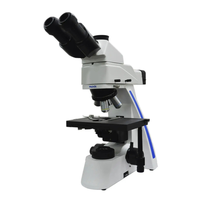
MshOt MF43-N User manual

Guangzhou Micro-shot Technology Co., Ltd
MF43-N
Research grade fluorescence microscope
User Manual
Website:www.m-shot.com
Tel:0086-20-38262481
Email: sales@mshot.com

Research grade fluorescence microscope MF43-N

Thank you for buying our product!
This unit is a precision optical instrument. Though with high safety design, wrong usage and overlook of this manual
can do harm to you and your property. Thus, to ensure the life of this unit and maintain it properly, please read this
manual carefully before operating.
Safety Reminder
1. Be sure to turn off the power switch and remove the power cord before installing, replacing the
bulb or fuse, plugging and unplugging the power supply.
To prevent electric shock or fire, be sure to turn off the power switch and remove the power cord
before installing this unit, replacing the bulb or fuse, plugging and unplugging the power supply.
2. Do not disassemble
Except the removable parts mentioned herein, no part of this unit shall be removed, otherwise the
performance of this unit may be reduced, or may cause an electric shock, injury or damage to this
unit. Please contact the supplier if any fault occurs.
3. Input voltage
Check if the input voltage is consistent with your local voltage supply. If not, do not operate this
unit and contact the supplier. Improper input voltage may cause a short circuit or fire thereby
causes damage to this unit.
4. Use specific bulb, fuse and power cord
Use of an improper bulb, fuse or power cord may cause damage or fire to this unit. Any extended
power cord used must be grounded (PE).
5. Protect this unit from high temperatures, dampness and foreign objects
To prevent short circuit or any other fault, do not expose this unit to any high temperatures or
dampness environment for a prolonged period of time. A suitable operating environment is
designated at a temperature of 5°C-35°C, and relative humidity of 20%-80% (at 25°C). If water splashes on this unit,
turn off the power switch and remove the power cord immediately, and then wipe the water off with dry cloth. When any
foreign object enters or drips onto this unit, please stop operating the unit and contact the supplier.
6. Heat of light source
The lighting bulb generates high temperatures during operation. Do not touch the collector lens or
lamp box when the lamp is illuminated, and do not touch the bulb within 30 minutes after the
lamp goes out due to high temperatures arising from operation. When replacing the bulb, make sure it has cooled down
properly (the lamp should be off for at least 30min).
★To prevent burn, do not touch the bulb when the lamp is illuminated or within 30min after it goes out.
★To prevent fire, do not place any fibrous product, paper, flammable or explosive material (e.g., gasoline,
petroleum ether, alcohol) near the halogen lamp housing or mercury lamp housing.
!
Warning!
!
Warning!
!
Warning!
!
Warning!
!
Warning!
!
Warning!

www.m-shot.com
7. Coarse/fine focusing knobs
This unit employs a coarse/fine coaxial focusing mechanism. Do not turn the left/right coarse/fine
focusing knob in the opposite direction. When the objectives lifting device reaches the limit of
motion, do not continue to turn the coarse focusing knob, otherwise the focusing mechanism may be damaged.
8. Storage place
This unit is a precision optical instrument, and improper operation or storage may cause damage or
its precision may be adversely affected. Consider the following when selecting a storage place:
※Avoid placing the unit under direct sunlight, directly under interior lighting or any other bright place.
※A suitable operating environment is designated at a temperature of 5°C-35°C, and relative humidity of 20%-80% (at
25°C). Do not expose this unit to high temperatures, dampness or dust for a prolonged period of time, otherwise mist or
mold may develop or dust may deposit on the lens, thus cause damage to this unit and shortening its life.
9. Installation of bulb
Do not touch the glass surface of the bulb directly with bare hands. When mounting the bulb, wear
gloves or wrap it with cotton material.
※Wipe off any dirt on the surface of the bulb with a clean cotton fabric dipped in alcohol. If the dirt is not
thoroughly removed, it would etch the surface of the bulb weakening its brightness and shortening its life.
※Mount the bulb with care to avoid slipping off or injuries to your fingers.
※When replacing the bulb, make sure its contact is intact. If its contact is damaged, the bulb may be disabled or
short-circuited.
※When replacing the bulb, the feet should be inserted into the holder as deeply as possible. If the feet are not
tightly inserted, the bulb may go out or short circuit.
10. Instrument handling
This precision optical instrument is heavy and should be handled with care. Strong impact and
rough handling are strictly prohibited, it may cause damage to this unit.
11. Environmental protection
Please dispose the wastes from the packaging and operation of this unit by category such as
cartoon, foam, plastic, bulb and etc. Do not discard the damaged mercury lamp carelessly in order
to avoid creating environmental poll
!
Warning!
Caution!
Caution!
Caution!

Content
Ⅰ. Components..................................................................................................................... 1
Ⅱ. Installation and operation.............................................................................................. 2
1. Baisc operation...........................................................................................................................................................3
2. Microscope operation................................................................................................................................................ 4
3. Adjust alignment........................................................................................................................................................5
4. Adjustable aperture diaphragm............................................................................................................................... 6
5. Focusing system......................................................................................................................................................... 7
6. Stage............................................................................................................................................................................ 8
7. Adjust the tension of the x-axis and y-axis knobs...................................................................................................8
8.Adjust the alignment of fluorescent light path.....................................................................................................11
Ⅲ. Installations steps...........................................................................................................9
1. Install LED lamp house.............................................................................................................................................9
2. Install objective nosepiece.......................................................................................................................................10
3. Install cable.............................................................................................................................................................10
4. Install condenser...................................................................................................................................................... 11
5. Install stage..............................................................................................................................................................11
6.Install gripper...........................................................................................................................................................11
7. Install fluorescence attachment..............................................................................................................................12
8. Install fluorescence light box.................................................................................................................................12
9.Fluorescent module installation cable...................................................................................................................12
10.Install eyepiece tube................................................................................................................................................13
11. Installing eyepiece...................................................................................................................................................13
12.Install adapter..........................................................................................................................................................13
13.Install the power cord.............................................................................................................................................14
Ⅳ、Broad spectrum LED light source..........................................................................15
Ⅴ、Troubleshooting guide................................................................................................ 17
Ⅵ、Technical specification................................................................................................ 23

1
Field diaphragm
Eyepiece
Trinocular tube
Fluorescence filter wheel
Host
Fluorescence illuminator lamp house
Fluorescence light barrier plate
X/Y stage hand wheel
Ⅰ.Components

2
Camera adapter(need to buy separately)
Focusing wheel
Light intensity rotate knob
Fluorescence illuminator
Objective
Stage
Bright field illuminator
power button

3
Ⅱ.Installation and operation
2-1、Basic operation
1. Turn on the power supply: turn on the power
supply and turn the main switch on the side of the
microscope to the "-" state.
2. Adjust the light intensity: turn the knob to
adjust the lighting intensity.
SET LIM(light intensity control)brightness
1、Turn off LIM switch ① (when LIM
indicator light ② is off) and turn the low
magnification objective into the light path to
focus the sample.
2、Turn the brightness adjustment knob ③
to select the best observation brightness. Press
the LIM setting button (set key) to input the
current brightness.
3、Repeat the above steps to set the best
brightness for each objective.
Each objective can be set a special brightness separately. After setting the brightness
for the objective lens, when the objective lens is selected, turn on LIM switch ①, and
the brightness will be automatically adjusted to the preset value; If it is necessary

4
to reset the best brightness, turn off LIM switch
① (when LIM indicator light ② goes out), turn
the objective lens that needs to reset the best
brightness into the optical path, turn off Lim
switch, and then repeat the above steps 3 and
4.Rotating the focusing knob to lower the stage.
3. Pull the slide holder apart and place the slide.
4. Rotate the objective holder to turn the 10x objective into the optical path(Adjust the
fluorescent accessory to neutral)
5. Rotate the coarse and fine focus system to focus the sample.
6. Moving the stage control hand wheel to adjust the observation sample area
2-2 Microscope adjustment
1. Adjust the pupil distance: adjust the binocular
lens tube to the left and right till the right field of
view is completely coincident.
Adjust the diopter: turn the diopter adjusting rings
on both sides to the scale "0", turn the 40x
objective into the optical path, observe with the
right eye from the right eye lens, and focus the
sample by rotating the coarse and fine focus
spiral.Turn the 10x objective into the optical path, and turn the right diopter adjusting ring

5
①to focus the sample. Do not adjust the coarse and fine focusing knob during focusing
system. Use the left eye to observe from the left lens, turn the left diopter adjusting ring
②to focus the sample.
Use eyepiece rubber clap
When wearing glasses, put the goggles in the normal
folded position to prevent eye contact and scratching.
When not wearing glasses, open the folded eyepiece
rubber clap in the direction of the arrow to prevent the
external light between the eyepiece and the eye from
entering.
2-3 Adjust alignment
1. Put on the sample.
2. Rotate the objective nosepiece and select 10x objective.
3. Turn the coarse and fine focusing knob to focus the sample.

6
物镜视场外缘
数值孔径刻度
孔径光阑图像
4. Turn the height of the condenser and adjust the knob of the condenser to raise the
condenser to the highest level.
5. Rotate the field of view diaphragm adjusting ring along the direction of the arrow to
reduce the diaphragm.
6. Turn the coarse and fine focusing knob to focus the field aperture image.
7. Turn the two centering screws of the condenser to move the field aperture image to the
center of the field of view.
8. Rotate the adjustment ring of the field of view diaphragm to make the field of view
diaphragm connected to the field of view.
Note: do not screw the fixing screw of the condenser in the middle of the alignment knob
wrong
2-4 Adjustable aperture diaphragm
1. Rotate the adjusting ring of the numerical aperture of the condenser to make the
numerical aperture of the condenser equal to 70% - 80% of the numerical aperture of the
objective. According to the image, the aperture size can be adjusted to the position of
moderate image resolution and contrast.

7
2. Remove the eyepiece and observe from the lens barrel. The aperture image can be seen,
as shown in Figure 2 above.
2-5Focusing system
1Coarse focus knob: move the stage up and
down to focus
2Fine focus knob (right side of frame): fine
adjustment of focusing position
3Fine focus knob (left side of bracket) to fine adjust the focus position
4Coarse focus limiting device: set the upper limit of stage position (to avoid collision)
After locking the coarse focus limit device, the coarse adjustment travel
will be limited to the position set by the limit and cannot rise to the height
beyond the limit.
5Loose and tight device for coarse and accurate focus: adjust coarse and accurate focus,
rotate focus, rotate focus
6The tightness of the knob as it turns. The coarse focusing device has been adjusted in
advance and is easy to use.
If necessary, the loose and tight state can be changed by using the loose
and tight device ⑤. When the adjusting ring is rotated in the direction of
the arrow, the helical tension of the coarse focus increases, on the contrary,
it decreases.

8
2-6 Stage
①Turn the coarse focusing knob to lower the
stage.
②Open the spring finger ②on the slide holder,
slide one or two sample slides from the front into
the stage.
③Push the slide in as far as you can, and then gently release the trigger
The slide size should be 26 × 76mm, 0.9 to 1.2mm in thickness, and 0.17mm in thickness.
When observing a large sample, remove the clip and put the sample directly on the stage.
2-7 Adjust the tension of the x-axis and y-axis knobs
Hold the x-axis knob ①, screw the y-axis knob ②
upward to expose the knob rod.
1、Turn the x-axis adjusting knob ③or y-axis adjusting
knob ④clockwise (arrow direction) to increase the
tension, and turn the y-axis adjusting knob ④
counterclockwise to decrease the tension.
If the tension is adjusted too tightly, the
clucking sound can be heard when the stage rises
or falls, or the accuracy of the stage stop is reduced.
Rotating stage
1、Slightly loosen the table fixing knob ①.
2、Using the fixed knob of the loading platform,
the platform can rotate clockwise or
anticlockwise.
It is normal to hear and feel a click
during rotation

9
Adjust the height of the stage
1、Lower the stage to the lowest level, and then remove the stage from the microscope.
2、Using a hexagon screw driver, loosen the fixed screw ① of the stage bracket to remove
the stage bracket.
3、Turn the coarse focus knob to raise the focus
slide plate ③ to the place where the limit screw
can be seen from the mirror arm
4、Use a hexagon screw driver to loosen and remove
the upper limit screw ②.
Re-install the stage bracket and stage
Please keep the removed screws properly
for reuse.
Use oil mirror
1、Focus the sample in the order from low
magnification objective to high magnification
objective
2、Before using the oil lens, place a drop of oil
on the area to be observed of the sample.
3、Turn the objective nosepiece into the optical
path and adjust the fine focus button.
Bubbles in the oil will affect the observation,
please make sure there are no bubbles in the oil
Ⅲ、Installation steps
3-1 Install LED light room
1、1. Align the fixing screw ②with the screw
hole ②, and install the LED lamp chamber ①
into the mounting hole at the back of the
microscope.

10
2、Use the hexagon key to tighten the set screw
②.
3、Insert the plug ④on the lamp chamber into the
socket of microscope ⑤.
3-2Install the objective nosepiece
1、Turn the coarse focusing knob to lower the
stage.
2、Slightly loosen the fixing screw ①of the
objective turntable.
3、Do not screw the fixing screw ①too loose,
otherwise it is difficult to replace the objective nosepiece.
3、Hold the objective lens nosepiece, keep the dovetail mounting port ②horizontal,
insert it into the dovetail ③on the microscope arm, and gently push it into the end.
4、Tighten the fixing screw of objective lens turntable ①.
When installing or removing the objective nosepiece with cable, the cable
must be removed in advance.
3-3 Installing cables
Pass the cable ④under the microscope body
arm to the rear panel, let the cable pass through
the cable rack, and then plug the cable into the
socket on the rear panel.

11
①
②
3-4 Install the condenser
1、Turn the coarse focusing knob ①to raise the
stage to the highest position.
2、Turn the condenser height adjusting knob ②
to minimize the condenser frame.
3、Completely loosen the fixing screw ③
of the condenser.
4、Hold the condenser with the numerical aperture number facing forward. Carefully push
the condenser into the innermost part along the dovetail slot.
5、Tighten the fixing screw ③of the condenser, and then raise the condenser to the
highest position.
3-5 Install the stage
1、Place the stage gently on the stage bracket of
the microscope body and clip it into the fixed
position of the bracket to prevent the stage from
shaking up and down.
2、Tighten the fixing screw ①of the stage.
3-6 Install the gripper
1、Gently clip the two bayonets ①of the gripper
into the fixing screw ②of the gripper along the
stage.
2、Tighten the clip holder fixing screw ②.
②
①
①

12
①
3-7 Install the fluorescent module
Clip the dovetail interface of the fluorescence
module into the dovetail slot of the microscope host,
and tighten the right inner hexagon screw ①.
3-8 Installation of fluorescent light
box
Clip the mercury lamp box into the interface behind
the fluorescent module, and tighten the two fixing
screws ①on the interface.
3-9 Fluorescent module installation
cable
Plug the cable of the light box into the interface of
the fluorescent power control box and connect the
①
①

13
①
power line.
3-10 Install the eyepiece tube
Clip the dovetail connector of the three lens barrel
into the dovetail slot above the fluorescent module,
and tighten the right inner hexagon screw ①.
3-11 Installing eyepiece
Gently insert the two eyepieces into the eyepiece
barrel until the end. When using the eyepiece
with micrometer, the eyepiece can be
installed in the right eyepiece barrel.
3-12 Install the adapter
Insert the plug of the power adapter ①into the
socket of the microscope.
When bending and winding, the power cord
is easy to be damaged, do not use too much
force. Be sure to turn off the main switch before connecting the power cord
Always use the specified adapter to avoid failure.
①

14
3-13 Install the power cord
1、Firmly insert the power cord plug ①into the
input socket ②of the adapter
Table of contents
Other MshOt Microscope manuals

MshOt
MshOt MF52-N User manual

MshOt
MshOt MI-BGU-LED-CKX53 User manual

MshOt
MshOt ML41 Series User manual

MshOt
MshOt MZ62 User manual

MshOt
MshOt MF53-N User manual

MshOt
MshOt MZX81 User manual

MshOt
MshOt MF-UV-LED User manual

MshOt
MshOt MI-BGU-LED IX50 User manual

MshOt
MshOt MF31 Series User manual

MshOt
MshOt MI-BGU-LED-TS100 User manual