MSI 848P Neo-S User manual

i
848P Neo
Version 1.1
G52-M6788X5
MS-6788 (v1.X) ATX Mainboard

ii
Manual Rev: 1.1
Release Date: October 2003
FCC-B Radio Frequency Interference Statement
This equipment has been tested and found to comply with the limits for a class
B digital device, pursuant to part 15 of the FCC rules. These limits are designed
to provide reasonable protection against harmful interference when the
equipment is operated in a commercial environment. This equipment generates,
uses and can radiate radio frequency energy and, if not installed and used in
accordance with the instruction manual, may cause harmful interference to
radio communications. Operation of this equipment in a residential area is
likely to cause harmful interference, in which case the user will be required to
correct the interference at his own expense.
Notice 1
The changes or modifications not expressly approved by the party responsible
for compliance could void the user’s authority to operate the equipment.
Notice 2
Shielded interface cables and A.C. power cord, if any, must be used in order to
comply with the emission limits.
VOIR LA NOTICE D’INSTALLATION AVANT DE RACCORDER AU
RESEAU.
Micro-StarInternational MS-6788
Testedtocomply
withFCCStandard
ForHomeor OfficeUse

iii
CopyrightNotice
The material in this document is the intellectual property of MICRO-STAR
INTERNATIONAL. We take every care in the preparation of this document,
but no guarantee is given as to the correctness of its contents. Our products
are under continual improvement and we reserve the right to make changes
without notice.
Trademarks
All trademarks are the properties of their respective owners.
AMD, Athlon™, Athlon™ XP, Thoroughbred™, and Duron™ are registered
trademarks of AMD Corporation.
Intel®and Pentium®are registered trademarks of Intel Corporation.
PS/2 and OS®/2 are registered trademarks of International Business Machines
Corporation.
Microsoft is a registered trademark of Microsoft Corporation. Windows®98/
2000/NT/XP are registered trademarks of Microsoft Corporation.
NVIDIA, the NVIDIA logo, DualNet, and nForce are registered trademarks or
trademarks of NVIDIA Corporation in the United States and/or other countries.
Netware®is a registered trademark of Novell, Inc.
Award®is a registered trademark of Phoenix Technologies Ltd.
AMI®is a registered trademark of American Megatrends Inc.
Kensington and MicroSaver are registered trademarks of the Kensington Tech-
nology Group.
PCMCIA and CardBus are registered trademarks of the Personal Computer
Memory Card International Association.
Revision History
Revision Revision History Date
V1.0 First release for PCB 1.X August 2003
with Intel®848P & Intel®ICH5
V1.1 Audio driver updates October 2003

iv
1. Always read the safety instructions carefully.
2. Keep this User’s Manual for future reference.
3. Keep this equipment away from humidity.
4. Lay this equipment on a reliable flat surface before setting it up.
5. The openings on the enclosure are for air convection hence protects the
equipment from overheating. Do not cover the openings.
6. Make sure the voltage of the power source and adjust properly 110/220V
before connecting the equipment to the power inlet.
7. Place the power cord such a way that people can not step on it. Do not
place anything over the power cord.
8. AlwaysUnplugthe Power Cordbeforeinsertingany add-oncard ormodule.
9. All cautions and warnings on the equipment should be noted.
10. Never pour any liquid into the opening that could damage or cause electri-
cal shock.
11. If any of the following situations arises, get the equipment checked by a
service personnel:
zThe power cord or plug is damaged.
zLiquid has penetrated into the equipment.
zThe equipment has been exposed to moisture.
zThe equipment has not work well or you can not get it work according
to User’s Manual.
zThe equipment has dropped and damaged.
zThe equipment has obvious sign of breakage.
12. Do not leave this equipment in an environment unconditioned, storage
temperatureabove600 C(1400F),itmaydamagetheequipment.
Safety Instructions
CAUTION: Danger of explosion if battery is incorrectly replaced.
Replace only with the same or equivalent type recommended by the
manufacturer.

v
CONTENTS
FCC-B Radio Frequency Interference Statement ...........................................ii
Copyright Notice ..........................................................................................iii
Revision History ........................................................................................... iii
Safety Instructions .......................................................................................iv
Chapter1.GettingStarted ........................................................................ 1-1
Mainboard Specifications .................................................................... 1-2
Mainboard Layout ...............................................................................1-4
MSI Special Features ...........................................................................1-5
Color Management ........................................................................1-5
Core Center....................................................................................1-6
Live Monitor™ ..............................................................................1-8
LiveBIOS™/LiveDriver™ ............................................................ 1-9
D-Bracket™2(Optional) ............................................................. 1-10
S-Bracket(Optional) .................................................................... 1-12
CPU Thermal Protection .............................................................. 1-12
Round Cable (Optional)............................................................... 1-13
CoreCell™Chip ........................................................................... 1-14
Chapter2.HardwareSetup ....................................................................... 2-1
Quick Components Guide ....................................................................2-2
Central Processing Unit: CPU ..............................................................2-3
CPU Core Speed Derivation Procedure .........................................2-3
Memory Speed/CPU FSB Support Matrix .....................................2-3
CPU Installation Procedures for Socket 478 ..................................2-4
Installing the CPU Fan ..................................................................2-5
Memory................................................................................................2-7
Introduction to DDR SDRAM.......................................................2-7
DDR DIMM Module Combination ................................................2-8
Installing DDR Modules ...............................................................2-8
Power Supply .......................................................................................2-9

vi
ATX 20-Pin Power Connector: ATX1 ............................................2-9
ATX 12V Power Connector: JPW1 ................................................2-9
BackPanel .......................................................................................... 2-10
Mouse Connector ....................................................................... 2-10
Keyboard Connector ................................................................... 2-11
USB Connectors.......................................................................... 2-11
Serial Port Connector: COM A .................................................... 2-12
LAN(RJ-45)Jacks:10/100LAN .................................................. 2-12
SPDIF-out Port Connector .......................................................... 2-13
Audio Port Connectors ............................................................... 2-13
Parallel Port Connector: LPT1...................................................... 2-14
Connectors......................................................................................... 2-15
Floppy Disk Drive Connector: FDD1........................................... 2-15
Fan Power Connectors: CPUFAN1/SYSFAN1 ............................. 2-15
ATA100 Hard Disk Connectors: IDE1 & IDE2............................. 2-16
Serial ATA HDD Connectors: SATA1, SATA2............................ 2-17
S-Bracket (SPDIF) Connector: JSP1 (Optional)............................ 2-18
Front Panel Connectors: JFP1 & JFP2 ......................................... 2-19
Front Panel Audio Connector: JAUD1 ........................................ 2-20
D-Bracket™ 2 Connector: JDB1 (Optional) ................................. 2-21
CD-InConnector: CD1 ................................................................ 2-22
Front USB Connectors: JUSB2 & JUSB3..................................... 2-22
Jumpers .............................................................................................. 2-23
Clear CMOSJumper: JBAT1 ........................................................ 2-23
Slots ................................................................................................... 2-24
AGP (Accelerated Graphics Port) Slot......................................... 2-24
PCI (Peripheral Component Interconnect) Slots.......................... 2-24
PCI Interrupt Request Routing .................................................... 2-25
Chapter3.BIOSSetup.............................................................................. 3-1
Selecting the First Boot Device .....................................................3-2
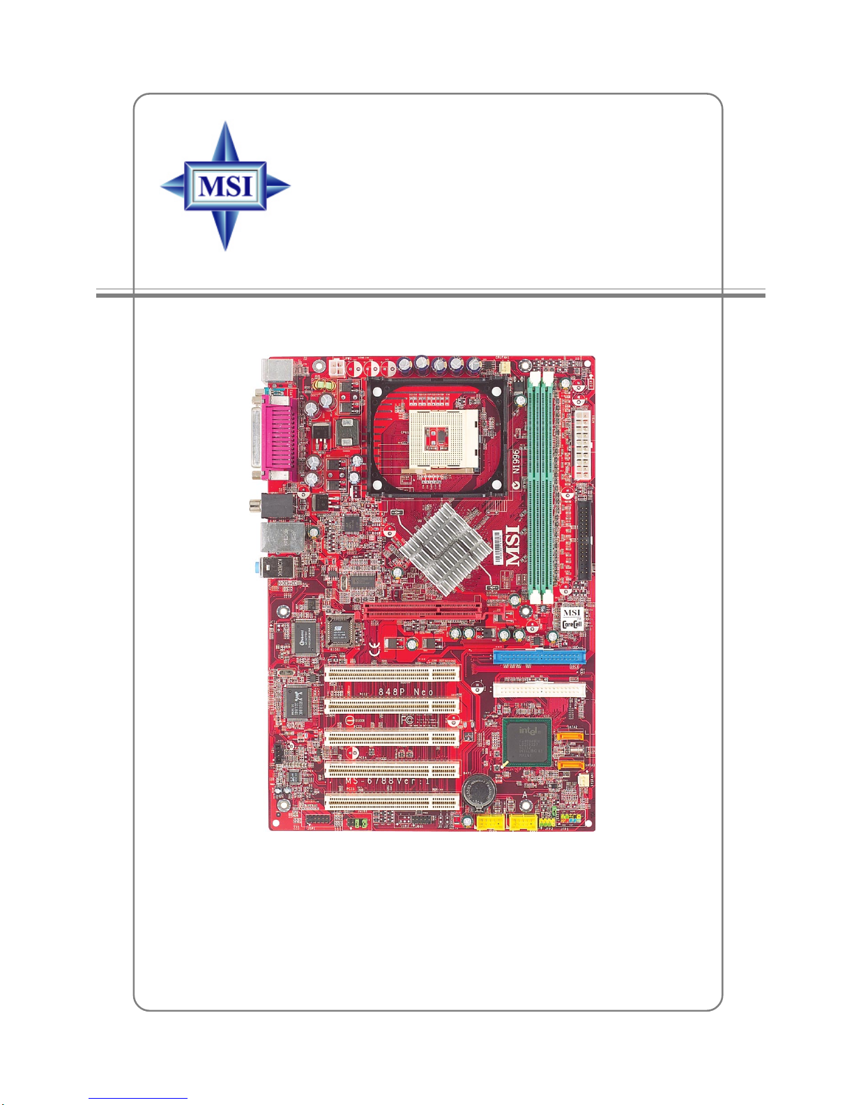
vii
Entering Setup......................................................................................3-3
Control Keys ................................................................................. 3-3
Getting Help ..................................................................................3-3
The Main Menu ...................................................................................3-4
Standard CMOS Features ....................................................................3-6
Advanced BIOS Features ....................................................................3-8
Advanced Chipset Features............................................................... 3-12
Power Management Features............................................................. 3-14
PNP/PCI Configurations..................................................................... 3-18
Integrated Peripherals ........................................................................ 3-21
PC Health Status ................................................................................ 3-25
Frequency/Voltage Control ................................................................ 3-26
Set Supervisor/User Password........................................................... 3-30
Load High Performance/BIOS Setup Defaults.................................... 3-31
Appendix:Using4-or6-ChannelAudioFunction ....................................A-1
Installing the Audio Driver .................................................................A-2
Installation for Windows 98SE/ME/2000/XP ................................A-2
Software Configuration .......................................................................A-4
Sound Effect .................................................................................A-4
Equalizer .......................................................................................A-6
Speaker Configuration..................................................................A-7
Speaker Test .................................................................................A-8
HRTFDemo ..................................................................................A-9
General .......................................................................................A-10
Using 2-, 4-, & 6- Channel Audio Function .......................................A-11

1-1
Getting Started
Chapter 1. Getting
Started
Thank you for choosing the 848P Neo (MS-6788) v1.X
ATX mainboard. The 848P Neo is based on Intel®848P and
ICH5 chipsets for optimal system efficiency. Designed to fit the
advanced Intel®Pentium®4 processors in 478 pin package, the
848P Neo delivers a high performance and professional desktop
platform solution.
Getting Started

1-2
MS-6788 ATX Mainboard
Mainboard Specifications
CPU
hSupports Intel®P4 Northwood (Socket 478) processors.
hFSB 400MHz/533MHz/800MHz depending on the North Bridge integrated.
hSupports up to 3.2GHz or higher speed P4 processor.
Chipset
hIntel® 848P chipset
- Supports 400/533/800MHz Intel NetBurst micro-architecture bus.
- Supports AGP 8X/4X at 0.8V (AGP 3.0) or 4X at 1.5V (not support 3.3V)
interface.
-SupportsPC2100/PC2700/PC3200memory.
hIntel®ICH5 chipset
- 8 Hi-Speed USB ports (USB2.0/1.1) controller, 480Mb/sec.
- 2 Serial ATA/150 ports.
- 2 channel Ultra ATA 100 bus Master IDE controller.
- PCI Master v2.3.
- I/O APIC.
- Supports both ACPI and legacy APM power management.
MainMemory
hSupports two 64-bit wide DDR data channels.
hAvailable bandwidth up to 3.2 GB/s (DDR 400) for single-channel mode.
hSupports two unbuffered DIMM of 2.5 Volt DDR SDRAM.
hh
hh
hSupports up to 2GB memory size without ECC.
hh
hh
hSupports only x8, x16 DDR devices with 4-bank.
Slots
hOne AGP slot supports 8x/4x at 0.8V (AGP 3.0) or 4x at 1.5V (3.3V not
supported).
hFive 32-bit v2.3 Master PCI bus slots (support 3.3v/5v PCI bus interface).
On-Board IDE
hDual Ultra DMA 66/100 IDE controllers integrated in ICH5.
- Supports PIO, Bus Master operation modes.
- Can connect up to four Ultra ATA drives.
hSerial ATA/150 controller integrated in ICH5.
- Up to 150MB/sec transfer rate.
- Can connect up to 2 Serial ATA drives.

1-3
Getting Started
On-BoardPeripherals
hOn-Board Peripherals include:
- 1 floppy port supports 2 FDDs with 360K, 720K, 1.2M, 1.44M and
2.88Mbytes
- 1 serial port COM1
- 1 parallel port supports SPP/EPP/ECP mode
- 8 USB 2.0 ports (Rear * 4/ Front * 4)
- 1 Line-In/Line-Out/Mic-In port
- 1 RJ45 LAN jack (Optional)
- 1 RCA SPDIF Out
Audio
hAC’97 link controller integrated in ICH5.
h6 channels software audio codec ALC655.
- Compliance with AC97 v2.2 Spec.
- Meet PC2001 audio performance requirement.
LAN(Optional)
hRealtek® 8110S/8100C Dual layout.
- Integrated Fast Ethernet MAC and PHY in one chip.
- Supports 10Mb/s, 100Mb/s and 1000Mb/s (1000Mb/s is only for Realtek
8110S) auto-negotiation operation.
- Compliant with PCI v2.2.
- Supports ACPI Power Management.
BIOS
hThe mainboard BIOS provides “Plug & Play” BIOS which detects the
peripheral devices and expansion cards of the board automatically.
hThe mainboard provides a Desktop Management Interface (DMI) function
which records your mainboard specifications.
Dimension
hATX Form Factor: 30.5 cm (L) x 21.0 cm (W).
Mounting
h6 mounting holes.

1-4
MS-6788 ATX Mainboard
Mainboard Layout
848P Neo (MS-6788 v1.X) ATX Mainboard
Intel
848P
chipset
SYSFAN1
CPUFAN1
JSP1
JAUD1
JDB1
ATX Power
Supply
IDE2
IDE1
Winbond
W83627THF
Realtek
8110S/8100C
Top : mouse
Bottom:keyboard
T:LAN jack (Optional)
B:USB ports
T:SPDIF Out
B:USB ports
CD1
JPW1
JBAT1
Codec
T:Line-In
M:
B:Mic
Line-Out
FDD1
AGPSlot
JUSB2 JUSB3 JFP1
SATA1
SATA2
JFP2
BATT
+
ICH5
PCI Slot 5
PCI Slot 4
PCI Slot 3
PCI Slot 2
PCI Slot 1
DIMM1
DIMM2
BIOS

1-5
Getting Started
MSI Special Features
Color Management
MSI has a unified color management rule for some connectors on the
mainboards, which helps you to install the memory modules, expansion cards
and other peripherals devices more easily and conveniently.
hMemory DDR DIMMs: light green
hIntel spec IDE ATA66/100 connector: 1st IDE is blue, 2nd IDE is
white
hSerial ATA150 connector: orange
hAGP 8X slot: red
hUSB 2.0 connector: yellow
hFront panel connector JFP1 : HDD LED is red, Reset Switch is blue,
Power Switch in black, Power LED is light green.
hFront panel connector JFP2: Power LED is light green.
Memory DDR DIMMs
Front Panel connector JFP2
USB 2.0 connector
AGP 8X Slot
Intel spec IDE ATA66/100 connectors:
1st IDE: blue/2nd IDE: white
Front Panel connector JFP1
Serial ATA150 connectors

1-6
MS-6788 ATX Mainboard
CoreCenter
CoreCenter (TM)- contains OC Menu panel, users can determine their
processor and memory type to optimize its memory capacity. This all-in-one
hardware console is advanced combination of the popular PC Alert and Fuzzy
Logic. Including powerful function with hardware monitor, system alert and
instinctive UI of overclocking, CoreCenter is just like your PC doctor that can
detect, view and adjust the PC hardware and system status during real time
operation.
In the left side it shows the current system status including the Vcore, 3.
3V, +5V and 12V. In the right side it shows the current PC hardware status such
as the CPU & system temperatures and all fans speeds.
When you click the red triangles in the left and right sides, two sub-
menus will open for users to overclock, overspec or to adjust the thresholds of
system to send out the warning messages. If you click the Core Center button
in the top, a screen pops up for you to choose the “Auto mode” or “User
mode” of CPU fan.

1-7
Getting Started
Left-wing:Currentsystem status
In the left sub-menu, you can configure the settings of FSB, Vcore,
Memory Voltage and AGP Voltage by clicking the radio button in front of each
item and make it available (the radio button will be lighted as yellow when
selected), use the “+” and “-” buttons to adjust, then click “OK” to apply the
changes. Then you can click Save to save the desired FSB you just configured.
Also you may click Auto to start testing the maximal CPU overclocking
value, The CPU FSB will automatically increase the testing value until the PC
reboots. Or you may click Default to restore the default values.
Right-wing:PChardwarestatusduringrealtime operation
In the right sub-menu, you can configure the PC hardware status such as
CPU & system temperatures and fan speeds. You may use the scroll bars to
adjust each item, then click “OK” to apply the changes. The values you set for
the temperatures are the maximum thresholds for the system for warnings, and
the value for fan speeds are the minimum thresholds.
Top-side:Usermode/Automode
Here you may adjust the CPU fan speed. If you choose User mode, you
may adjust the CPU fan speed in 8 different modes, from Stop to Full speed.
OCMenu
The exclusive OC Menu is fully de-
veloped to support DDR400+ memory
modules. By comprehensive validation
of over 67 DDR400+ memory modules,
MSI concluded best parameters for
DRAM voltage, Vio and other BIOS
settings. You can select DDR433,
DDR450, DDR466 and DDR500 from
DRAM frequency in BIOS setting. Or
you can just click on OC Menu button
to configure in the OC Menu at
CoreCenter. OC Menu will adjust the
necessary parameters of voltage and fre-
quency simultaneously. The only limita-
tion was the margin of processor from overclocking.

1-8
MS-6788 ATX Mainboard
Live Monitor™
The Live Monitor™ is a tool used to schedule the search
for the latest BIOS/drivers version on the MSI Web site. To use
the function, you need to install the “MSI Live Update 3”
application. After installation, the “MSI Live Monitor” icon (as
shown on the right) will appear on the screen. Double click this
icon to run the application.
Double click the “MSI Live Monitor” icon at the lower-right corner
of the taskbar, and the following dialog box will appear. You can specify how
often the system will automatically search for the BIOS/drivers version, or
change the LAN settings right from the dialog box.
You can right-click the MSI Live Monitor icon to perform the functions
listed below:
zz
zz
zAuto Search – Searches for the BIOS/drivers version you need immediately.
zz
zz
zView Last Result – Allows you to view the last search result if there is any.
zz
zz
zPreference – Configures the Search function, including the Search schedule.
zz
zz
zExit – Exits the Live Monitor™ application.
zz
zz
zFAQ – Provides a link to a database which contains various possible questions
about MSI's products for users to inquire.

1-9
Getting Started
Live BIOS™/Live Driver™
The Live BIOS™/Live Driver™ is a tool used to detect
and update your BIOS/drivers online so that you don’t need to
search for the correct BIOS/driver version throughout the whole
Web site. To use the function, you need to install the “MSI
Live Update 3” application. After the installation, the “MSI
Live Update 3” icon (as shown on the right) will appear on the
screen.
Double click the “MSI Live Update 3” icon, and the following screen will
appear:
Five buttons are placed on the left column of the screen. Click the desired
button to start the update process.
ØLive BIOS – Updates the BIOS online.
ØLive Driver – Updates the drivers online.
ØLive VGA BIOS – Updates the VGA BIOS online.
ØLive VGA Driver – Updates the VGA driver online.
ØLive OSD – Updates the firmware of the OSD products online.
ØLive Utility – Updates the utilities online.
If the product you purchased does not support any of the functions listed
above, a “sorry” message is displayed. For more information on the update
instructions, insert the companion CD and refer to the “Live Update Guide”
under the “Manual” Tab.

1-10
MS-6788 ATX Mainboard
Red Green
D-Bracket™ 2 (Optional)
D-Bracket™ 2 is a USB bracket integrating four Diagnostic LEDs, which
use graphic signal display to help users understand their system. The LEDs
provide up to 16 combinations of signals to debug the system. The 4 LEDs can
detect all problems that fail the system, such as VGA, RAM or other failures.
This special feature is very useful for overclocking users. These users can use
the feature to detect if there are any problems or failures. D-Bracket™ 2 supports
both USB 1.1 & 2.0 spec.
D-Bracket™ 2 Description
System Power ON
- The D-LED will hang here if the processor is damaged or
not installed properly.
Early Chipset Initialization
Memory Detection Test
-Testing onboard memory size. The D-LED will hang if the
memory module is damaged or not installed properly.
Decompressing BIOS image to RAM for fast booting.
Initializing Keyboard Controller.
Testing VGA BIOS
- This will start writing VGA sign-on message to the screen.
D-Bracket™ 2
1 2
3 4
12
34

1-11
Getting Started
D-Bracket™ 2 Description
Processor Initialization
- This will show information regarding the processor (like
brand name, system bus, etc…)
Testing RTC (Real Time Clock)
Initializing Video Interface
- This will start detecting CPU clock, checking type of video
onboard. Then, detect and initialize the video adapter.
BIOS Sign On
- This will start showing information about logo, processor
brand name, etc….
Testing Base and Extended Memory
- Testing base memory from 240K to 640K and extended
memory above 1MB using various patterns.
Assign Resources to all ISA.
Initializing Hard Drive Controller
- This will initialize IDE drive and controller.
Initializing Floppy Drive Controller
- This will initializing Floppy Drive and controller.
Boot Attempt
- This will set low stack and boot via INT 19h.
Operating System Booting

1-12
MS-6788 ATX Mainboard
S-Bracket(Optional)
S-Bracket is a bracket which provides 2 SPDIF jacks for digital audio
transmission and 2 analog Line-Out connectors for additional 4-channel analog
audio output. With the S-Bracket, your system will be able to perform 6-
channel audio operation for wonderful surround sound effect, or connect to
Sony & Philips Digital Interface (SPDIF) speakers for audio transmission with
better quality.
The S-Bracket offers two types of SPDIF connectors: one for optical
fiber and the other for coaxial connection. Select the appropriate one to meet
your need. For more information on S-Bracket, refer to Appendix. Using 4- or
6-Channel Audio Function.
CPUThermalProtection
Aimed to prevent the CPU from overheating, MSI has developed a CPU
Thermal Protection mechanism for Intel®CPU platform. This CPU Thermal
Protection mechanism works on a thermal signal sensor. If the mechanism
senses an abnormal temperature rise, it will automatically shut down the system
and the CPU temperature will then drop down and resume normal. With this
unique feature, users can better protect their CPU. Please note that this feature
is for Intel® Pentium CPU only.
S-Bracket
SPDIF jack (optical) SPDIF jack (coaxial)
Analog Line-Out jacks

1-13
Getting Started
RoundCable(Optional)
Round cable is an enhanced cable for PCI IDE and Ultra DMA controller.
It has the following benefits:
hData transfer rate started by 133MB/s
hBackwardcompatibility(ATA33/66/100/133)
hHigher performance than traditional Flat cable (data rate)
hImproved data robustness
hBetter airflow due to thinner ATA/133 cable
Connect to the system
connectors on the mainboard.
Connect to the slave drive.
Connect to the master drive.
Connect one end to the
floppy disk drive
connector (FDD1) and
the other end to the
standard floppy disk.
This manual suits for next models
3
Table of contents
Other MSI Motherboard manuals

MSI
MSI NF750-G55 - Motherboard - ATX User manual

MSI
MSI Z77A-G45 GAMING series User manual

MSI
MSI G965 Neo2 Series User manual

MSI
MSI MS-6187 User manual

MSI
MSI MS-7357 (V1.X) User manual

MSI
MSI MS-6382 User manual

MSI
MSI Z77A-G43 GAMING User manual

MSI
MSI MS-7641 User manual

MSI
MSI MAG B460 TORPEDO User manual

MSI
MSI K9AGM Series User manual

MSI
MSI MAG Z790 TOMAHAWK WIFI User manual

MSI
MSI Z490-A PRO User manual

MSI
MSI K7N2 Delta Series Instructions for use

MSI
MSI Bg Bang-XPower II User manual

MSI
MSI MS-6322M User manual

MSI
MSI 870S-C45 Series User manual

MSI
MSI MS-6577 User manual

MSI
MSI 870-C45 Series User manual

MSI
MSI MS-98F3 User manual

MSI
MSI MS-7204 User manual