MSI Intel 700 BIOS Series User manual

1
Intel 700 series BIOS
USER GUIDE
Motherboard

2Contents
Contents
UEFI BIOS............................................................................................................... 3
UEFI advantages..................................................................................................... 3
Incompatible UEFI cases........................................................................................ 3
How to find the BIOS version? .......................................................................... 3
BIOS Setup ............................................................................................................. 4
Entering BIOS Setup............................................................................................... 4
Function key...................................................................................................... 4
BIOS Setting Mode.................................................................................................. 5
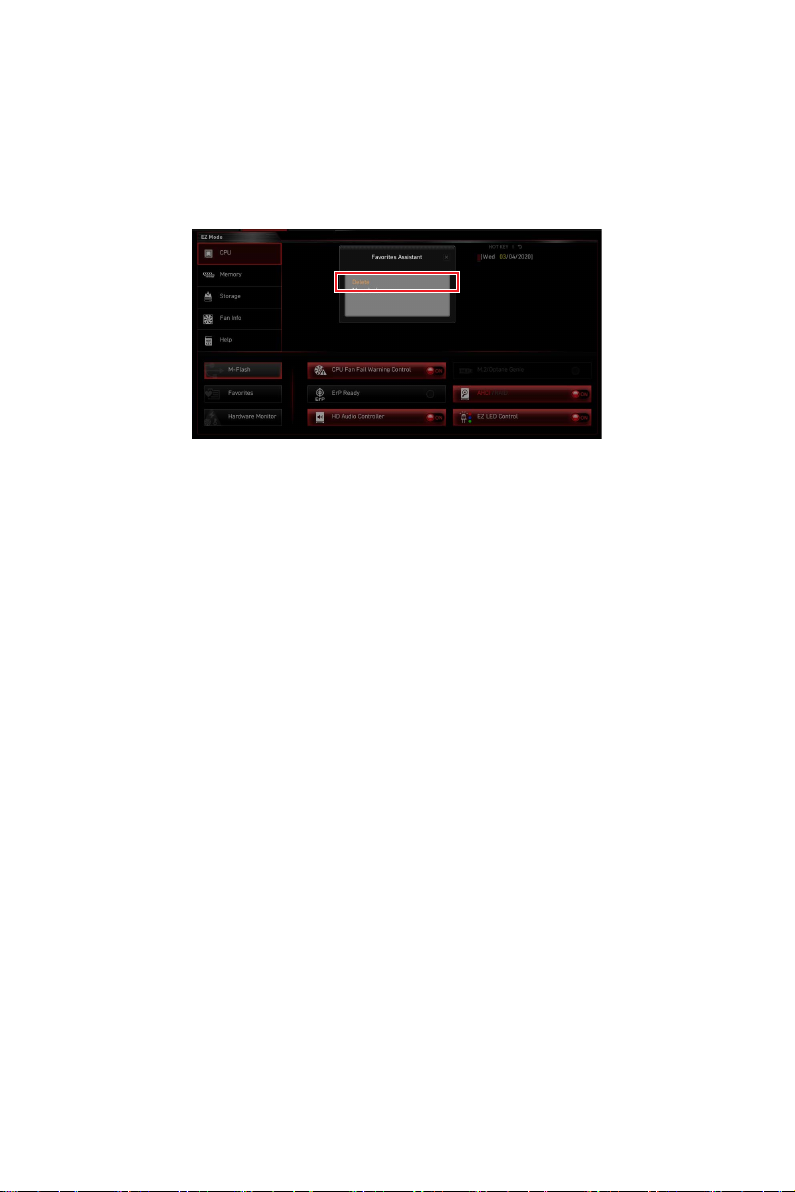
EZ Mode .................................................................................................................. 5
Advanced Mode .................................................................................................... 10
SETTINGS Menu ................................................................................................... 11
System Status ................................................................................................. 11
Advanced......................................................................................................... 12
Boot ................................................................................................................. 26
Security ........................................................................................................... 28
Save & Exit ...................................................................................................... 32
OC Menu................................................................................................................ 33
M-FLASH Menu .................................................................................................... 65
OC PROFILE Menu................................................................................................ 66
HARDWARE MONITOR Menu ............................................................................... 67
Adjusting fans ................................................................................................. 68
Resetting BIOS...................................................................................................... 69
Updating BIOS....................................................................................................... 69
Updating BIOS with M-FLASH ....................................................................... 69
Updating the BIOS with MSI Center................................................................ 70
Updating BIOS with Flash BIOS Button .......................................................... 70
Notices ................................................................................................................. 71
Copyright............................................................................................................... 71
Revision History.................................................................................................... 71

3
UEFI BIOS
UEFI BIOS
MSI UEFI BIOS is compatible with UEFI (Unified Extensible Firmware Interface)
architecture. UEFI has many new functions and advantages that traditional BIOS
cannot achieve, and it will completely replace BIOS in the future. The MSI UEFI
BIOS uses UEFI as the default boot mode to take full advantage of the new chipset’s
capabilities. However, it still has a CSM (Compatibility Support Module) mode to be
compatible with older devices. That allows you to replace legacy devices with UEFI
compatible devices during the transition.
⚠
Important
The term BIOS in this user guide refers to UEFI BIOS unless otherwise noted.
UEFI advantages
∙Fast booting - UEFI can directly boot the operating system and save the BIOS self-
test process. And also eliminates the time to switch to CSM mode during POST.
∙Supports for hard drive partitions larger than 2 TB.
∙Supports more than 4 primary partitions with a GUID Partition Table (GPT).
∙Supports unlimited number of partitions.
∙Supports full capabilities of new devices - new devices may not provide backward
compatibility.
∙Supports secure startup - UEFI can check the validity of the operating system to
ensure that no malware tampers with the startup process.
Incompatible UEFI cases
∙32-bit Windows operating system - this motherboard supports only Windows 10/
Windows 11 64-bit operating system.
∙Older graphics card - the system will detect your graphics card. When display a
warning message There is no GOP (Graphics Output protocol) support detected in this
graphics card.
⚠
Important
We recommend that you to replace with a GOP/UEFI compatible graphics card or
using integrated graphics from CPU for having normal function.
How to find the BIOS version?
After entering the BIOS, find the BIOS version at the top of the screen.
MB:
CPU:
Memory Size:
BIOS Ver:
BIOS Build Date:

4BIOS Setup
BIOS Setup
The default settings offer the optimal performance for system stability in normal
conditions. You should always keep the default settings to avoid possible system
damage or failure booting unless you are familiar with BIOS.
⚠
Important
∙
The BIOS setup screens, options and settings in this manual are for reference only
and may vary from the motherboard you purchased. Please refer to the actual BIOS
version of your system for detailed screens, settings and options.
∙
BIOS items are continuously updated for better system performance. Therefore, the
description may be slightly different from the latest BIOS and should be for reference
only. You could also refer to the HELP information panel for the BIOS item description.
∙
The BIOS options and settings for each motherboard may vary slightly with the BIOS
version, please refer to the actual BIOS of your system for settings and options.
Entering BIOS Setup
Press Delete key, when the Press DEL key to enter Setup Menu, F11 to enter Boot
Menu message appears on the screen during the boot process.
Function key
F1: General Help list
F2: Add/ Remove a favorite item
F3: Enter Favorites menu
F4: Enter CPU Specifications menu
F5: Enter Memory-Z menu
F6: Load optimized defaults
F7: Switch between Advanced mode and EZ mode
F8: Load Overclocking Profile
F9: Save Overclocking Profile
F10: Save Change and Reset*
F12: Take a screenshot and save it to USB flash drive (FAT/ FAT32 format only).
Ctrl+F: Enter Search page
* When you press F10, a confirmation window appears and it provides the modification
information. Select between Yes or No to confirm your choice.

5
BIOS Setup
BIOS Setting Mode
It provides two modes for you to configure BIOS: EZ mode and Advanced mode. Please
press F7 to switch between these two modes.
EZ Mode
At EZ mode, it provides the basic system information and allows you to configure the
basic setting. To configure the advanced BIOS settings, please enter the Advanced
Mode by pressing the Setup Mode switch or F7 function key.
XMP/ iEXPO Profile
Component
Information
System
information
Boot device
priority bar
Function
buttons
Language
GAME BOOST/
CREATOR
GENIE
BIOS Search
Screenshot Smart Button
Setup Mode switch
M-Flash
Hardware
Monitor
Favorites
∙GAME BOOST - click on it to toggle the GAME BOOST for overclocking. This function
is only available when both of the motherboard and CPU are supporting this function.
⚠
Important
Please don’t make any changes in OC menu and don’t load defaults to keep the
optimal performance and system stability after activating the GAME BOOST function.
∙CREATOR GENIE - click on it to toggle the CREATOR GENIE for performance
optimization.
⚠
Important
Please don’t make any changes in OC menu and don’t load defaults to keep the
optimal performance and system stability after activating the CREATOR GENIE
function.
∙XMP/ iEXPO Profile - allows you to select the XMP/ iEXPO profile for memory to
overclock. This function is only available when the system, memory and CPU are
supporting this function.

6BIOS Setup
∙Setup Mode switch - press this tab or the F7 key to switch between Advanced mode
and EZ mode.
∙Screenshot - click on this tab or the F12 key to take a screenshot and save it to USB
flash drive (FAT/ FAT32 format only).
∙BIOS Search - click on this tab or the Ctrl+F keys to enter the search page. It allows
you to search by BIOS item name. Move the mouse over a blank space and right click
the mouse to exit the search page.
⚠
Important
In search page, only the F6, F10 and F12 function keys are available.
∙Smart Button - it provides 4 function modes to be achieved by reset button of the
computer chassis or by the smart button on the motherboard.
▪Reset - press the reset/ smart button to reset the system.
▪Mystic Light on/ off - press the reset/ smart button to turn on/ off all the
onboard LEDs.
⚠
Important
The Mystic Light on/ off function mode is unavailable when the LED_SW1 (EZ LED
Control) switch turns OFF.
▪Safe Boot - click the reset/ smart button and start the system simultaneously to
boot in Safe Boot mode. The system will boot with default and lower the PCIe (from
CPU) mode.
▪Turbo Fan - press the reset/ smart button for all fans to operate full speed or
default speeds.
▪Configuring Smart Button
1. Click on Smart Button and select a function mode.
2. Press F10 to save the change and select Yes to restart the system.

7
BIOS Setup
∙Language - allows you to select language of BIOS setup.
∙System information - shows the CPU/ DDR speed, CPU/ MB temperature, MB/ CPU
type, memory size, CPU/ DDR voltage, BIOS version and build date.
∙Boot device priority bar - you can move the device icons to change the boot priority.
The boot priority from high to low is left to right.
∙Component Information - click on the CPU, Memory, Storage,Fan Info and Help
buttons to show the information of the connected device.
∙Function buttons - enable or disable the BIOS functions by clicking on these
buttons. The button shows ON after enableing the function .
▪CPU Fan Fail Warning Control - enables or disables to show the CPU fan fail
warning message on the POST.
▪VMD (RAID) - enables or disables the Intel VMD for RAID function.
▪fTPM 2.0 - enables or disables the firmware TPM control.
▪Thunderbolt Control - enables or disables the thunderbolt I/O device support.
▪ErP Ready - enables or disables the system power consumption according to
ErP regulation.
▪Debug Code LED Control - enables or disables the debug code LED.
▪EZ LED Control - turns on or turns off all the LEDs of motherboard.
▪HD Audio Controller - enables or disable the HD audio controller.
∙M-Flash - click on this button to enter the M-Flash menu that provides the way to
update BIOS with a USB flash drive.
∙Hardware Monitor - click on this button to enter the Hardware Monitor menu that
allows you to manually control the fan speed by percentage.

8BIOS Setup
∙Favorites - click on this button or press the F3 key to show the Favorites window.
It provides 5 menus for you to create personal BIOS menu where you can save and
access favorite/ frequently-used BIOS setting items.
▪To add a BIOS item to a favorite menu
1. Select a BIOS item not only on BIOS menu but also on search page.
2. Right-click or press F2 key.
3. Choose a favorite page and click on OK.

9
BIOS Setup
▪To delete a BIOS item from favorite menu
1. Select a BIOS item on favorite menu.
2. Right-click or press F2 key.
3. Choose Delete and click on OK.

10 BIOS Setup
Advanced Mode
Press Setup Mode switch or F7 function key can switch between EZ Mode and
Advanced Mode in BIOS setup.
BIOS menu
selection
Menu display
BIOS menu
selection
∙BIOS menu selection - the following options are available:
▪SETTINGS - allows you to specify the parameters for chipset and boot devices.
▪OC - allows you to adjust the frequency and voltage. Increasing the frequency
may get better performance.
▪M-FLASH - provides the way to update BIOS with a USB flash drive.
▪OC PROFILE - allows you to manage overclocking profiles.
▪HARDWARE MONITOR - allows you to set the speeds of fans and monitor
voltages of system.
▪BETA RUNNER - provides the beta functions or features for the user who craves
the new experience. However, we welcome and expect you to give us some more
feedback on user experience. That will be helpful in improving the functions.
▪SECURITY - allows you to set the administrator password and the user password
for system security.
∙Menu display - provides BIOS setting items and information to be configured.

11
BIOS Setup
SETTINGS Menu
This menu allows you to specify the parameters for system, chipset and boot devices.
System Status
The System Status sub-menu allows you to set the system clock and view system
information.
▶System Date
Sets the system date. Use tab key to switch between date elements.
The format is <day> <month> <date> <year>.
<day> Day of the week, from Sun to Sat, determined by BIOS. Read-only.
<month> The month from Jan. through Dec.
<date> The date from 1 to 31 can be keyed by numeric function keys.
<year> The year can be adjusted by users.
▶System Time
Sets the system time. Use tab key to switch between time elements. The time format
is <hour> <minute> <second>.

12 BIOS Setup
▶SATA PortX/ M2_X/ U2_X
Shows the information of connected SATA/ M.2/ U.2 devices.
⚠
Important
If the connected SATA/ M.2/ U.2 device is not displayed, turn off computer and
re-check SATA/ M.2/ U.2 cable and power cable connections of the device and
motherboard.
▶System Information
Shows detailed system information, including CPU type, BIOS version, and Memory
(read only).
▶DMI Information
Shows system information, desktop Board Information and chassis Information. (Read
only).
Advanced
The Advanced sub-menu allows you to adjust and set the parameters and behaviors of
PCIe, ACPI, integrated peripherals, integrated graphics, USB, power management and
Windows.

13
BIOS Setup
▶PCIe/PCI Sub-system Settings
Sets PCI, PCI express interface protocol and latency timer. Press Enter to enter the
sub-menu.
▶M.2_1 - Max Link Speed
Sets PCI Express protocol for M2_1slot to match dierent installed M.2 devices.
[Auto] This item will be congured automatically by BIOS.
[Gen1] Enables PCIe Gen1 support only.
[Gen2] Enables PCIe Gen2 support only.
[Gen3] Enables PCIe Gen3 support only.
[Gen4] Enables PCIe Gen4 support only.
[Gen5] Enables PCIe Gen5 support only.
▶PCIE_E1 - Max Link Speed
Sets PCI Express protocol for PCI_E1 slot to match dierent installed PCIe devices.
[Auto] This item will be congured automatically by BIOS.
[Gen1] Enables PCIe Gen1 support only.
[Gen2] Enables PCIe Gen2 support only.
[Gen3] Enables PCIe Gen3 support only.
[Gen4] Enables PCIe Gen4 support only.
[Gen5] Enables PCIe Gen5 support only.
▶PCIE_E2 - Max Link Speed
Sets PCI Express protocol for PCI_E2 slot to match dierent installed PCIe devices.
[Auto] This item will be congured automatically by BIOS.
[Gen1] Enables PCIe Gen1 support only.
[Gen2] Enables PCIe Gen2 support only.
[Gen3] Enables PCIe Gen3 support only.
[Gen4] Enables PCIe Gen4 support only.
[Gen5] Enables PCIe Gen5 support only.

14 BIOS Setup
▶CPU PCIe Lanes Configuration
Congures the PCIe lanes from CPU for adapting multiple PCIe devices usages.
▶PCI Latency Timer
Sets latency timer for PCI interface device.
▶Max TOLUD
Sets the maximum TOLUD (Top of Low Usable DRAM) value.
▶Above 4G memory/ Crypto Currency mining
Enables this item to allow more memory address conguration space (requires 64
bit OS) with another optimized setting for better device compatibility and it might
slightly aect the eciency of PCIe-based devices.
[Enabled] Allows you to utilize more than 4x GPUs.
[Disabled] Disables this function.
▶Re-Size BAR Support
Enables or disables the Resize BAR (Base Address Register) support. It is only
available if the system supports 64-bit PCI/ PCIe decoding. If the system supports
64-bit PCI/ PCIe decoding, please enable this item for compatible PCIe devices.
▶Native PCIE Enable
Enables or disables the PCIE native control.
▶Native ASPM
If enabled, the native ASPM will be controlled by OS. If disabled, the native ASPM
will be controlled by BIOS.
▶PCIe/PCI ASPM Settings
Sets PCIe/ PCI ASPM (Active State Power Management) state for dierent installed
devices. Press Enter to enter the sub-menu.
▶PEG 0 ASPM
Sets PCI Express ASPM (Active State Power Management) state for power saving.
▶PEG 1 ASPM
Sets PCI Express ASPM (Active State Power Management) state for power saving.
▶PEG 2 ASPM
Sets PCI Express ASPM (Active State Power Management) state for power saving.
▶PEG 3 ASPM
Sets PCI Express ASPM (Active State Power Management) state for power saving.
▶PCI Express Root Port 1 ASPM
Sets PCI Express ASPM (Active State Power Management) state for power saving.
▶PCI Express Root Port 5 ASPM
Sets PCI Express ASPM (Active State Power Management) state for power saving.

15
BIOS Setup
▶PCI Express Root Port 7 ASPM
Sets PCI Express ASPM (Active State Power Management) state for power saving.
▶PCI Express Root Port 8 ASPM
Sets PCI Express ASPM (Active State Power Management) state for power saving.
▶PCI Express Root Port 9 ASPM
Sets PCI Express ASPM (Active State Power Management) state for power saving.
▶PCI Express Root Port 21 ASPM
Sets PCI Express ASPM (Active State Power Management) state for power saving.

16 BIOS Setup
▶ACPI Settings
Sets ACPI parameters of onboard power LED behaviors. Press Enter to enter the sub-
menu.
▶Power LED
Sets shining behaviors of the onboard Power LED.
[Dual Color] The power LED turns to another color to indicate the S3 state.
[Blinking] The power LED blinks to indicate the S3 state.
▶CPU Over Temperature Alert
Enables or disables the CPU overheating alert sound and message when CPU
temperature is over 80 and 94 degrees centigrade.
▶Temperature Display On Debug Code
Selects a thermal detection point and then the detected temperature will display
on the debug code LED when the system is on.

17
BIOS Setup
▶Integrated Peripherals
Sets integrated peripherals' parameters, such as LAN, HDD, USB and audio. Press
Enter to enter the sub-menu.
▶VGA Detection
Allows the system to detect if there is any discrete VGA card or integrated graphics
unit.
▶Onboard LAN Controller
Enables or disables the onboard LAN controller.
▶LAN Option ROM
Enables or disables the legacy network Boot Option ROM for detailed settings. This
item will appear when Onboard LAN Controller is enabled.
[Enabled] Enables the onboard LAN Boot ROM.
[Disabled] Disables the onboard LAN Boot ROM.
▶Network Stack
Sets UEFI network stack for optimizing IPv4 / IPv6 function. This item is available
when Onboard LAN Controller is enabled.
[Enabled] Enables UEFI network stack.
[Disabled] Disables UEFI network stack.
▶Ipv4 PXE Support
When Enabled, the system UEFI network stack will support Ipv4 protocol. This item
will appear when Network Stack is Enabled.
[Enabled] Enables the Ipv4 PXE boot support.
[Disabled] Disables the Ipv4 PXE boot support.
▶Ipv6 PXE Support
When Enabled, the system UEFI network stack will support Ipv6 protocol. This item
will appear when Network Stack is enabled.
[Enabled] Enables the Ipv6 PXE boot support.
[Disabled] Disables the Ipv6 PXE boot support.

18 BIOS Setup
▶BT Tile Mode
If enabled, this item allows you to locate your PC by the Tile APP on your
smartphone.
▶Onboard CNVi Module Control
Enables or disables the functions (WiFi and Bluetooth) of the Intel CNVi module.
▶Onboard Wi-Fi/BT Module Control
Enables or disables the onboard WiFi and Bluetooth functions.
▶Onboard IEEE1394 Controller
Enables or disables the onboard IEEE1394 controller.
▶RAID Configuration (Intel VMD)
Enables or disables the RAID conguration. Press Enter to enter the sub-menu.
▶Enable VMD Global Mapping
Enables or disables Intel VMD mapping. Intel VMD enables direct control and
management of NVMe SSDs from the PCIe bus without additional hardware
adapters.
▶RAID0
Enables or disables RAID 0.
▶RAID1
Enables or disables RAID 1.
▶RAID5
Enables or disables RAID 5.
▶RAID10
Enables or disables RAID 10.
▶Intel Rapid Recovery Technology
Enables or disables Intel Rapid Recovery Technology. Intel® Rapid Recover
Technology (Intel® RRT) is a feature of Intel® Rapid Storage Technology (Intel®
RST). It uses RAID 1 (mirroring) functionality to copy data from a designated
master drive to a designated recovery drive.
▶RRT volumes can span internal and eSATA drives
Enables or disabled the RRT volumes to span internal and eSATA drives.
▶ZPODD
Enables or disabled the ZPODD (Zero Power optical disk drive).
▶SATA1 Hot Plug
Enables or disabled the SATA1 port hot plug support.
▶SATA2 Hot Plug
Enables or disabled the SATA2 port hot plug support.

19
BIOS Setup
▶SATA3 Hot Plug
Enables or disabled the SATA3 port hot plug support.
▶SATA4 Hot Plug
Enables or disabled the SATA4 port hot plug support.
▶SATA5 Hot Plug
Enables or disabled the SATA5 port hot plug support.
▶SATA6 Hot Plug
Enables or disabled the SATA6 port hot plug support.
▶SATAA Hot Plug
Enables or disabled the SATAA port hot plug support.
▶SATAB Hot Plug
Enables or disabled the SATAB port hot plug support.
▶Onboard E-SATA Controller Mode
Sets the operation mode of the onboard E-SATA controller.
▶External SATA 6GB/s Controller Mode
Sets the operation mode of the external SATA controller.
▶HD Audio Controller
Enables or disables the onboard High Denition Audio controller.
▶ Integrated Graphics Conguration
Adjusts integrated graphics settings for optimum system. Press Enter to enter the
sub-menu. This sub-menu is only available with the CPU integrate with IGP.
▶Initiate Graphic Adapter
Selects a graphics device as the primary boot device.
[IGD] Integrated Graphics Display.
[PEG] PCI-Express Graphics Device.

20 BIOS Setup
▶Integrated Graphics Share Memory
Selects a xed amount of system memory allocated to the onboard graphics. This
item will appear when an external graphics card be installed and the IGD Multi-
Monitor is enabled.
▶IGD Multi-Monitor
Enables or disables the multi-screen output from integrated graphics and external
graphics card. This item appears when Initiate Graphic Adapter set to PEG.
[Enabled] Enables multi-screen function for both integrated and external
graphics cards.
[Disabled] Disables this function.
▶Intel (R) Thunderbolt
Sets the thunderbolt device function. Press Enter to enter the sub-menu.
▶PCIE Tunneling over USB4
Enables or disables the PCI-E Tunnel protocol over USB4.
▶Discrete Thunderbolt(TM) Support
Enables or disables the thunderbolt device support.
▶Wake From Thunderbolt(TM) Device
Enables or disables the system wake up by thunderbolt device.
▶Discrete Thunderbolt(TM) Configuration
Sets the thunderbolt device conguration. Press Enter to enter the sub-menu.
▶Thunderbolt Boot Support
Enables or disables the system to boot from boot-able thunderbolt device.
▶GPIO3 Force Pwr
Sets GPIO3 to 1/0.
Table of contents
Other MSI Motherboard manuals

MSI
MSI PRO Z790-A WIFI User manual

MSI
MSI MS-7551 User manual

MSI
MSI G41M series User manual

MSI
MSI MS-7357 (V1.X) User manual

MSI
MSI Z87 MPOWER MAX User manual

MSI
MSI MEG B550 UNIFY User manual

MSI
MSI X370 XPOWER GAMING TITANIUM User manual

MSI
MSI D3050 User manual

MSI
MSI IM-HM65 User manual

MSI
MSI H170A PC MATE User manual

MSI
MSI MS-6135 User manual

MSI
MSI 880GM-P51 Series User manual

MSI
MSI MAG B650 TOMAHAWK WIFI User manual

MSI
MSI H170M PRO-VDH User manual

MSI
MSI Z490-A PRO User manual

MSI
MSI X370 SLI PLUS User manual

MSI
MSI 990FXA-GD80 series User manual

MSI
MSI MPG Z590 GAMING CARBON WIFI User manual

MSI
MSI X470 GAMING PRO User manual

MSI
MSI Z77A-GD65 GAMING series User manual