MSI LPX SI15 User manual

CHAPTER 1CHAPTER 1
CHAPTER 1CHAPTER 1
CHAPTER 1 INTRODUCTIONINTRODUCTION
INTRODUCTIONINTRODUCTION
INTRODUCTION
1-1
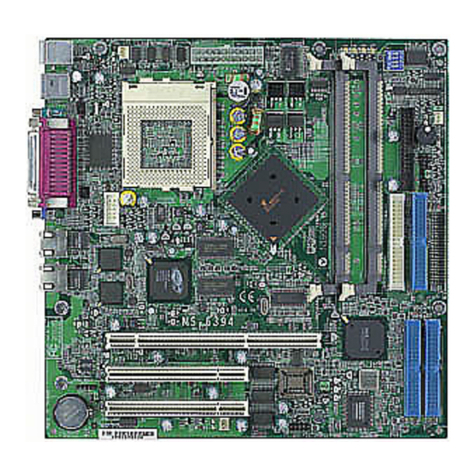
The MSI LPX SI15 mainboard is a high-performance personal computer
mainboard based on the Pentium®
processor. This mainboard supports
Intel®Pentium®
/Pentium®
with MMXTMTechnology, Cyrix®6x86/6x86L/
6x86MX, AMD®K5/K6, and IDT C6TM processors.
The mainboard utilizes the SiS®
5597 chipset, which has Built-in VGA using
UMA mode. In addition there is an on-chipset USB and IDE controller
whichsupportsIDEPIO/BusmasteroperationmodeforIDEHDD/CD-ROM.
The PIO mode supports Mode 0,1,2,3 and 4, with a transfer rate up to 22 MB
per/sec.
Chapter 1
INTRODUCTION

CHAPTER 1CHAPTER 1
CHAPTER 1CHAPTER 1
CHAPTER 1 INTRODUCTIONINTRODUCTION
INTRODUCTIONINTRODUCTION
INTRODUCTION
1.1 Mainboard Features
CPU
lSocket 7 supports Intel®
Pentium®
/Pentium®
with MMXTM technology
Processor
lTheCyrix® 6x86/6x86L/6x86MX,AMD® K5/K6andIDTC6TMprocessors
are also supported.
CacheMemory
lSupports 512K pipelined burst cache memory.
lSupports Direct Map Organization and Write-Back cache policy.
Chipset
lSiS®
5597single chip BGA package with built-in VGA.
lBuilt-in16Kb dirty SRAM.
MainMemory
lSupports two 168-pin unbuffered DIMM sockets.
lUpto 128 MBmain memory.
lSupportssymmetric or asymmetric memory.
lSupports Fast Page (FP) Mode, Extended Data Output (EDO) Mode, and
SDRAM.
Slots
lSupports riser slot.
lRiser card supports one PCI and ISA slots or two ISA slots.
lSupports 3.3V PCI cards.
On-BoardPeripherals
lOn-BoardPeripheralsinclude:
-1floppyportsupports2FDDwith360K,720K,1.2M,1.44Mand
2.88Mbytes.
- 2 serial ports (COM A & COM B).
- 1 parallel port supports EPP/ECP mode.
- 1 IrDA connector.
1-2

CHAPTER 1CHAPTER 1
CHAPTER 1CHAPTER 1
CHAPTER 1 INTRODUCTIONINTRODUCTION
INTRODUCTIONINTRODUCTION
INTRODUCTION
1-3
On-BoardIDE
lAn IDE controller on the SiS®
5597 PCI Chipset provides IDE HDD/CD-
ROM with PIO and Bus Master Operation Mode. The PIO Mode
supports modes 0, 1, 2, 3 and 4 with a transfer rate of 22 Mbytes per
second.
lSupports Multi-word DMA and Ultra DMA/33.
lSupports dual mode operation - Native & Compatibility mode.
On-BoardVGA
lOn-chip SiS®
VGA.
lSupports UMA(Untied Memory Address) 0.5MB~4MB.
Network
lConcertoI (PCB ver 1.X)
l Winbond W940 10M
l Supports 10BASE-T/TX
lConcertoII(PCBver2.X)
l Intel®
558 100M chipset
l 100BASE-T/TXLAN
l Supports wake-up on LAN
l 3K byte transmit and receiver FIFOs provide large on-chip storage of
multiple transmit and receive frames
Sound
lESS®
1869 chip .
- 3D audio effects.
-16bit full-duplex stereo.
- 16 bit address decode.
lSupports full duplex phonic mode.
lThree jack connectors: mic, line-in, and speaker.
On-BoardUSB
lSupports dual port USB(Universal Serial Bus).

CHAPTER 1CHAPTER 1
CHAPTER 1CHAPTER 1
CHAPTER 1 INTRODUCTIONINTRODUCTION
INTRODUCTIONINTRODUCTION
INTRODUCTION
BIOS
lThe system board BIOS provides “Plug & Play” BIOS which detects the
peripheral devices and expansion cards of the board automatically.
lThe system board provides a Desktop Management Interface(DMI)
function which records your system board specifications.
RTC
lNon-VolatileRTC with 256 bytes of CMOS RAM.
KeyboardConnector
lPS/2®
keyboard interface and PS/2®
mouse interface.
Dimension
lALL-IN-ONE: 25cm(L)x22.3cm(W)x4layerPCB.
Mounting
l6 mounting holes.
1-4

CHAPTER 1CHAPTER 1
CHAPTER 1CHAPTER 1
CHAPTER 1 INTRODUCTIONINTRODUCTION
INTRODUCTIONINTRODUCTION
INTRODUCTION
DIMM 1
DIMM 2
SiS
5597
Socket 7
SW 1
JV2
JG1
JFAN1 JRM1
JB2
JFP1
Power Connector
FDD
HDD2
HDD1
BIOS
JIR1
BATT
JCD1
COM B COM A
JFEAU
JCD2
JMODEM
VGA LAN LPT USB
PS/2
mouse PS/2
keyboard
MIC Line
In Speaker
Riser Card Slot
JG2
JFAN2
JGAME1
JLAN2
JSON
1.2 Mainboard Layout
MS-5150 ver 1.X
CONCERTO I
1-5

CHAPTER 1CHAPTER 1
CHAPTER 1CHAPTER 1
CHAPTER 1 INTRODUCTIONINTRODUCTION
INTRODUCTIONINTRODUCTION
INTRODUCTION
1-6
MS-5150 ver 2.X
CONCERTO II
DIMM 1
DIMM 2
SiS
5597
Socket 7
SW 1
JV2
JG1
JFAN1 JRM1
JB1
JFP1
Power Connector
FDD
HDD2
HDD1
BIOS
JIR1
BATT
JCD1
COM B COM A
JFEAU
JCD2
JMODEM
VGA LAN LPT USB
PS/2
mouse PS/2
keyboard
MIC Line
In Speaker
Riser Card Slot
JG2
JFAN2
JGAME1
JLAN2 JSON

CHAPTER 2 HARDWARE INSTALLATION
CPU
CPU
OpenLever
Pin1
Sliding
Plate
White dot/
Cut edge
Close
Lever
Chapter 2
Hardware Installation
2.1 Central Processing Unit: CPU
The MSI LPX SI15 mainboard operates with Intel®
Pentium®
/Pentium®
withMMXTM technology, Cyrix®
6x86/6x86L/6x86MX, AMD®
K5/K6 and
IDT C6TM processors. It could operate with 2.8V to 3.52V processors. The
mainboard provides a 321-pin ZIF Socket 7 for easy CPU installation, a DIP
switch (SW1) to set the proper speed for the CPU. The CPU should always
have a cooling fan attached to prevent overheating.
2-1
1. Pull the lever sideways away
from the socket. Then raise
the lever up to a 90-degree
angle.
3. Press the lever down to
complete the installation.
2. Locate Pin 1 in the socket
and look for the white dot or
cut edge in the CPU. Match
Pin 1 with the white dot/cut
edge. Then insert the CPU.
It should insert easily.
2.1-1 CPU Installation Procedure

CHAPTER 2 HARDWARE INSTALLATION
1. The DIP Switch SW1 (4, 5, and 6) is used to adjust the CPU Clock
Frequency. See the following chart to set the different Host Clock
Frequencies.
4 5 6 Clock
ON ON OFF 50MHz
OFF ON ON 55MHz
ON OFF OFF 60MHz
OFF OFF OFF 66MHz
ON OFF ON 75MHz
SW1 CPU
2. The DIP Switch SW1 (1,2, and 3) is used to set the Core/Bus (Fraction)
ratio of the CPU. The actual core speed of the CPU is the Host Clock
Frequency multiplied by the Core/Bus ratio. For example:
If CPUClock = 66MHz
Core/Bus ratio = 1.5
then CPU core speed = Host Clock x Core/Busratio
= 66MHzx1.5/2
= 100MHz
3. The PCI Bus Clock is the CPU Clock Frequency divided by 2.
2.1-2 CPU Core Speed Derivation Procedure
1 2 3 Core/BusRatio
OFF OFF OFF 1.5/3.5
ON OFF OFF 2
ON ON OFF 2.5/1.75
OFF ON OFF 3
SW1 CPU
2-2

CHAPTER 2 HARDWARE INSTALLATION
2.1-4 CPU Speed Setting: SW1
To adjust the speed of the CPU, you must know the specification of your
CPU (always ask the vendor for CPU specificaton). Then look at Table 2.1
(Intel®
Pentium®
/Pentium®
with MMXTM technology processor), Table2.2
(Cyrix®
6x86/6x86L/6x86MXprocessor),Table2.3 (AMD®
K5/K6
processor) and Table 2.4(IDT C6TM processor) for proper setting.
2-3
2.1-3 CPU Jumperless Voltage Setting: JV1(reserved)/JV2
This mainboard provides a jumperless voltage setting. The moment you
change your CPU, the BIOS will auto-detect and enter BIOS Setup menu.
Press “F10” or select “ Saveand Exit”. The system will reboot.
JV2 is short, if you’re using an Intel®
Pentium®
Overdrive®
processor.
JV2
SW1
1 2 3 4 5 6
ON ON
OFF
Speed Setting
DIP

CHAPTER 2 HARDWARE INSTALLATION
Table 2.1 Intel®
Processor
2-4
ON DIP
123 456
ON
OFF
100MHz
120MHz
133MHz
150MHz
166MHz
200MHz
ON DIP
123 456
ON
OFF
ON DIP
123 456
ON
OFF
ON DIP
123 456
ON
OFF
90MHz
CPU
Type CPU Speed
SW1
ON DIP
123 456
ON
OFF
ON DIP
123 456
ON
OFF
ON DIP
123 456
ON
OFF
ON DIP
123 456
ON
OFF
200MHz
233MHz
166MHz
ON DIP
123 456
ON
OFF
ON DIP
123 456
ON
OFF
Intel®
Pentium® Processors with MMXTM Technology
Intel®
Pentium®
Processors

CHAPTER 2 HARDWARE INSTALLATION
Table 2.2 Cyrix®
Processor
Cyrix®
processor uses PR to rate the speed of their processor based on
Intel®Pentium®processor core speed. For example, P150 (120MHz) has
150MHz core speed of Intel®Pentium®processor but has 120MHz core
speed in Cyrix®processor. Cyrix®
processor should always uses a more
powerful fan (ask vendor for proper cooling fan).
2-5
ON DIP
123 456
ON
OFF
PR166
CPU
Type CPU Speed
SW1
ON DIP
123 456
ON
OFF
PR200
Cyrix®
6x86 Processors

CHAPTER 2 HARDWARE INSTALLATION
ON DIP
123 456OFF
ON DIP
123 456
ON
OFF
ON DIP
123 456
ON
OFF
PR233
(66 x 3)
PR200
(66 x 2.5)
ON DIP
123 456
ON
OFF
ON DIP
123 456
ON
OFF
ON DIP
123 456
ON
OFF
PR200
(75 x 2)
PR233
(75 x 2.5)
PR266
(66 x 3.5)
Cyrix®
6x86MXProcessors withMMXTM Technology
(reserved)
PR166
(60 x 2.5)
ON
CPU
Type CPU Speed
SW1
2-6
ON DIP
123 456
ON
OFF
PR266
(75 x 3)

CHAPTER 2 HARDWARE INSTALLATION
Table 2.3 AMD®
Processor
AMD®
processor uses PR to rate the speed of there processor based on
Intel®Pentium®processor core speed. For example, PR133 (100MHz) has
133MHz core speed of Intel®Pentium®processor but has 100MHz core
speed in AMD®
processor.
2-7
AMD®
K6 Processors with MMXTM Technology
ON DIP
123 456
ON
OFF
ON DIP
123 456
ON
OFF
ON DIP
123 456
ON
OFF
ON DIP
123 456
ON
OFF
PR90
CPU
Type CPU Speed
SW1
ON DIP
123 456
ON
OFF
ON DIP
123 456
ON
OFF
ON DIP
123 456
ON
OFF
ON DIP
123 456
ON
OFF
ON DIP
123 456
ON
OFF
PR100
PR120
PR133
PR150
PR166
PR166
(166MHz)
PR200
(200MHz)
PR233
(233MHz)
AMD®
K5 Processors
ON DIP
123 456
ON
OFF
PR266
(266MHz)

CHAPTER 2 HARDWARE INSTALLATION
Table 2.4 IDT Processor
ON DIP
123 456
ON
OFF
150MHz
CPU
Type CPU Speed
SW1
ON DIP
123 456
ON
OFF
ON DIP
123 456
ON
OFF
180MHz
200MHz
IDT C6TM Processors
2-8

CHAPTER 2 HARDWARE INSTALLATION
2.1-5 CPU Fan Connectors: JFAN1/JFAN2
These connectors support fan with +12V. When connecting the wire to the
connector, always take note that the red wire is the positive and should be
connected to the +12V pin. The black wire should be connected to GND.
We recommend on using the JFAN2, for easy installation.
JFAN1
+12V
GND
Recommended CPU cooling fan specification:
- MetallicClip
- RPM6000
- CFM10
- +12V
- 52x52x10mm
- BallBearing
- MaximumHeatSink is3cm.
Note: Always consult vendor for proper CPU
cooling fan.
2-9
GND
JFAN2
+12V
GND

CHAPTER 2 HARDWARE INSTALLATION
2.2 External Battery Connector: JB1/ JB2
A battery must be used to retain the system board configuration in CMOS
RAM. If you use the on-board battery, you must short pins of JB1 to keep
the CMOS data.
JB1 (PCB ver 2.X)/
JB2 (PCB ver 1.X)
2-10
KEEPDATA
CLEARDATA
1
1
2
3
2
3
1
2
3

CHAPTER 2 HARDWARE INSTALLATION
2.3 Power Saving Switch Connector: JG1/
Power Saving LED Connector: JG2
Attach a power saving switch to JG1. When the switch is pressed, the
system immediately goes into suspend mode. Press any key and the system
wakes up. JG2 can be connected with LED to monitor the JG1.
When you use an ATX power supply, shorting JG1 more than 4 sec will turn
off the system.
2-11
JG2
JG1

CHAPTER 2 HARDWARE INSTALLATION
2-12
DIMM2 (Bank 2)
2.4 Memory Installation
2.4-1 Memory Bank Configuration
The mainboard provides two 168-pin unbuffered DIMM(Double In-Line
Memory) sockets to support a maximum of 128MB memory. You can use
DIMMfrom 8MB,16MB, 32MB, to 64MB.
DIMM1 (Bank 1)

CHAPTER 2 HARDWARE INSTALLATION
2-13
A. HowtoinstallaDIMMModule
1. The DIMM slot has a two Notch Key called “VOLT and DRAM” ,
so the DIMM memory module can only fit in one direction.
2. Insert the DIMM memory module vertically into the DIMM slot.
Then, push it in.
3. This will automatically close the plastic clip at the side of the
DIMM slot.
SingleSidedDIMM
DoubleSidedDIMM
VOLTDRAM
2.4-2 Memory Installation Procedures

CHAPTER 2 HARDWARE INSTALLATION
4M 1M x 4 Symmetric 10 x 10 8MB 16MB
16M 1M x 16 Symmetric 10 x 10 8MB 16MB
2M x 8 Asymmetric 11 x 10 16MB 32MB
4M x 4 Symmetric 11 x 11 32MB 64MB
64M 4M x 16 Symmetric 11 x 11 32MB 64MB
8M x 8 Asymmetric 12 x 11 64MB -
2-14
1. You can only use a 3.3v EDO and SDRAM DIMM.
2. You can only used an unbuffered DIMM.
3. To operate properly, at least one 168-pin DIMM module must be
installed.
4. DIMM1 must be populated first.
5. You canmixedEDO and SDRAM.
6. The DRAM addressing and the size supported by the mainboard is
shown below.
2.4-3 Memory Population Rule
Memory Mapping Options
DRAM
Tech. Memory
Org. Addressing Address
Size
MB/DIMM
Single
Side Double
Side
There are some SDRAM DIMM’s that will not function
properly with this mainboard. Please refer to Chapter 8:
Memory Compatibility Test for more information.
!
WARNING!
Table of contents
Other MSI Motherboard manuals

MSI
MSI MS-7036 User manual

MSI
MSI MS7797 User manual

MSI
MSI Z170A XPOWER GAMING TITANIUM EDITION User manual

MSI
MSI MS-98E1 User manual

MSI
MSI Z270 GAMING M7 User manual

MSI
MSI Z77A-G45 GAMING series User manual

MSI
MSI Z68MA-ED55 (B3) User manual

MSI
MSI 694T Pro User manual

MSI
MSI K8NNeo2-FX Series User manual

MSI
MSI Q57M-E40 Series User manual

MSI
MSI G31M3-F - Motherboard - Micro ATX User manual

MSI
MSI 760GA-P43 FX User manual

MSI
MSI B560-A PRO User manual

MSI
MSI P67A-GD65 Series User manual

MSI
MSI 655 Max User manual

MSI
MSI PRO B660-A DDR4 User manual

MSI
MSI NF725-C35 Series User manual

MSI
MSI MS-6395 User manual

MSI
MSI MS-7329 User manual

MSI
MSI MPG Z690 CARBON WIFI User manual