MSI MS-7275 User manual

i
MS-7275
MS-7275 (V1.2) Mainboard

ii
CONTENTS
Chapter 1 Getting Start .........................................................................................1-1
Mainboard Specifications ..................................................................................1-2
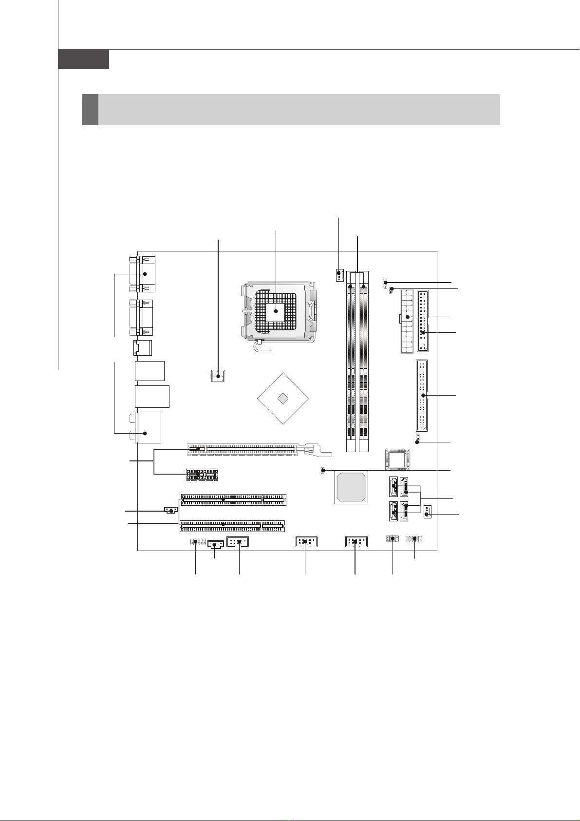
Mainboard Layout ..............................................................................................1-4
Packing Checklist ...............................................................................................1-4
Chapter 2 Hardware Setup ..................................................................................2-1
Quick Components Guide...................................................................................2-2
CPU (Central Processing Unit) ...........................................................................2-2
Introduction to LGA 775 CPU .....................................................................2-3
CPU & Cooler Installation............................................................................2-4
Memory ...............................................................................................................2-6
InstallingDDRII Modules.............................................................................. 2-7
ATX 24-Pin Power Connector: ATX1 .........................................................2-8
ATX 12V Power Connector: JPWR1..........................................................2-8
Power Supply..................................................................................................... 2-8
BackPanel ..........................................................................................................2-8
Connectors.......................................................................................................2-10
Floppy Disk Drive Connector: FDD1 ......................................................... 2-11
Hard Disk Connector: IDE1 ....................................................................... 2-11
Serial ATAII Connectors: SATA1~SATA4 ................................................2-12
SPDIF-OutConnector: SPDOUT1 .............................................................2-12
Fan Power Connectors: CPU_FAN1, SYS_FAN1...................................2-13
IEEE 1394 Connectors: J1394_1 .............................................................2-13
BIOS Password Clear: JPWD1 .................................................................2-14
BIOS Flash Write Protection: JWP1 .........................................................2-14
Front Panel Connectors: JFP1/JFP2 ........................................................2-15
Front Panel Audio Connector: JAUD1 .....................................................2-16
Front USB Connectors: JUSB1, JUSB2 ..................................................2-17
Aux Line-In Connector: JAUX1 ...............................................................2-17
ClearCMOS Jumper:JCMOS1 .................................................................2-18
BIOS Recovery: JBR1 ..............................................................................2-18
Slots ..................................................................................................................2-18
Jumpers ............................................................................................................2-19
PCI (Peripheral Component Interconnect) Express Slots.......................2-19
PCI (Peripheral Component Interconnect) Slots......................................2-19
PCI Interrupt Request Routing ..................................................................2-20

iii
Chapter 3 BIOS Setup ............................................................................................ 3-1
Entering Setup ....................................................................................................3-2
Control Keys ............................................................................................... 3-3
The Main Menu ...................................................................................................3-4
Standard CMOS Features..................................................................................3-6
Advanced BIOS Features..................................................................................3-8
Integrated Peripherals ......................................................................................3-10
Advanced Chipset Features ........................................................................... 3-11
Power Management Setup ..............................................................................3-12
PNP/PCIConfigurations ....................................................................................3-14
H/W Monitor ......................................................................................................3-16
Load Optimized Defaults..................................................................................3-19
BIOS Setting Password ...................................................................................3-19

1-1
Getting Started
Getting Started
Chapter 1
Thank you for choosing the RC410 + SB600 Series
(MS-7275 v1.2) Micro ATX mainboard. The RC410 +
SB600 Series mainboards are based on ATI®RC410 &
SB600 chipsets for optimal system efficiency. Designed
to fit the advanced Intel®Pentium 4 processor, the
mainboards deliver a high performance and profes-
sional desktop platform solution.

MS-7275 Mainboard
1-2
Processor Support*
- Intel®Pentium D 9xx "Presler"Dual Core processor, 800 MHz
Systembus, 65 nm, Only 95W
- Intel®Pentium D 8xx "Smithfield" Dual Core processor, 800 MHz
Systembus, Only 95W
- Intel®P4 HT 6xx "Cedar Mill", 800/533 MHz Systembus, 65 nm
- Intel®P4 HT 6xx "Prescott", 800/533 MHz Systembus
- Intel®Celeron D "Cedar Mill" 533 MHz Systembus
- Intel®Celeron D "Prescott" 533 MHz Systembus
Supported FSB
- 800/ 533 MHz
Chipset
- North Bridge: ATI®RC410
- South Bridge: ATI®SB600
Memory Support**
- DDRII 533/667 SDRAM (2GB Max)
- 2 DDRII DIMMs (240pin / 1.8V)
LAN
- Supports LAN 10/100 Fast Ethermet by RTL8100C
IEEE1394
- Chip integrated by VIA VT 6307
Audio
- Chip integrated by Realtek® ALC888
- Flexible 8-channel audio with jack sensing
- Compliant with Azalia 1.0 Spec
IDE
- 1 port (2 IDE channels).
- Supports Ultra DMA 33/66/100/133 mode
- Supports PIO, Bus Master operation mode
SATAII
- 4 SATAII ports
- Supports 4 SATAII devices.
- Supports storage and data transfers at up to 300 MB/s
Floppy
- 1 floppy port
- Supports 1 FDD with 360K, 720K, 1.2M, 1.44M and 2.88Mbytes
Mainboard Specifications

1-3
Getting Started
Connectors
Backpannel
- 1 serial port (COM1)
- 1 D-Sub VGA port.
- 1 Optical SPDIF jack.
- 1 IEEE 1394 port
- 4 USB 2.0 Ports.
- 1 LAN jack
- 6 flexible audio jacks.
On-Board Pinheaders
- 1 front Audio pinheader
- 1 SPDIF out pinheader
- 1 AUX in pinheader
- 1 IEEE 1394 pinheaders.
- 2 USB 2.0 pinheaders
- 2 front panel pinheaders (JFP1, JFP2)
Slots
- 1 PCI Express x16 slot
- 1 PCI Express x1 slot
- 2 PCI slots.
- Support 3.3V/ 5V PCI bus Interface
Form Factor
- Micro-ATX (24.4cm X 24.4cm)
Mounting
- 8 mounting holes

MS-7275 Mainboard
1-4
MS-7275 v1.2 Micro-ATX Mainboard
Mainboard Layout
PCI1
PCI 2
BATT
+
BIOS
PCIE16X1
JPW1
JAUD1
SPDOUT1
JAUX1
J1394_1
JUSB1 JUSB2
JFP2 JFP1
SATA4
JWP1
SATA2
SATA3SATA1
SYS_FAN1
IDE1FDD1
ATX1
JBR1
CPU_FAN1
DIMM1
DIMM2
JPWD1
JCMOS1
ALC888
VIA
VT6307
RTL8100C
PCIE1X1
COM1
VGA Port
Top: LAN Jack
Bottom: USBports
Top: 1394 port
Bottom: USBports
T:
M:
B:
Line-In
Line-Out
Mic
T:RS-Out
M:CS-Out
B:SS-Out
SPDIFOUT1

2-1
Hardware Setup
Hardware Setup
Chapter 2
This chapter provides you with the information about
hardware setup procedures. While doing the installa-
tion, be careful in holding the components and follow
the installation procedures. For some components, if
you install in the wrong orientation, the components
will not work properly.
Use a grounded wrist strap before handling computer
components. Static electricity may damage the compo-
nents.

MS-7275 Mainboard
2-2
Quick Components Guide
CPU
p,2-3
CPU_FAN1
p,2-13
DDR DIMMs
p,2-7
JBR1
p,2-3
JPWD1
p,2-15
ATX1
p,2-8
FDD1
p,2-11
IDE1
p,2-11
SATA1~4
p,2-12
JCMOS1
p,2-3
SYS_FAN1
p,2-13
JFP1
p,2-16
JFP2
p,2-16
JUSB2
p,2-3
JUSB1
p,2-3
J1394_1
p,2-14
JAUX1
p,2-16
JAUD1
p,2-17
SPDOUT1
p,2-15
PCI Slots
p,2-3
PCI-E Slots
p,2-3
JPW1
p,2-8
Back Panel I/O
p,2-9
JWP1
p,2-14

2-3
Hardware Setup
CPU (Central Processing Unit)
This mainboard supports Intel®Pentium 4 Cedar Mill processor in LGA 775 package.
When you are installing the CPU, make sure to install the cooler to prevent
overheating. If you do not have the CPU cooler, contact your dealer to purchase and
install them before turning on the computer.
For the latest information about CPU, please visit http://www.msi.com.tw/program/
products/mainboard/mbd/pro_mbd_cpu_support.php.
Important
1. Overheating will seriously damage the CPU and system. Always make
sure the cooling fan can work properly to protect the CPU from overheat-
ing.
2. Make sure that you apply an even layer of heat sink paste (or thermal tape)
between the CPU and the heatsink to enhance heat dissipation.
3. While replacing the CPU, always turn off the ATX power supply or unplug
the power supply’s power cord from the grounded outlet first to ensure the
safety of CPU.
Introduction to LGA 775 CPU The surface of LGA 775 CPU.
Remembertoapplysomesilicone
heat transfer compound on it for
better heat dispersion.
Yellow triangle is the Pin 1 indicator
The pin-pad side of LGA 775
CPU.
Yellow triangle is the Pin 1 indicator
Alignment Key Alignment Key

MS-7275 Mainboard
2-4
2. Remove the cap from lever hinge
side (as the arrow shows).
1. The CPU has a plastic cap on it to
protect the contact from damage.
Before you install the CPU, always
cover it to protect the socket pin.
3. The pins of socket reveal.
CPU & Cooler Installation
When you are installing the CPU, make sure the CPU has a cooler at-
tached on the top to prevent overheating. If you do not have the cooler, contact
your dealer to purchase and install them before turning on the computer. Meanwhile,
do not forget to apply some silicon heat transfer compound on CPU before installing
the heat sink/cooler fan for better heat dispersion.
Follow the steps below to install the CPU & cooler correctly. Wrong installation
will cause the damage of your CPU & mainboard.
4. Open the load lever.

2-5
Hardware Setup
Important
1.Confirm if your CPU cooler is firmly installed before turning on your sys-
tem.
2. Do not touch the CPU socket pins to avoid damaging.
3. The availability of the CPU land side cover depends on your CPU packing.
6. After confirming the CPU direction
for correct mating, put down the
CPU in the socket housing frame.
Be sure to grasp on the edge of
the CPU base. Note that the align-
ment keys are matched.
8. Cover theload plate onto the pack-
age.
7. Visually inspect if the CPU is
seated well into the socket. If not,
take out the CPU with pure vertical
motion and reinstall.
alignment
key
5. Lift the load lever up and open the
load plate.

MS-7275 Mainboard
2-6
Important
1.Check the information in PC Health Status of H/W Monitor in BIOS (Chap-
ter 3) for the CPU temperature.
2. Whenever CPU is not installed, always protect your CPU socket pin with the
plastic cap covered (shown in Figure 1) to avoid damaging.
3. Please note that the mating/unmating durability of the CPU is 20 cycles.
Therefore we suggest you do not plug/unplug the CPU too often.
10. Align the holes on the mainboard
with the heatsink. Push down the
cooler until its four clips get
wedged into the holes of the
mainboard.
12.Turn over the mainboard to con-
firm that the clip-ends are cor-
rectly inserted.
11. Press the four hooks down to fas-
ten the cooler. Then rotate the lock-
ing switch (refer to the correct di-
rection marked on it) to lock the
hooks.
9. Press down the load lever lightly
onto the load plate, and then se-
cure the lever with the hook under
retention tab.
locking
switch

2-7
Hardware Setup
Memory
The mainboard provides two 240-pin non-ECC DDRII DIMMs.
For more information on compatible components, please visit http://www.msi.com.tw/
program/products/mainboard/mbd/pro_mbd_trp_list.php.
64x2=128 pin 56x2=112 pin
DDRII
240-pin, 1.8V
Important
- DDRII modules are not interchangeable with DDR and the DDRII standard is
not backwards compatible. You should always install DDRII memory mod-
ules in the DDRII DIMMs and DDR memory modules in the DDR DIMMs.
- To enable successful system boot-up, always insert the memory modules
into the DIMM1 first.
Installing DDRII Modules
1. The memory module has only one notch on the center and will only fit in the right
orientation.
2. Insert the DIMM memory module vertically into the DIMM slot. Then push it in until the
golden finger on the memory module is deeply inserted in the socket.
3. The plastic clip at each side of the DIMM slot will automatically close.
Volt Notch
Important
You can barely see the golden finger if the module is properly inserted in the
socket.

MS-7275 Mainboard
2-8
Power Supply
PIN SIGNAL
13 +3.3V
14 -12V
15 GND
16 PS-ON#
17 GND
18 GND
19 GND
20 Res
21 +5V
22 +5V
23 +5V
24 GND
PIN SIGNAL
1 +3.3V
2 +3.3V
3 GND
4 +5V
5 GND
6 +5V
7 GND
8 PWROK
9 5VSB
10 +12V
11 +12V
12 NC
ATX1 Pin Definition
PIN SIGNAL
1 GND
2 GND
3 12V
4 12V
JPWR1 Pin Definition
pin 12
pin 13
JPWR1
Important
1. Maker sure that all the connectors are connected to proper ATX power sup-
plies to ensure stable operation of the mainboard.
2. Power supply of 350 watts (and above) is highly recommended for system
stability.
3. ATX 12V power connection should be greater than 18A.
ATX 24-Pin Power Connector: ATX1
This connector allows you to connect an ATX 24-pin power supply.
To connect the ATX 24-pin power supply, make sure the plug of the
power supply is inserted in the proper orientation and the pins are
aligned. Then push down the power supply firmly into the connec-
tor.
You may use the 20-pin ATX power supply as you like. If you’d like
to use the 20-pin ATX power supply, please plug your power sup-
ply along with pin 1 & pin 13 (refer to the image at the right hand).
There is also a foolproof design on pin 11, 12, 23 & 24 to avoid
wrong installation.
ATX 12V Power Connector: JPWR1
This 12V power connector is used to provide power to the CPU.
1
ATX1
12
24
13
3
42
1

2-9
Hardware Setup
Back Panel
USB Ports
1394 Port LAN
VGA Port
Serial Port
Serial Port Connector
The serial port is a 16550A high speed communications port that sends/ receives 16
bytes FIFOs. You can attach a serial mouse or other serial devices directly to the
connector.
VGA Connector
The DB15-pin female connector is provided for VGA monitors.
Optical S/PDIF-Out connector
This SPDIF (Sony & Philips Digital Interconnect Format) connector is provided for
digital audio transmission to external speakers through an optical cable.
IEEE 1394 Port
The 1394 port on the back panel provides connection to 1394 devices.
USB Connectors
The OHCI (Open Host Controller Interface) Universal Serial Bus root is for attaching
USB devices such as keyboard, mouse, or other USB-compatible devices.
LAN (RJ-45) Jack
The standard RJ-45 jack is for connection to single Local Area Network (LAN). You
can connect a network cable to it.
L-In
CS-Out
RS-Out
L-Out
Mic
SPDIF Out SS-Out
LinkIndicatorActivityIndicator
LED Color LED State Condition
Off LAN link isnot established.
Left Orange On(steadystate) LANlinkis established.
On (brighter & pulsing)The computeriscommunicating with anothercomputeron the LAN.
Green Off 10 Mbit/secdata rateis selected.
Right On 100Mbit/sec datarate is selected.
Orange On 1000Mbit/sec datarate is selected.

MS-7275 Mainboard
2-10
Audio Port Connectors
These audio connectors are used for audio devices. You can differentiate the color
of the audio jacks for different audio sound effects.
Blue audio jack - Line In
Green audio jack - Line Out, is a connector for speakers or headphones.
Pink audio jack - Mic In, is a connector for microphones.
Black audio jack - Rear-Surround Out in 5.1 / 7.1 channel mode.
Orange audio jack - Center/ Subwoofer Out in 5.1/ 7.1 channel mode.
Gray audio jack - Side-Surround Out in 7.1 channel mode.

2-11
Hardware Setup
Connectors
Floppy Disk Drive Connector: FDD1
This standard FDD connector supports 360K, 720K, 1.2M, 1.44M and 2.88M floppy
disk types.
FDD1
IDE1 (Primary IDE Connector)
IDE1 can connect a Master and a Slave drive. You must configure the second
hard drive to Slave mode by setting the jumper accordingly.
Hard Disk Connector: IDE1
The mainboard provides a one-channel Ultra ATA 100 bus Master IDE controller that
supports PIO mode 0~4, Bus Master, and Ultra DMA 33/66/100 function. You can
connect hard disk drives, CD-ROM drives and other IDE devices.
IDE1
IDE VDMA Controller RAID ATAPI
1 33/66/100/133 SouthBridge N/A Yes
IDE1 Definition
Important
If you install two hard disks on cable, you must configure the second drive to
Slave mode by setting its jumper. Refer to the hard disk documentation
supplied by hard disk vendors for jumper setting instructions.

MS-7275 Mainboard
2-12
PIN SIGNAL PIN SIGNAL
1 GND 2 TXP
3 TXN 4 GND
5 RXN 6 RXP
7 GND
SATA1~ SATA4 Pin Definition
SerialATAII Connectors: SATA1~SATA4
SATA1~SATA4 are high-speed Serial ATA interface ports. Each supports 2nd genera-
tion serial ATA data rates of 300MB/s and is fully compliant with Serial ATA 2.0
specifications. Each Serial ATA connector can connect to 1 hard disk device.
1
7
SATA1SATA2
SATA3SATA4
1
7
Important
Please do not fold the Serial ATA cable into 90-degree angle. Otherwise,
data loss may occur during transmission.
SPDIF-Out Connector: SPDOUT1
This connector is used to connect SPDIF (Sony & Philips Digital Interconnect Format)
interface for digital audio transmission.
SPDOUT1
VCC
SPDIF
GND

2-13
Hardware Setup
Fan Power Connectors: CPU_FAN1, SYS_FAN1
The fan power connectors support system cooling fan with +12V. When connecting
the wire to the connectors, always take note that the red wire is the positive and
should be connected to the +12V, the black wire is Ground and should be connected
to GND. If the mainboard has a System Hardware Monitor chipset on-board, you must
use a specially designed fan with speed sensor to take advantage of the CPU fan
control.
CPU_FAN1
SENSOR
+12V
GND
CONTROL
Important
1. Please refer to the recommended CPU fans at Intel® official website or
consult the vendors for proper CPU cooling fan.
2. CPUFAN1 supports fan control. You can install Core Center utility (refer to
Appendix for details) that will automatically control the CPU fan speed
according to the actual CPU temperature.
SYS_FAN1
SENSOR
+12V
GND
CONTROL
IEEE1394 Connectors:J1394_1
The mainboard provides IEEE1394 pinheaders that allow you to connect IEEE 1394
ports via an external IEEE1394 bracket (optional).
Pin Definition
PIN SIGNAL PIN SIGNAL
1TPA+ 2 TPA-
3 Ground 4 Ground
5 TPB+ 6 TPB-
7 Cablepower 8 Cablepower
9 Key(nopin) 10 Ground
J1394_1
19
210
Table of contents
Other MSI Motherboard manuals

MSI
MSI G31M3 Series Instructions for use

MSI
MSI MS-5191 User manual

MSI
MSI B360M BAZOOKA User manual

MSI
MSI P6NG Neo Series User manual

MSI
MSI 845GEM Series User manual

MSI
MSI MS-6566E User manual

MSI
MSI PRO A620M-E User manual

MSI
MSI MS-7758 (v1.x) User manual

MSI
MSI MAG X570S TOMAHAWK MAX WIFI User manual

MSI
MSI Wind Board D410 Series User manual