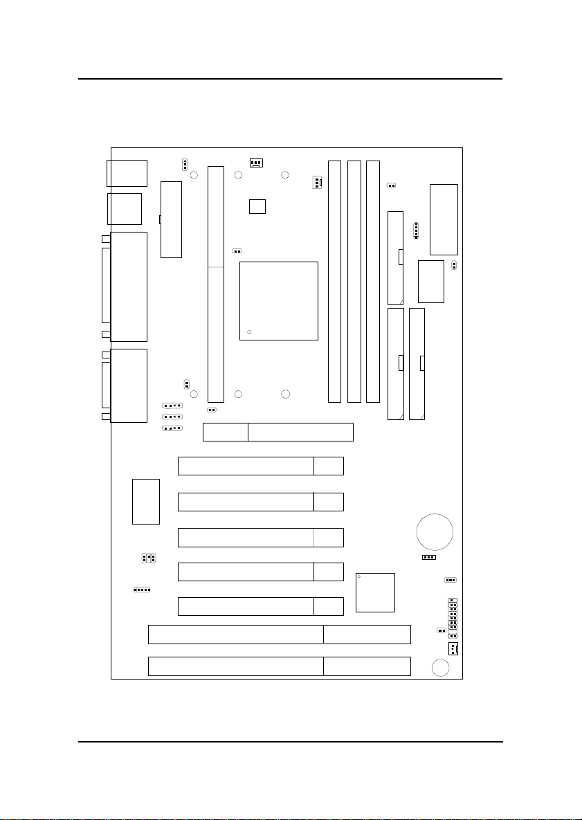
MSI MS-6163VA User manual
Other MSI Motherboard manuals

MSI
MSI PRO H610M-C EX User manual
 User manual")
MSI
MSI Z68MA-ED55 (B3) User manual

MSI
MSI MS-7388 User manual

MSI
MSI 970 User manual

MSI
MSI MS-6339 User manual

MSI
MSI FM2-A85XMA-P33 series User manual

MSI
MSI 865PE Neo3-F User manual

MSI
MSI X299 GAMING M7 ACK User manual

MSI
MSI 790XT-G45 series User manual

MSI
MSI MPG B550 GAMING PLUS User manual

MSI
MSI PRO B760-P DDR4 II User manual

MSI
MSI G31M Series User manual

MSI
MSI X670E GAMING PLUS WIFI User manual

MSI
MSI IM-GM45 User manual

MSI
MSI K7T TURBO2 - K7T Turbo 2 Motherboard User manual

MSI
MSI E350DM-E33 series User manual

MSI
MSI PRO H610M-E User manual

MSI
MSI 655 Max User manual

MSI
MSI IFC-815N2D Series User manual

MSI
MSI MS-6309 Manual