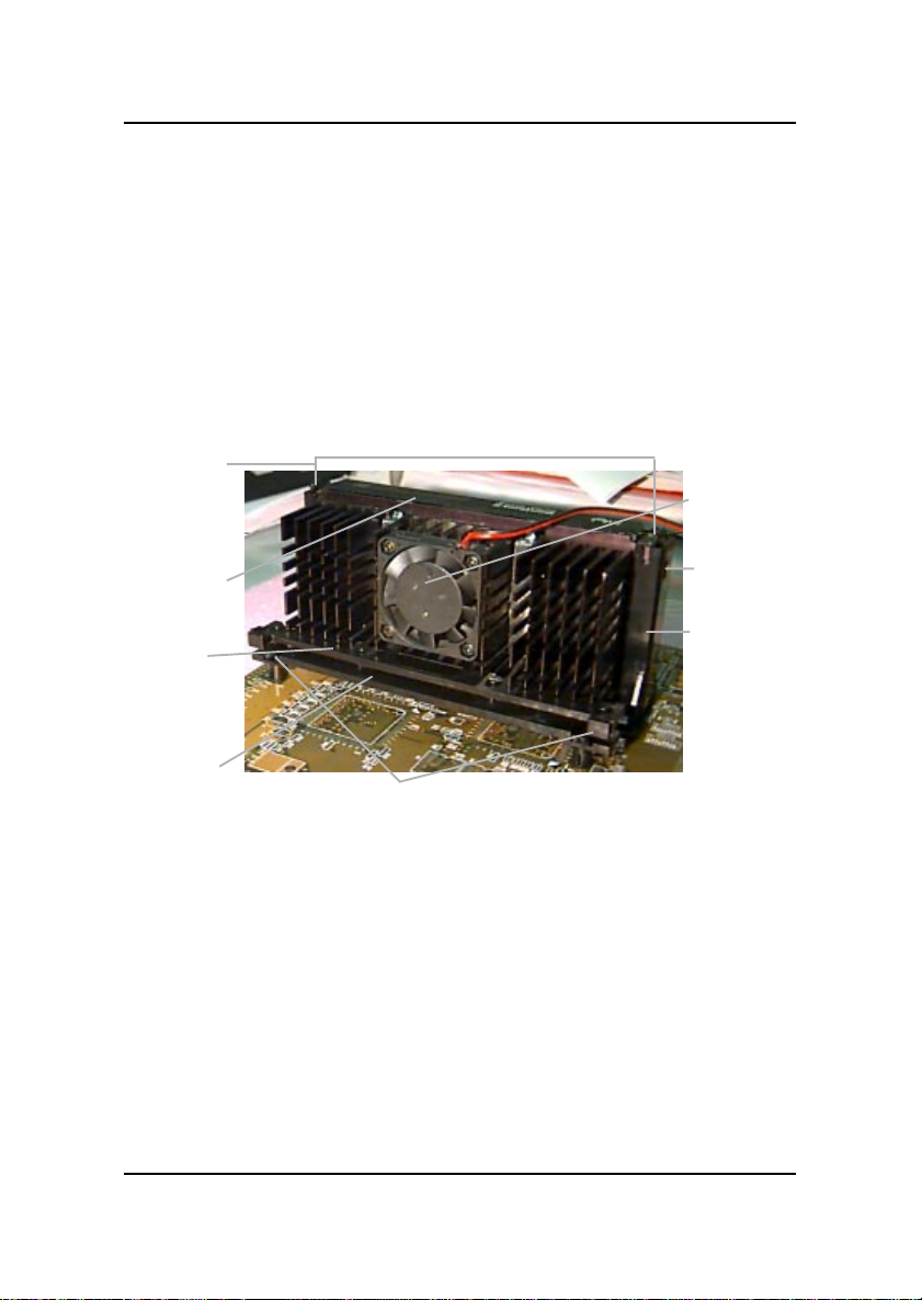
MSI MS-6151 User manual

MS-6151

CHAPTER 1CHAPTER 1
CHAPTER 1CHAPTER 1
CHAPTER 1 INTRODUCTIONINTRODUCTION
INTRODUCTIONINTRODUCTION
INTRODUCTION
1-1
The ATX BX9 mainboard is a high-performance personal computer
mainboard based on the Intel®Pentium®II processor. This mainboard
combinesleadingedgeAGPATI®3D Rage PRO Turbo/Rage 128VR (re-
served) technology in graphics and Creative®ES1371/ES1373 (reserved) PCI
technology in audio. The Intel®Pentium®II processor supports MMXTM
(Multimedia Extension) technology.
The mainboard uses the highly integrated Intel®82443BX AGP chipset to
support the PCI/ISA and Green standards, and to provide the Host/AGP
bridge. The Intel®82371EB chipset integrates all system control functions
such as ACPI (Advanced Configuration and Power Interface). The ACPI
provides more Energy Saving Features for the OSPM(OS Direct Power
Management) function. The Intel®82371EB chipset also improves the IDE
transfer rate by supporting Ultra DMA/33 IDE that transfers data at the rate
of33MB/s.
The mainboard also supports the System Hardware Monitor Controller as an
optional function. Its functions include: CPU /power supply/chassis fan
revolution detect, CPU/system voltage monitor, system temperature monitor,
and chassis intrusion detect(optional).
Chapter 1
INTRODUCTION

CHAPTER 1CHAPTER 1
CHAPTER 1CHAPTER 1
CHAPTER 1 INTRODUCTIONINTRODUCTION
INTRODUCTIONINTRODUCTION
INTRODUCTION
1-2
1.1 Mainboard Features
Processor
lSlot 1 for Intel®Pentium®II/CeleronTM processor.
lSupports233MHz,266MHz,300MHz,333MHz,350MHz,400MHz,
450MHz,andfaster.
Chipset
lIntel®82443BX/PIIX4Echipset.
ClockGenerator
l66 and 100MHz clocks are supported.
MainMemory
lSupports six memory banks using three 168-pin unbuffered DIMM.
lSupportsa maximum memorysizeof 384MB(8Mx 8) or768MB(16M x4)
registered DIMM only.
lSupportsECC(1-bitErrorCodeCorrect)function.
lSupports 3.3v SDRAM DIMM.
Slots
lOne AGP (Accelerated Graphics Port) slot.
- AGP specification compliant
- AGP 66/133MHz 3.3v device support
lFour 32-bit Master PCI Bus slots and two 16-bit ISA bus slots.
lSupports 3.3v/5v PCI bus Interface.
On-BoardIDE
lAn IDE controller on the Intel®PIIX4E PCI Chipset provides IDE HDD/
CD-ROM with PIO, Bus Master and Ultra DMA/33 operation modes.
lCan connect up to four IDE devices.

CHAPTER 1CHAPTER 1
CHAPTER 1CHAPTER 1
CHAPTER 1 INTRODUCTIONINTRODUCTION
INTRODUCTIONINTRODUCTION
INTRODUCTION
1-3
On-BoardPeripherals
lOn-Board Peripherals include:
- 1 floppy port supports 2 FDD with 360K, 720K, 1.2M, 1.44M and
2.88Mbytes.
- 1 serial port (COM A) + 1 serial connector (COM B)
- 1 parallel port supports SPP/EPP/ECP mode
- 2 USB ports
-1IrDAconnectorforSIR/FIR.
-1VGA port
- 1 audio port (Line_In, Line_Out, and Mic_In jack) and 1 MIDI/Game
port
VGA
lATI®3DRAGE PRO TURBO/128VR(reserved)
-RunningonAGPBUS.
-Onboard8MBSDRAM.
-3DAcceleration.
- AGP 2x mode (133MHz) support pipelined and sideband protocols.
Note: Installing AGP graphics card into the AGP slot, will automatically
disable the onboard VGA.
Sound
lCreative®ES1371/ES1373(reserved)
-RunningonPCIBUS.
-64Voice andAC3Capable(ES1373 only)
- Support Direct Sound and Direct Sound 3D
-AC97’ Compliant
I/OChip
lWinbond®multi super I/O W83977EF
- 2M bps fast tape drive, IRQ sharing
- Device Power Management
- 8042-based keyboard controller (support PS/2 mouse)

CHAPTER 1CHAPTER 1
CHAPTER 1CHAPTER 1
CHAPTER 1 INTRODUCTIONINTRODUCTION
INTRODUCTIONINTRODUCTION
INTRODUCTION
1-4
BIOS
lThe mainboard BIOS provides “Plug & Play” BIOS which detects the
peripheral devices and expansion cards of the board automatically.
lThe mainboard provides a Desktop Management Interface(DMI) function
which records your mainboard specifications.
lACPI(Advanced Configuration and Power Interface) feature.
Dimension
lATX FormFactor: 30cm(L) x 19.2cm(W) x 4layersPCB
Mounting
l6 mounting holes.
SystemHardwareMonitor(optional)
lCPU/Power Supply/Chassis Fan Revolution Detect
lCPU Fan Control (the fan will automatically stop when the system enters
suspend mode)
lSystem Voltage Detect
lCPU Overheat Warning.
lDisplay Actual Current Voltage
OtherFeatures
lKeyboard Password Wake-Up (reserved)
lLAN Wake-Up
lInternal/External Modem Wake-Up

CHAPTER 1CHAPTER 1
CHAPTER 1CHAPTER 1
CHAPTER 1 INTRODUCTIONINTRODUCTION
INTRODUCTIONINTRODUCTION
INTRODUCTION
1-5
1.2 Mainboard Layout
MS-6151 ATX BX9 Mainboard
PCI SLOT 3
PCI SLOT 2
PCI SLOT 1
ISA SLOT 1
ATX
Power Supply
FW82443BX
SLOT 1
DIMM 2
Top: mouse
Bottom:
keyboard
Top:Port1
USB
DIMM 1
IDE2
Bottom:
Port2
IDE1
FDD
ATI3D
RAGEPRO
FW82371EB
JMDM1
Creative
ES1371
SYSFAN
JFP1
JGS1
JGL1
JBAT1
JWOL1
BIOS
J4: MDM_IN
J5: AUX_IN
COM 2
CPUFAN
JSOR1
JRMS1
SW1
PSFAN
IR
BATT
+
Top: LPT
Bottom:
COMA
VGAPort
Top: Midi/
GamePort
Bottom:
Line-Out
Line-In
Mic
1
4
J6: CD_IN
J2
SDRAM
SDRAM
JVSB1
(Reserved)
System
Hardware
Monitor
(optional)
SDRAM
SDRAM
DIMM 3
SW2
PCI SLOT 4
ISA SLOT 2
AGP SLOT
Buzzer

CHAPTER 2CHAPTER 2
CHAPTER 2CHAPTER 2
CHAPTER 2 HARDHARD
HARDHARD
HARDWW
WW
WARE INSTARE INST
ARE INSTARE INST
ARE INSTALLAALLA
ALLAALLA
ALLATIONTION
TIONTION
TION
2-1
Chapter 2
HARDWARE INSTALLATION
2.1 Central Processing Unit: CPU
The mainboard operates with Intel®Pentium®II/CeleronTM processor. The
mainboard uses a CPU Slot called Slot 1 for easy CPU installation and a
jumper switch (SW1) to set the proper speed for the CPU. The CPU should
always have a Heat Sink and a cooling fan attached to prevent overheating.

CHAPTER 2CHAPTER 2
CHAPTER 2CHAPTER 2
CHAPTER 2 HARDHARD
HARDHARD
HARDWW
WW
WARE INSTARE INST
ARE INSTARE INST
ARE INSTALLAALLA
ALLAALLA
ALLATIONTION
TIONTION
TION
2-2
2.1-1 CPU Installation Procedures
A. OEM Pentium®II Processor Installation Procedures
Different kinds of Pentium®II processor that is currently used: the OEM
version, the Boxed version, and CeleronTM. OEM Pentium®II Processor has
no Heat Sink, Fan and Heat Sink Support, the Boxed Pentium®II Processor
is provided with Heat Sink w/ fan and Heat Sink Support, while the
CeleronTM processor is a plain processor card without cover or heatsink..
Required Things:
Pentium®IIprocessor-Processor.
*RetentionMechanism(RM)- Plastic Guide that holds the S.E.C.Catridge
in the Slot 1 connector.
*RetentionMechanism AttachMount(RMAM)-Bolt/Bridge assemblies
inserted up through the bottom of the
motherboard. RM secures to RMAM ( 2
RMAM required per RM ).
*Heat Sink SupportBase (HSSBASE) - Plastic support bar mounted to
the mainboard under the ATX heatsink.
(One leg is always bigger than the other one)
Processor
Lock
Retention
Mechanism
Pentium®II
Processor
Heat Sink
W/Fan
Notch Hole
Heat Sink
Support Base Heat Sink
Support Pin
Heat Sink
Support
Top Bar

CHAPTER 2CHAPTER 2
CHAPTER 2CHAPTER 2
CHAPTER 2 HARDHARD
HARDHARD
HARDWW
WW
WARE INSTARE INST
ARE INSTARE INST
ARE INSTALLAALLA
ALLAALLA
ALLATIONTION
TIONTION
TION
2-3
*HeatSink Support Pin (HSSPIN)- Plastic pins inserted through the
HSSBASE to secure it to the mainboard (2
required per Assembly).
*Heat Sink Support Top Bar (HSSTOP) - Plastic bar that clips onto the
HSSBASE through the fins on the ATX
heatsink.
**Heat Sink w/ fan - Heat Sink that can be attached to the Pentium®II
processorwithmetalclip.
Note:* Provided by MSI mainboard.
** Provided by Special request.
RM
HSSPIN
HSSTOP
HSSBASE
RMAM

CHAPTER 2CHAPTER 2
CHAPTER 2CHAPTER 2
CHAPTER 2 HARDHARD
HARDHARD
HARDWW
WW
WARE INSTARE INST
ARE INSTARE INST
ARE INSTALLAALLA
ALLAALLA
ALLATIONTION
TIONTION
TION
2-4
SLOT1
Retention
Mechanism
êê
Key
êê
Retention
Mechanism
Attach Mount
Notch
Key
Step 1: Insert the Retention Mechanism Attach Mount at the bottom
of the mainboard.
Step 2: Install the Retention Mechanism.
Look for the key on Slot 1, and match it with the Notch Key on the
Retention Mechanism for proper direction. Then, attach the
Retention Mechanism to the Retention Mechanism Attach Mount.
Use a Screwdriver to secure the Retention Mechanism.

CHAPTER 2CHAPTER 2
CHAPTER 2CHAPTER 2
CHAPTER 2 HARDHARD
HARDHARD
HARDWW
WW
WARE INSTARE INST
ARE INSTARE INST
ARE INSTALLAALLA
ALLAALLA
ALLATIONTION
TIONTION
TION
2-5
Step 3: Install the Heat Sink Support Base.
Look for the Two holes across Slot 1, and match it with the Two legs
of the Heat Sink Support Base for the proper direction. Take note
that one hole/leg is bigger than the other. The Four top pins of the
Heat Sink Support Base should also be oriented towards Slot 1.
Push the Heat Sink Support Base onto the mainboard, until you hear
a click sound. Check for a perfect fit.
Step 4: Install the Heat Sink Support Pin.
Push the Heat Sink Support Pins onto the two holes of the Heat Sink
Support Base. Check for a perfect fit. These pins are used to secure
the Heat Sink Support Base.
Heat Sink
Support Base
Heat Sink
Support Pin
Leg
pins

CHAPTER 2CHAPTER 2
CHAPTER 2CHAPTER 2
CHAPTER 2 HARDHARD
HARDHARD
HARDWW
WW
WARE INSTARE INST
ARE INSTARE INST
ARE INSTALLAALLA
ALLAALLA
ALLATIONTION
TIONTION
TION
2-6
S.E.C. Cartridge - Thermal
P
Isometric View
Step 5: Install the Heat Sink with Fan to the Processor.
Push down the metal clips, so that they are in line with the back of
the Heat Sink. Be careful, so as not detach the metal clips from the
HeatSink.
In case the metal clips are detached from the Heat Sink, re-attach
them. Look for the arrow on the metal clip. This arrow should be
pointing down and aligned with the Heat Sink Support Base Holder.
Attach the Heat Sink to the processor.
- Look at the back of the Heat Sink and take note of the 2 secure
posts. Insert these 2 Secure posts to the 2 secure holes on the
back of the processor.
- Align the ears of the metal clips with the clip holders on the back of
the processor. Use a screw driver to push the metal clips onto the
clip holders. Check for a perfect fit.
Pentium®II Processor (Back)
â
Thearrow
shouldbe
pointing
down.
Metal Clips
Heat Sink w/ Fan
Metal Clips Ear
Metal Clips Ear
Secure
Posts
Heat Sink w/ Fan(Back)
HeatSink
BaseHolder
Secure
holes
Clip Holder
Clip Holder

CHAPTER 2CHAPTER 2
CHAPTER 2CHAPTER 2
CHAPTER 2 HARDHARD
HARDHARD
HARDWW
WW
WARE INSTARE INST
ARE INSTARE INST
ARE INSTALLAALLA
ALLAALLA
ALLATIONTION
TIONTION
TION
2-7
Step 6: Install the Processor.
Unlock the Processor by pushing in the Processor Locks.
Insert the Processor like inserting a PCI or an ISA card.
Step 7: Lock the Processor Locks.
Secure the CPU by pulling the Processor Locks out.
èç
çè

CHAPTER 2CHAPTER 2
CHAPTER 2CHAPTER 2
CHAPTER 2 HARDHARD
HARDHARD
HARDWW
WW
WARE INSTARE INST
ARE INSTARE INST
ARE INSTALLAALLA
ALLAALLA
ALLATIONTION
TIONTION
TION
2-8
Step 8: Install the Heat Sink Support Top Bar.
Push the Heat Sink Support Top Bar to the Heat Sink Support Base,
Until you hear a “click” sound. Check for a perfect fit.
The installation is now complete.
Heatsink
Support Top
Bar

CHAPTER 2CHAPTER 2
CHAPTER 2CHAPTER 2
CHAPTER 2 HARDHARD
HARDHARD
HARDWW
WW
WARE INSTARE INST
ARE INSTARE INST
ARE INSTALLAALLA
ALLAALLA
ALLATIONTION
TIONTION
TION
2-9
B. Boxed Pentium®II Processor Installation Procedures
The Boxed Pentium®II Processor has a built- in Fan and Heat Sink. It also
has a Heat Sink Support. So if you’re going to use a Boxed PentiumTM II
Processor, all you need is the Retention Mechanism.
SLOT1
Retention
Mechanism
êê
Key
êê
Retention
Mechanism
Attach Mount
Notch
Key
Step 1: Insert the Retention Mechanism Attach Mount at the bottom
of the mainboard.
Step 2: Install the Retention Mechanism.
Look for the key on Slot 1, and match it with the Notch Key on the
Retention Mechanism for proper direction. Then, attach the
Retention Mechanism to the Retention Mechanism Attach Mount.
Use a Screwdriver to secure the Retention Mechanism.

CHAPTER 2CHAPTER 2
CHAPTER 2CHAPTER 2
CHAPTER 2 HARDHARD
HARDHARD
HARDWW
WW
WARE INSTARE INST
ARE INSTARE INST
ARE INSTALLAALLA
ALLAALLA
ALLATIONTION
TIONTION
TION
2-10
Step 3: Install the Heat Sink Support Base.
Look for the 2 holes across Slot 1, and match it with the 2 Heat Sink
Support Base. Take note that one hole/base is bigger than the other.
Push the Heat Sink Support Base onto the mainboard, until you hear
a click sound. Check for a perfect fit.
PC-3742
Retention
Mechanism
Notch
Hole
HeatSink
Support Base

CHAPTER 2CHAPTER 2
CHAPTER 2CHAPTER 2
CHAPTER 2 HARDHARD
HARDHARD
HARDWW
WW
WARE INSTARE INST
ARE INSTARE INST
ARE INSTALLAALLA
ALLAALLA
ALLATIONTION
TIONTION
TION
2-11
PC-3743
HeatSink
Support Lock
Intel®Boxed
Pentium®II
Processor
Step 4: Install the Heat Sink Support.
Attach the 2 Heat Sink Supports to the sides of the Processor. These
Heat Sink Supports will fit in any direction, so be sure that the Heat
Sink Support Locks are oriented outwards for the proper direction.
HeatSink
Support

CHAPTER 2CHAPTER 2
CHAPTER 2CHAPTER 2
CHAPTER 2 HARDHARD
HARDHARD
HARDWW
WW
WARE INSTARE INST
ARE INSTARE INST
ARE INSTALLAALLA
ALLAALLA
ALLATIONTION
TIONTION
TION
2-12
PC-3744
Processor
Lock
Heatsink
Support
Lock
Step 5: Unlock the Processor Locks and Heat Sink Support Locks.
Push in the Processor Locks. Open the Heat Sink Support Locks.
Step 6: Insert the Processor like inserting a PCI or an ISA card.

CHAPTER 2CHAPTER 2
CHAPTER 2CHAPTER 2
CHAPTER 2 HARDHARD
HARDHARD
HARDWW
WW
WARE INSTARE INST
ARE INSTARE INST
ARE INSTALLAALLA
ALLAALLA
ALLATIONTION
TIONTION
TION
2-13
PC-3745
Step 7: Lock the Processor Locks and Heat Sink Support Locks
Secure the CPU by pushing out the Processor Locks. Close the Heat
Sink Support Locks.
The installation is now complete.

CHAPTER 2CHAPTER 2
CHAPTER 2CHAPTER 2
CHAPTER 2 HARDHARD
HARDHARD
HARDWW
WW
WARE INSTARE INST
ARE INSTARE INST
ARE INSTALLAALLA
ALLAALLA
ALLATIONTION
TIONTION
TION
2-14
SLOT1
Retention
Mechanism
êê
Key
êê
Retention
Mechanism
Attach Mount
Notch
Key
Step 1: Insert the Retention Mechanism Attach Mount at the bottom
of the mainboard.
Step 2: Install the Retention Mechanism.
Look for the key on Slot 1, and match it with the Notch Key on the
Retention Mechanism for proper direction. Then, attach the
Retention Mechanism to the Retention Mechanism Attach Mount.
Use a Screwdriver to secure the Retention Mechanism.
C. OEM CeleronTM Processor Installation Procedures
This manual suits for next models
1
Table of contents
Other MSI Motherboard manuals

MSI
MSI X399 GAMING PRO CARBON AC User manual

MSI
MSI B450M-A PRO MAX User manual

MSI
MSI K7N415 Pro User manual

MSI
MSI Z270I GAMING PRO CARBON AC User manual

MSI
MSI MS-6187 User manual

MSI
MSI B150M NIGHT ELF User manual

MSI
MSI Z97S SLI PLUS User manual

MSI
MSI 845PE-V2 Series User manual

MSI
MSI MS-7502 Series User manual

MSI
MSI MS-7236 User manual

MSI
MSI J-TX98 R2 User manual

MSI
MSI MS-7242 Instructions for use

MSI
MSI Z390-S01 User manual

MSI
MSI P35 Neo Combo Series User manual

MSI
MSI MPG B550 GAMING CARBON WIFI User manual

MSI
MSI B360M MORTAR User manual

MSI
MSI Z87-G43 GAMING User manual

MSI
MSI MS-7530 User manual

MSI
MSI A88X-G45 GAMING User manual

MSI
MSI AmethystM User manual