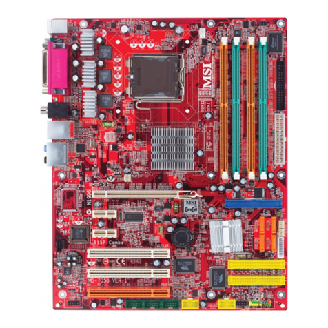
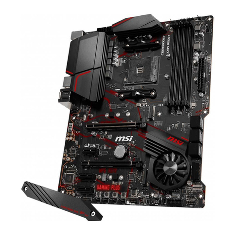
MSI MS-6119 ATX BX2 Installation instructions

MS-6119 ATX BX2 Mainboard
MICRO-STAR INTERNATIONAL COMPANY LTD.
Specification & User’s Guide
MS-6119 ATX BX2 Mainboard
Specification & User’s Guide
1. Introduction
The MSI ATX BX2 mainboard is a high-performance personal computer mainboard
based on the Pentium®II processor. The Pentium®II processor supports MMXTM(Multime-
dia Extension) technology.
The mainboard uses the highly integrated Intel®82443BX AGP chipset to support
the PCI/ISA and Green standards, and to provide the Host/AGP bridge. The Intel®
82371AB chipset integrates all system control functions such as ACPI (Advanced Configu-
ration and Power Interface). The ACPI provides more Energy Saving Features for the
OSPM(OS Direct Power Management) function. The Intel®82371EB chipset also improves
the IDE transfer rate by supporting Ultra DMA/33 IDE that transfers data at the rate of
33MB/s.
The mainboard also supports the LM78 System Hardware Monitor Controller as an
optional function. The LM78 function includes: CPU /power supply/chassis fan revolution
detect, CPU/system voltage monitor, system temperature monitor, and chassis intrusion
detect(optional).
MICRO-STAR
INTERNATIONAL
COMPANY LTD.
MICRO-STAR
INTERNATIONAL
COMPANY LTD.
Specification & User’s Guide
1

MS-6119 ATX BX2 Mainboard
MICRO-STAR INTERNATIONAL COMPANY LTD.
Specification & User’s Guide
2
Table of Contents
1. Introduction.............................................................................................................................1
2.MainboardSpecification...........................................................................................................3
3. Mainboard Layout..................................................................................................................6
4. Backpanel Layout.................................................................................................................7
4.1 Connectors................................................................................................................7
4.1-1 Mouse Connector......................................................................................7
4.1-2 Keyboard Connector.................................................................................8
4.1-3USBConnectors..........................................................................................8
4.1-4 Parallel Port Connector.............................................................................9
4.1-5 Serial Port Connectors..............................................................................10
5. Slot 1....................................................................................................................................11
6. DIMM DRAM Addressing..................................................................................................15
7, CPU Fan Power Connector..................................................................................................16
8. Irda Infrared Module Connector......................................................................................... 16
Appendixes

MS-6119 ATX BX2 Mainboard
MICRO-STAR INTERNATIONAL COMPANY LTD.
Specification & User’s Guide
2. Mainboard Specification
lSlot 1 for Pentium®II Processor .
lSupports 200MHz, 233MHz, 266MHz, 300MHz,
333MHz, and faster.
lCore/Bus ratios are x2, x2.5, x3, x3.5, x4, x4.5,
x5, x5.5, x6 and higher.
CPU
lOn-board switching mode DC-DC Step Down
Regulator.
lConforms to Intel®VRM ver 8.2 specifications.
lOver-Voltage and Over-Current protection.
Switching Voltage
Regulator
lIntel®82443BX AGP chipset.
Chipset
l66.6MHz and 100MHz clocks are supported.
(75 MHz and 83MHz reserved)
Clock Generator
lSupports eight memory banks using three 168-
pin unbuffered DIMM sockets.
lSupports a maximum memory size of 384MB
(8M x 8) or 768MB(16M x 4) registered DIMM
only.
lSupports ECC(1-bit Error Code Correct) and
EC(Multiple-Bit Error Checking) function.
lSupports 3.3v SDRAM DIMM.
Main Memory
lOne AGP(Accelerated Graphics Port) slot.
- AGP specification compliant
- AGP 66/133MHz 3.3v device support
lFour 32-bit Master PCI Bus slots and three 16-bit
ISA bus slots wherein one shared slot can be used
as ISA or PCI.
lSupports 3.3v/5v PCI bus Interface.
Slots
lAn IDE controller on the Intel®82371EB PCI
Chipset provides IDE HDD/CD-ROM with PIO,
Bus Master and Ultra DMA/33 operation modes.
lCan connect up to four IDE devices.
On-Board IDE
FEATURES SPECIFICATIONS
3

MS-6119 ATX BX2 Mainboard
MICRO-STAR INTERNATIONAL COMPANY LTD.
Specification & User’s Guide
FEATURES SPECIFICATIONS
lOn-Board Peripherals include:
- 1 floppy port supports 2 FDD with 360K,
720K, 1.2M, 1.44M and 2.88Mbytes.
- 2 serial ports (COMA + COMB)
- 1 parallel port supports SPP/EPP/ECP
mode
- 2 USB ports
- 1 IrDA connector for Fast IrDA(reserved).
On-Board Peripherals
lThe mainboard BIOS provides “Plug & Play”
BIOS which detects the peripheral devices and
expansion cards of the board automatically.
lThe mainboard provides a Desktop Management
Interface(DMI) function which records your
mainboard specifications.
BIOS
lCPU/Power Supply/Chassis Fan Revolution
Detect
lCPU Fan Control (the fan will automatically
stop when the system enters suspend mode)
lSystem Voltage Detect
lCPU Overheat Warning (reserved)
lChassis Intrusion Detect(reserved)
lDisplay Actual Current Voltage
On-Board System
Hardware
Monitor(LM78)
lPIIX4(82371EB) built-in RTC.
RTC
Keyboard Connector lPS/2®keyboard interface and PS/2®mouse interface.
Mounting
lATX Form Factor: 30cm(L) x 18.6cm(W) x 4
layers PCB.
lDouble deck PS/2®keyboard & PS/2®mouse.
lDouble deck USB port.
lDouble deck Serial & LPT port.
lDouble deck I/O connectors, compatible with
Intel®Venus Mainboard.
l6 mounting holes.
Dimension
4

MS-6119 ATX BX2 Mainboard
MICRO-STAR INTERNATIONAL COMPANY LTD.
Specification & User’s Guide
FEATURES SPECIFICATIONS
lKeyboard Password Wake-Up
lLAN Wake-Up
lInternal/External Modem Wake-Up
Other features
5

MS-6119 ATX BX2 Mainboard
MICRO-STAR INTERNATIONAL COMPANY LTD.
Specification & User’s Guide
DIMM 1
Top: mouse
Bottom:
keyboard
Top: Port 1
USB
Top: LPT
Bottom:
COM A
COM B
DIMM 2
DIMM 3
ISA SLOT
ISA SLOT
PCI SLOT 4
PCI SLOT 3
PCI SLOT 2
PCI SLOT 1
SLOT 1
ISA SLOT
FDC
BATT
+
IDE2
IDE1
LM75
(optional)
ATX
Power Supply
BIOS
FW82371EB
FW82443BX
Clock
Generator AGP
Bottom:
Port 2
3. Mainboard Layout
6
JMDM1
DIMM Clock
buffers

MS-6119 ATX BX2 Mainboard
MICRO-STAR INTERNATIONAL COMPANY LTD.
Specification & User’s Guide
7
4. Backpanel Layout
Mouse
Keyboard USB
Parallel
COM A COM B
4.1-1 Mouse Connector
4.1 Connectors
PS/2 Mouse (6-pin Female)
21
3
4
5
PIN SIGNAL DESCRIPTION
1 Mouse DATA Mouse DATA
2 NC No connection
3 GND Ground
4VCC +5V
5 Mouse Clock Mouse clock
6 NC No connection
6
PS/2 Mouse Pin Definition

MS-6119 ATX BX2 Mainboard
MICRO-STAR INTERNATIONAL COMPANY LTD.
Specification & User’s Guide
8
4.1-2 Keyboard Connector
PS/2 Keyboard (6-pin Female)
21
3
4
5
PIN SIGNAL DESCRIPTION
1 Keyboard DATA Keyboard DATA
2 NC No connection
3 GND Ground
4 VCC +5V
5 Keyboard Clock Keyboard clock
6 NC No connection
6
PS/2 Keyboard Pin Definition
4.1-3 USB Connectors
USB Ports
1 2 3 4
PIN SIGNAL DESCRIPTION
1 VCC +5V
2 -Data 0 Negative Data Channel 0
3 GND Ground
4 +Data 0 Positive Data Channel 0
5 VCC +5V
6 +Data 1 Positive Data Channel 1
7 -Data 1 Negative Data Channel 1
8 GND Ground
5 6 7 8
USB Port Description

MS-6119 ATX BX2 Mainboard
MICRO-STAR INTERNATIONAL COMPANY LTD.
Specification & User’s Guide
9
4.1-4 Parallel Port Connector
13
LPT 25-Pin Male Connectors
PIN SIGNAL DESCRIPTION
1 STROBE Strobe
2 DATA0 Data0
3 DATA1 Data1
4 DATA2 Data2
5 DATA3 Data3
6 DATA4 Data4
7 DATA5 Data5
8 DATA6 Data6
9 DATA7 Data7
10 ACK# Acknowledge
11 BUSY Busy
12 PE Paper End
13 SELECT Select
14 AUTO FEED# Automatic Feed
15 ERR# Error
16 INIT# InitializePrinter
17 SLIN# Select In
18 GND Ground
19 GND Ground
20 GND Ground
21 GND Ground
22 GND Ground
23 GND Ground
24 GND Ground
25 GND Ground1
1
14
25

MS-6119 ATX BX2 Mainboard
MICRO-STAR INTERNATIONAL COMPANY LTD.
Specification & User’s Guide
10
4.1-5 Serial Port Connectors
1 2 3 4 5
COM A / COMB 9-Pin male DIN connectors
PIN SIGNAL DESCRIPTION
1 DCD Data Carry Detect
2 SIN Serial In or Receive Data
3 SOUT Serial Out or Transmit Data
4 DTR Data Terminal Ready)
5 GND Ground
6 DSR Data Set Ready
7 RTS Request To Send
8 CTS Clear To Send
9 RI Ring Indicate
6 7 8 9

MS-6119 ATX BX2 Mainboard
MICRO-STAR INTERNATIONAL COMPANY LTD.
Specification & User’s Guide
11
5. Slot 1
A1
A2
A3
A4
A5
A6
A7
A8
A9
A10
A11
A12
A13
A14
A15
A16
A17
A18
A19
A20
A21
A22
A23
A24
A25
A26
A27
A28
A29
A30
A31
A32
A33
A34
A35
A36
A37
A38
A39
A40
A41
A42
A43
A44
A45
A46
A47
A48
A49
A50
A51
A52
A53
A54
A55
A56
A57
A58
A59
A60
A61
A62
A63
A64
A65
A66
A67
A68
A69
A70
A71
A72
A73
A74
A75
A76
A77
A78
A79
A80
A81
A82
A83
A84
A85
A86
A87
A88
A89
A90
A91
A92
A93
A94
A95
A96
A97
A98
A99
A100
A101
A102
A103
A104
A105
A106
A107
A108
A109
A110
A111
A112
A113
A114
A115
A116
A117
A118
A119
A120
A121
B1
B2
B3
B4
B5
B6
B7
B8
B9
B10
B11
B12
B13
B14
B15
B16
B17
B18
B19
B20
B21
B22
B23
B24
B25
B26
B27
B28
B29
B30
B31
B32
B33
B34
B35
B36
B37
B38
B39
B40
B41
B42
B43
B44
B45
B46
B47
B48
B49
B50
B51
B52
B53
B54
B55
B56
B57
B58
B59
B60
B61
B62
B63
B64
B65
B66
B67
B68
B69
B70
B71
B72
B73
B74
B75
B76
B77
B78
B79
B80
B81
B82
B83
B84
B85
B86
B87
B88
B89
B90
B91
B92
B93
B94
B95
B96
B97
B98
B99
B100
B101
B102
B103
B104
B105
B106
B107
B108
B109
B110
B111
B112
B113
B114
B115
B116
B117
B118
B119
B120
B121

MS-6119 ATX BX2 Mainboard
MICRO-STAR INTERNATIONAL COMPANY LTD.
Specification & User’s Guide
12
PIN SIGNAL
A1 VCC_VTT
A2 GND
A3 VCC_VTT
A4 IERR#
A5 A20M#
A6 GND
A7 FERR#
A8 IGNNE#
A9 TDI
A10 GND
A11 TDO
A12 PWRGOOD
A13 TESTHI1
A14 GND
A15 THERMTRIP#
A16 RESERVED
A17 LINT[0]/INTR
A18 GND
A19 PICD[0]
A20 PREQ#
A21 BP#[3]
A22 GND
A23 BPM#[0]
A24 BINIT#
A25 DEP#[0]
A26 GND
A27 DEP#[1]
A28 DEP#[3]
A29 DEP#[5]
A30 GND
A31 DEP#[6]
A32 D#[61]
A33 D#[55]
A34 GND
A35 D#[60]
A36 D#[53]
A37 D#[57]
A38 GND
A39 D#[46]
A40 D#[49]
A41 D#[51]
A42 GND
A43 D#[42]
A44 D#[45]
A45 D#[39]
PIN SIGNAL
A46 GND
A47 RESERVED
A48 D#[43]
A49 D#[37]
A50 GND
A51 D#[33]
A52 D#[36]
A53 D#[31]
A54 GND
A55 D#[30]
A56 D#[27]
A57 D#[24]
A58 GND
A59 D#[23]
A60 D#[21]
A61 D#[16]
A62 GND
A63 D#[13]
A64 D#[11]
A65 D#[10]
A66 GND
A67 D#[14]
A68 D#[9]
A69 D#[8]
A70 GND
A71 D#[5]
A72 D#[3]
A73 D#[1]
A74 GND
A75 BCLK
A76 BREQ0#
A77 BERR#
A78 GND
A79 A#[33]
A80 A#[34]
A81 A#[30]
A82 GND
A83 A#[31]
A84 A#[27]
A85 A#[22]
A86 GND
A87 A#[23]
A88 RESERVED
A89 A#[19]
A90 GND
Slot 1 Pin Definition

MS-6119 ATX BX2 Mainboard
MICRO-STAR INTERNATIONAL COMPANY LTD.
Specification & User’s Guide
13
PIN SIGNAL
A91 A#[18]
A92 A#[16]
A93 A#[13]
A94 GND
A95 A#[14]
A96 A#[10]
A97 A#[5]
A98 GND
A99 A#[9]
A100 A#[4]
A101 BNR#
A102 GND
A103 BPRI#
A104 TRDY#
A105 DEFER#
A106 GND
A107 REQ#[2]
A108 REQ#[3]
A109 HITM#
A110 GND
A111 DBSY#
A112 RS#[1]
A113 RESERVED
A114 GND
A115 ADS#
A116 RESERVED
A117 AP#[0]
A118 GND
A119 VID[2]
A120 VID[1]
A121 VID[4]
PIN SIGNAL
B1 EMI
B2 FLUSH#
B3 SMI#
B4 INIT#
B5 VCC_VTT
B6 STPCLK#
B7 TCK
B8 SLP#
B9 VCC_VTT
B10 TMS
B11 TRST#
B12 RESERVED
B13 VCC_CORE
B14 THRMDA(+)
B15 THRMDC(-)
B16 LINT[1]/NMI
B17 VCC_CORE
B18 PICCLK
B19 BP#[2]
B20 RESERVED
B21 100/66#
B22 PICD[1]
B23 PRDY#
B24 BPM#[1]
B25 VCC_CORE
B26 DEP#[2]
B27 DEP#[4]
B28 DEP#[7]
B29 VCC_CORE
B30 D#[62}
B31 D#[58]
B32 D#[63]
B33 VCC_CORE
B34 D#[56]
B35 D#[50]
B36 D#[54}
B37 VCC_CORE
B38 D#[59]
B39 D#[48]
B40 D#[52]
B41 EMI
B42 D#[41]
B43 D#[47]
B44 D#[44]
B45 VCC_CORE

MS-6119 ATX BX2 Mainboard
MICRO-STAR INTERNATIONAL COMPANY LTD.
Specification & User’s Guide
PIN SIGNAL
B46 D#[36]
B47 D#[40]
B48 D#[34]
B49 VCC_CORE
B50 D#[38]
B51 D#[32]
B52 D#[28]
B53 VCC_CORE
B54 D#[29]
B55 D#[26]
B56 D#[25]
B57 VCC_CORE
B58 D#[22]
B59 D#[19]
B60 D#[18]
B61 EMI
B62 D#[20]
B63 D#[17]
B64 D#[15]
B65 VCC_CORE
B66 D#[12]
B67 D#[7]
B68 D#[6]
B69 VCC_CORE
B70 D#[4]
B71 D#[2]
B72 D#[0]
B73 VCC_CORE
B74 RESET#
B75 BREQ1#
B76 FRCERR#
B77 VCC_CORE
B78 A#[35]
B79 A#[32]
B80 A#[29]
B81 EMI
B82 A#[26]
B83 A#[24]
B84 A#[28]
B85 VCC_CORE
B86 A#[20]
B87 A#[21]
B88 A#[25]
B89 VCC_CORE
B90 A#[15]
PIN SIGNAL
B91 A#[17]
B92 A#[11]
B93 VCC_CORE
B94 A#[12]
B95 A#[8]
B96 A#[7]
B97 VCC_CORE
B98 A#[3]
B99 A#[6]
B100 EMI
B101 SLOTOCC#
B102 REQ#[0]
B103 REQ#[1]
B104 REQ#[4]
B105 VCC_CORE
B106 LOCK
B107 DRDY#
B108 RS#[0]
B109 VCC_5
B110 HIT#
B111 RS#[2]
B112 RESERVED
B113 VCC_3
B114 RP#
B115 RSP#
B116 AP#[1]
B117 VCC_3
B118 AERR#
B119 VID[3]
B120 VID[0]
V121 VCC_3
14

MS-6119 ATX BX2 Mainboard
MICRO-STAR INTERNATIONAL COMPANY LTD.
Specification & User’s Guide
16M 1Mx16 ASYM 11 8 8MBx4 16MBx8
2Mx8 ASYM 11 9 16MBx8 32MBx16
4Mx4 ASYM 11 10 32MB 64MB
64M 2Mx32 ASYM 11 8
4Mx16 ASYM 12 8
8Mx8 ASYM 12 9
16Mx4 ASYM 12 10
DRAM
Tech.
DRAM
Density &
Width
DRAM
Addressing Address Size MB/DIMM
Row Column Single
Side(S) Double
Side(D)
no.
pcs. no.
pcs.
440BX SDRAM Addressing
6. DIMM DRAM Addressing
15

MS-6119 ATX BX2 Mainboard
MICRO-STAR INTERNATIONAL COMPANY LTD.
Specification & User’s Guide
7. CPU Fan Power Connector
8. IrDA Infrared Module Connector
16
SENSOR
+12V
GND
NC
CIRRX
NC
NC
NC
VCC
FIRRX
IRRX
GND
IRTX
1

MS-6119 ATX BX2 Mainboard
MICRO-STAR INTERNATIONAL COMPANY LTD.
Specification & User’s Guide
1 2 3 4 Core/Bus Ratio
ON OFF ON ON 2.5
ON ON OFF ON 3
ON OFF OFF ON 3.5
ON ON ON OFF 4
ON OFF ON OFF 4.5
ON ON OFF OFF 5
ON OFF OFF OFF 5.5
OFF ON ON ON 6
OFF OFF ON ON 6.5
OFF ON OFF ON 7
OFF OFF OFF ON 7.5
OFF ON ON OFF 8
Appendix A
SW1 CPU
CPU Core Speed Derivation Procedure
1. The DIP Switch SW1 (4 & 5) is used to adjust the CPU clock frequency.
2. The DIP Switch SW1 (1, 2, 3, and 4) is used to set the Core/Bus (Fraction) ratio of the CPU. The actual
core speed of the CPU is the Host Clock Frequency multiplied by the Core/Bus ratio. For example:
If CPU Clock = 66MHz
Core/Bus ratio = 1.5
then CPU core speed = Host Clock x Core/Bus ratio
= 66MHz x 1.5
= 100MHz
3. The PCI Bus Clock is fixed at 33MHz.
SW1 CPU
Note: It is best to set the clock at 100MHZ.
For it will adjust itself to 66MHz if needed.
5 6 Clock
OFF ON 66.6MHz
ON ON 100MHz

MS-6119 ATX BX2 Mainboard
MICRO-STAR INTERNATIONAL COMPANY LTD.
Specification & User’s Guide
JMODE1
+12V +5V
(default)
11
3
3
+12V
PWD
VCC
+12V
PWD
VCC
Note: a. Short 1-2 pin, if you’re using Intel®or MXIC flash memory and you want to flash the ROM data.
b. Short 2-3 pin, if you’re using Intel®or MXIC flash memory for normal operation.
c. Leave JMODE1 open, if you’re using Winbond flash memory.
External Battery Connector: JBAT1
A battery must be used to retain the mainboard configuration in CMOS RAM. If you use the on-board
battery, you must short 1-2 pins of JBAT1 to keep the CMOS data.
Keep Data Clear Data
11
3
3
JBAT1
Note: You can clear CMOS by shorting 2-3 pin, while the system is off. Then, return to 1-2 pin position.
Avoid clearing the CMOS while the system is on; it will damage the mainboard.
Jumpers
Flash ROM Programming Voltage: JMODE1
This jumper is for setting the voltage of the Flash ROM BIOS.

MS-6119 ATX BX2 Mainboard
MICRO-STAR INTERNATIONAL COMPANY LTD.
Specification & User’s Guide
Power On Mode Jumper: JP2
The mainboard supports two kinds of system boot up: the Boot-Up by switch and the Immediate Boot-Up.
With the Boot-Up by Switch, the system will boot up only when the power on switch is pressed. For
Immediate Boot-Up, the system will boot up instantly when the power connector is connected into the system.
JP2
Select Boot-Up by Swtich
Select Immediate Boot-Up
Feature
Note: Short JP2, when using Boot-Up by Switch feature. Open JP2, to enable
Immediate Boot-Up.

MS-6119 ATX BX2 Mainboard
MICRO-STAR INTERNATIONAL COMPANY LTD.
Specification & User’s Guide
Floppy Disk Connector: FDC
The mainboard also provides a standard floppy disk connector FDC that supports 360K, 720K, 1.2M, 1.44M
and 2.88M floppy disk types. This connector supports the provided floppy drive ribbon cable.
FDC
1
Connectors
Hard Disk Connectors: IDE1 & IDE2
The mainboard has a 32-bit Enhanced PCI IDE Controller that provides PIO mode 0~4, Bus Master, and Ultra
DMA/33 function. It has two HDD connectors IDE1 (primary) and IDE2 (secondary). You can connect up to
four hard disk drives, CD-ROM, 120MB Floppy (reserved for future BIOS) and other devices to IDE1 and
IDE2. These connectors support the provided IDE hard disk cable.
IDE1(Primary IDE Connector)
The first hard drive should always be connected to IDE1. IDE1 can connect a Master and a Slave drive. You
must configure second hard drive to Slave mode by setting the jumper accordingly.
IDE2(Secondary IDE Connector)
IDE2 can also connect a Master and a Slave drive.
Primary IDE Connector
Secondary IDE Connector
11
Table of contents
Other MSI Motherboard manuals

MSI
MSI MAG B560 TOMAHAWK WIFI User manual

MSI
MSI P55 GD80 - Motherboard - ATX User manual

MSI
MSI MS-6747 User manual

MSI
MSI 850 Pro2 User manual

MSI
MSI Z87-G41 PC Mate User manual

MSI
MSI LPX SI15 User manual

MSI
MSI A88X-G45 GAMING User manual

MSI
MSI K7 Master MS-6341 User manual

MSI
MSI PT880 - Neo-FSR Motherboard - ATX User manual

MSI
MSI MAG B660 TOMAHAWK WIFI DDR4 User manual

MSI
MSI 740GM-P21 Series User manual

MSI
MSI H97M-G43 User manual

MSI
MSI P55-GD85 series User manual

MSI
MSI PRO B550M-P GEN3 User manual

MSI
MSI MAG X670E TOMAHAWK WIFI User manual

MSI
MSI K8NGM-V Series User manual

MSI
MSI MS-7666 User manual

MSI
MSI 870-C45 Series User manual

MSI
MSI Z270-S02 User manual

MSI
MSI B450M BAZOOKA MAX WIFI User manual