MSI 850 Pro2 User manual

Introduction
1-1
Chapter 1.
Introduction
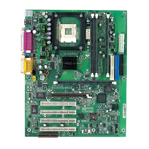
The MS-6523 ATX mainboard is a high-performance computer
mainboard based on Intel®82850 chipset. The MS-6523 is optimized to
support the Intel®Pentium®4 processor for high-end business/personal
desktop markets.
The Intel®Tehama chipset supports 64B cache line size and a 32-bit
host addressing, allowing the processor to access the entire 4GB of the
chipset’s memory address space. It also provides 4x AGP data transfers and
AGP Fast Writes capability.
The Intel®Tehama chipset features a dual channel Direct RDRAM
memory operating in lock-step using RSL technology. It is a highly-flexible
chipset which is designed to extend the basic graphics/multimedia PC
platform up to the mainstream performance desktop platform.
The Intel®82801BA (ICH2) chipset is a highly integrated
multifunctional I/O Controller Hub that provides the interface to the PCI Bus
and integrates many of the functions needed in today’s PC platforms. It
communicates with the host controller over a dedicated hub interface and
provides added flexibility in designing cost-effective system solutions.
This chapter includes the following topics:
Mainboard Specification 1-2
Mainboard Layout 1-4
Quick Components Guide 1-5
Key Features 1-6
MSI Special Features 1-7
1

Chapter 1
1-2
CPU
zSupports Intel®Willamette processor
zSupports1.3GHz,1.4GHz,1.5GHz,1.7GHz,2.0GHzorfaster
Chipset
zIntel®Tehama chipset
-Up to2GB maximummemory (Rambus)
- AGP interface with 4x SBA/Data Transfer
zIntel®ICH2 chipset
- AC’97 Controller Integrated
- 2 Full IDE channels, up to ATA100
- Low pin count interface for SIO
Main Memory
zSupports four 184-pin gold-lead RIMM sockets
zSupportsamaximummemorysizeof 2GB
Slots
zOne AGP (Accelerated Graphics Port) slot
- supports 4x mode
zOne CNR (Communication Network Riser) slot
zFour 32-bit/33MHz Master PCI Bus slots.
zSupports 3.3v/5v PCI bus Interface
On-Board IDE
zAn IDE controller on the Intel®ICH2 chipset provides IDE HDD/CD-ROM
with PIO, Bus Master and Ultra DMA 33/66/100 operation modes.
zCan connect up to four IDE devices
Integrated Super I/O Controller
zWinbond W83627HF-AW I/O controller
- 1 floppy port supports 2 FDDs with 360K, 720K, 1.2M, 1.44M and
2.88M bytes.
- 2 serial ports (COM A + COM B)
- 1 parallel port supports SPP/EPP/ECP mode
- 4 USB ports (Rear*2 / Front*2)
Mainboard Specification

Introduction
1-3
- 1 IrDA connector for SIR
Audio
zICH2 chip integrated
zAC’97 Codec
BIOS
zThe mainboard BIOS provides “Plug & Play” BIOS which detects the
peripheral devices and expansion cards of the board automatically.
zIDE drive auto configure, Advanced Power Management (APM) 1.2,
ACPI 1.0, DMI 2.0, ECC/Parity support, LS-120 support.
Dimension
zATX Form Factor : 12 inches (L) x 9 inches (W) x 4 layers PCB
Mounting
z10 mounting holes

Chapter 1
1-4
Mainboard Layout
MS-6523 ATX Mainboard
AGP Slot
BATT
+
ICH2
J18
J19 JWOL1 JMDM1 JGL1
(Optional)
J16
J17
SYSFAN
JRMS1
JFP1
Codec
JWR1
Winbond
W83627HF
ATX
PowerSupply
CPUFAN
JWR2
PSFAN1
FWH
PCI Slot 4
PCI Slot 3
PCI Slot 2
PCI Slot 1
IDE1
IDE2
CNR
USB
ports
Top :
Parallel Port
Bottom:
COMA
COMB
T : mouse
B: keyboard
J8
J11J10
J12
Top :
Gameport
Bottom:
Line-Out
Line-In
Mic
FDD1
D-LED (Optional)
RIMM2
RIMM3
RIMM4
RIMM1

Introduction
1-5
Quick Components Guide
Component Function Reference
RIMM1~4 Installing RIMM modules See p. 2-4~2-5
Socket 423 Installing CPU See p. 2-2~2-3
CPUFAN Connecting to CPU FAN See p. 2-20
SYSFAN Connecting to SYSTEM FAN See p. 2-20
PSFAN1 Connecting to POWER SUPPLY FAN See p. 2-20
ATX Power Supply Installing power supply See p. 2-6
JWR1 Connecting to 12V ATX power supply See p. 2-7
JWR2 Connecting to 5V/3V ATX power supply See p. 2-7
IDE1& IDE2 Connecting to IDE hard disk drives See p. 2-13
FDD1 Connecting to floppy disk drive See p. 2-12
JUSB1 Connecting to USB interfaces See p. 2-22~2-24
PCI Slot 1~4 Installing expansion cards See p. 2-30
AGP Slot Installing AGP cards See p. 2-30
CNR Slot Installing CNR cards See p. 2-30
JMDM1 Connecting to modem module See p. 2-18
JWOL1 Connecting to LAN module See p. 2-18
JBAT1 Clearing CMOS data See p. 2-25
JFP1 Connecting to case See p. 2-14
JGS1 Connecting to power saving switch See p. 2-17
JGL1 Connecting to power saving LED See p. 2-16
J18 Connecting to IR module See p. 2-19
J12 Connecting to chassis intrusion switch See p. 2-19
JRMS1 Connecting to power switch See p. 2-17
J15 Setting beep output device See p. 2-29
J16 Enabling BIOS flash function See p. 2-28
J17 Clearing BIOS password See p. 2-28
J19 Enabling onboard audio codec See p. 2-27
J20 Setting RDRAM voltage See p. 2-26

Chapter 1
1-6
zATX Form Factor
zCPU: Socket 423 for Intel®Willamette Processors
zMemory: 4 RIMM DIMMs
zSlot: 1 AGP slot, 1 CNR slot, 4 PCI slots
zI/O: 2 serial ports, 1 parallel port, 4 USB 1.1 ports, 1 floppy port, 1 IrDA
connector, 1 Audio/Game port
zUSB Interface: USB 1.1 PC to PC Networking (Optional)
zLAN Wake up Function
zModem (External/Internal) Ring Wake up Function
zD-LED™ --4DiagnosticsLEDs embedded on themainboard(Optional)
zPC AlertTM III system hardware monitor (Optional)
zAudio: Chip integrated
Key Features

Introduction
1-7
PC Alert™ III (Optional)
The PC AlertTM III is a utility you can find in the CD-ROM disk. The
utility is just like your PC doctor that can detect the following PC hardware
status during real time operation:
* monitor CPU & system temperatures
* monitor fan speed(s)
* monitor system voltage
* monitor chassis intrusion
If one of the items above is abnormal, the program main screen will be immedi-
ately shown on the screen, with the abnormal item highlighted in red. This will
continue to be shown,until user disables the warning.
MSI Special Features
Note: Items shown on PC Alert III vary depending on your system’s status.
The MSI special features are designed by MSI R&D which are only available in
MSI mainboards. The MS-6523 mainboard is optionally equipped with PC
Alert™IIIandD-LED™.

Chapter 1
1-8
Features:
zNetwork Management
- Monitoring & remote control
zBasic System Utilities
- Scandisk & Defragment to maintain your HDD
z3D Graphics Design
- Enables a more friendly user interface
zSofwareUtilities
- SoftCooler Optimized Cooling

Introduction
1-9
D-LED™ (Optional)
D-LED Description
System Power ON
- The D-LED will hang here if the processor is damaged or not
installed properly.
Early Chipset Initialization
Memory Detection Test
- Testing onboard memory size. The D-LED will hang if the
memory module is damaged or not installed properly.
Decompressing BIOS image to RAM for fast booting.
Initializing Keyboard Controller.
Testing VGA BIOS
- This will start writing VGA sign-on message to the screen.
Red Green
The D-LED™ uses graphic signal display to help
users understand their system. Four LEDs embedded in
the mainboard provide up to 16 combinations of signals to
debug the system. The 4 LEDs can debug all problems that
fail the system, such as VGA, RAM or other failures. This
special feature is very useful for the overclocking users.
These users can use the feature to detect if there are any
problems or failures.
4
3
2
1
Diagnostic LED
1 2 3 4

Chapter 1
1-10
Processor Initialization
- This will show information regarding the processor (like brand
name, system bus, etc…)
Testing RTC (Real Time Clock)
Initializing Video Interface
- This will start detecting CPU clock, checking type of video
onboard. Then, detect and initialize the video adapter.
BIOS Sign On
- This will start showing information about logo, processor
brand name, etc….
Testing Base and Extended Memory
- Testing base memory from 240K to 640K and extended
memory above 1MB using various patterns.
Assign Resources to all ISA.
Initializing Hard Drive Controller
- This will initialize IDE drive and controller.
Initializing Floppy Drive Controller
- This will initializing Floppy Drive and controller.
Boot Attempt
- This will set low stack and boot via INT 19h.
Operating System Booting

Hardware Setup
2-1
Chapter 2.
Hardware Setup
This chapter provides you with the information about hardware setup
procedures. While doing the installation, be careful in holding the compo-
nents and follow the installation procedures. For some components, if you
install in the wrong orientation, the components will not work properly.
Use a grounded wrist strap before handling computer components.
Static electricity may damage the components.
This chapter contains the following topics:
Central Processing Unit (CPU) 2-2
Memory Installation 2-4
Power Supply 2-6
BackPanel 2-8
Connectors 2-12
Jumpers 2-25
Slots 2-30
2

Chapter 2
2-2
Overheating will seriously damage the CPU
and system, always make sure the cooling fan can work
properly to protect the CPU from overheating.
!
WARNING!
Central Processing Unit: CPU
The mainboard supports Intel®Pentium®4 processor. The mainboard
uses a CPU socket called Socket 423 for easy CPU installation. Make sure
that the CPU has a Heat Sink and a cooling fan attached to prevent
overheating. If you do not find the Heat Sink and cooling fan, contact your
dealer or purchase them before turning on the computer.
1. Pull the lever sideways away
from the socket. Then, raise
the lever up to a 90-degree
angle.
2. Look for the gold arrow.
The gold arrow should point
towards the end of lever.
The CPU will only fit in the
correct orientation.
3. Hold the CPU down firmly,
and then close the lever to
complete the installation.
CPU Installation Procedures Open Lever
Sliding
Plate
Close
Lever
Gold Arrow

Hardware Setup
2-3
CPU Core Speed Derivation Procedure
If CPUClock = 100MHz
Core/Bus ratio = 14
then CPU core speed = Host Clock x Core/Bus ratio
= 100MHzx14
= 1.4GHz
Overclocking
This motherboard is designed to support overclocking.
However, please make sure your components are able to
tolerate such abnormal setting, while doing overclocking.
Any attempt to operate beyond product specifications is
not recommended. We do not guarantee the damages or
risks caused by inadequate operation or beyond product
specifications.
!
WARNING!

Chapter 2
2-4
Themainboardprovides 4gold-leadsocketsfor 184-pinRIMM modules.
To operate properly, at least two RIMM modules must be installed. The
mainboard supports the memory size up to 2 GB.
Memory Installation
RIMM Slots
(RIMM 2~4)
Memory Population Rules
zSupport RIMM only.
zTo operate properly, make sure that the RIMM banks are using the same
type and equal size density memory.
zSupportFSB 100MHz:PC800RIMM.
zSupport up to 32 Direct Rambus Device.
zSupport ECC Single bit Correction and Multiple bit error detection
(Setting in BIOS).
zInstall two RIMM modules either on “RIMM 1and RIMM 2” or on
“RIMM3 and RIMM4” slots.
zIf only two RIMM slots are populated, you must install CRIMM modules
on the other unused RIMM slots.
RIMM Slot
(RIMM 1)

Hardware Setup
2-5
You can install two or four RIMM modules into RIMM slots according
to your needs.
Installing the RIMM Modules
RIMM Module
1. The RIMM slot has 2 Notch Keys, so the RIMM memory module can
only fit in one direction.
2. Insert the RIMM memory module vertically into the RIMM slot. Then
push it in.
3. The plastic clips at sides of the RIMM slot will automatically close.
4. If you won’t insert any RIMM modules on the other two RIMM slots,
you must install CRIMM modules on the empty slots.
NOTCH
Note: To setup the RDRAM voltage for overclocking use, refer to “RDRAM
Over Voltage Jumper: J20”.
CRIMM Module

Chapter 2
2-6
Power Supply
ATX 20-Pin Power Connector
This connector allows you to connect to an ATX power supply. The
power connector supports instant power on function which means that system
will boot up immediately when the power supply connector is inserted on the
board.
ATX
Power Connector
The mainboard supports ATX power supply for the power system.
Before inserting the power supply connectors, always make sure that all com-
ponents are installed properly to ensure that no damage will be caused. To
connect to the ATX power supply, make sure the plug of the power supply is
inserted in the proper orientation and the pins are aligned. Then push down
the power supply firmly into the connector.
10
1
20
11
PIN SIGNAL
11 3.3V
12 -12V
13 GND
14 PS_ON
15 GND
16 GND
17 GND
18 -5V
19 5V
20 5V
PIN SIGNAL
1 3.3V
2 3.3V
3 GND
45V
5 GND
65V
7 GND
8 PW_OK
9 5V_SB
10 12V

Hardware Setup
2-7
ATX 12V Power Connector: JWR1
Attaching the ATX power supply to the connector help offer sufficient
voltage to Pentium 4 CPU. This power connector also supports instant power
on function.
ATX 5V/3V Power Connector: JWR2
The mainboard provides an extra 5V/3V power connector for you to
connect to the ATX power supply.
1
2
3
4
JWR1
JWR2
1
6
PIN SIGNAL
1 GND
2 GND
3 GND
PIN SIGNAL
4 3.3V
5 3.3V
65V
PIN SIGNAL
1 GND
2 GND
3 12V
4 12V

Chapter 2
2-8
The Back Panel provides the following connectors:
Mouse Connector
The mainboard provides a standard PS/2®mouse mini DIN connector
for attaching a PS/2®mouse. You can plug a PS/2®mouse directly into this
connector.
Back Panel
PS/2 Mouse (6-pin Female)
21
3
4
5
6PIN SIGNAL DESCRIPTION
1 Mouse DATA Mouse DATA
2 NC No connection
3 GND Ground
4 VCC +5V
5 Mouse Clock Mouse clock
6 NC No connection
Pin Definition
Mouse
Keyboard USB
Parallel
COM A COM B L-out L-in MIC
Midi/Joystick

Hardware Setup
2-9
Keyboard Connector
The mainboard provides a standard PS/2®keyboard mini DIN connec-
tor for attaching a PS/2®keyboard. You can plug a PS/2®keyboard directly into
this connector.
USB Connectors
The mainboard provides a UHCI (Universal Host Controller Interface)
Universal Serial Bus root for attaching USB devices such as keyboard, mouse
or other USB-compatible devices. You can plug the USB device directly into
ths connector.
21
34
5
6
PS/2 Keyboard (6-pin Female)
PIN SIGNAL DESCRIPTION
1 Keyboard DATA Keyboard DATA
2 NC No connection
3 GND Ground
4 VCC +5V
5 Keyboard Clock Keyboard clock
6 NC No connection
Pin Definition
USB Ports
1 2 3 4
5 6 7 8
PIN SIGNAL DESCRIPTION
1 VCC +5V
2 -Data 0 Negative Data Channel 0
3 +Data0 Positive Data Channel 0
4 GND Ground
5 VCC +5V
6 -Data 1 Negative Data Channel 1
7 +Data 1 Positive Data Channel 1
8 GND Ground
USB Port Description

Chapter 2
2-10
Parallel Port Connector
The mainboard provides a 25-pin female centronic connector for LPT.
A parallel port is a standard printer port that supports Enhanced Parallel Port
(EPP) and Extended Capabilities Parallel Port (ECP) mode.
13 1
1425
PIN SIGNAL DESCRIPTION
1 STROBE Strobe
2 DATA0 Data0
3 DATA1 Data1
4 DATA2 Data2
5 DATA3 Data3
6 DATA4 Data4
7 DATA5 Data5
8 DATA6 Data6
9 DATA7 Data7
10 ACK# Acknowledge
11 BUSY Busy
12 PE Paper End
13 SELECT Select
14 AUTOFEED# Automatic Feed
15 ERR# Error
16 INIT# Initialize Printer
17 SLIN# Select In
18 GND Ground
19 GND Ground
20 GND Ground
21 GND Ground
22 GND Ground
23 GND Ground
24 GND Ground
25 GND Ground1
PinDefinition
This manual suits for next models
1
Table of contents
Other MSI Motherboard manuals

MSI
MSI B85M-E33 V2 User manual

MSI
MSI H110M-A PRO M2 User manual

MSI
MSI LPX ZX4 User manual

MSI
MSI MEG Z590 GODLIKE User manual

MSI
MSI A88X-G45 GAMING User manual

MSI
MSI G52-74111X2 User manual

MSI
MSI Z77A-G45 GAMING series User manual

MSI
MSI Z490-A PRO User manual

MSI
MSI MEG Z490 ACE User manual

MSI
MSI MS-98D7 User manual

MSI
MSI K8N SLI-F User manual

MSI
MSI KT6 Delta-FIS2R User manual

MSI
MSI K9VGM-V Series User manual

MSI
MSI Intel RAID User manual

MSI
MSI Z170A SLI PLUS User manual

MSI
MSI C847MS-E33 Series User manual

MSI
MSI FUZZY CX700 User manual

MSI
MSI Z170A KRAIT GAMING User manual

MSI
MSI 990XA-GD55 series User manual

MSI
MSI Z87M-G43 Series User manual