MSI 848P-V2 Series User manual

i
FCC-BRadio FrequencyInterferenceStatement
Thisequipment hasbeen tested and found tocomplywiththe limitsforaclassBdigitaldevice, pursuantto
part 15 of theFCC rules.Theselimitsaredesigned toprovidereasonableprotection against harmful
interferencewhen theequipment is operated inacommercialenvironment. Thisequipment generates, uses
and can radiateradiofrequencyenergyand, if not installed and used inaccordancewiththe instruction
manual, maycauseharmfulinterferencetoradiocommunications. Operation of this equipment ina
residentialarea is likelytocauseharmfulinterference, inwhichcasethe userwillbe required tocorrect the
interferenceat his ownexpense.
Notice1
The changesormodificationsnot expresslyapprovedbythe partyresponsibleforcompliancecouldvoidthe
user sauthoritytooperatethe equipment.
Notice2
Shielded interfacecablesand A.C. powercord, if any, must be used inordertocomplywiththe emission
limits.
VOIRLANOTICEDNSTALLATIONAVANTDERACCORDERAU RESEAU.
Micro-StarInternational
MS-7157
This devicecomplieswithPart 15 of the FCC Rules. Operation is subject tothe following twoconditions:
(1)this devicemaynot causeharmfulinterference, and
(2)this devicemustacceptanyinterferencereceived,including interferencethatmaycauseundesired
operation
G52-M7157X1

ii
CopyrightNotice
The materialinthisdocument is the intellectualpropertyofMICRO-STARINTERNATIONAL. Wetakeevery
careinthe preparation of this document, butno guarantee is given astothe correctness of itscontents. Our
productsareundercontinualimprovement andwereservethe right tomakechangeswithout notice.
Trademarks
All trademarksarethe propertiesof theirrespectiveowners.
AMD, Athlon™Athlon™XP,Thoroughbred™andDuron™areregistered trademarksofAMD Corporation.
Intel®and Pentium®areregistered trademarksofIntelCorporation.
PS/2and OS®2areregistered trademarksofInternationalBusiness MachinesCorporation.
Microsoft®is aregistered trademarkofMicrosoft Corporation.Windows®98/2000/NT/XPareregistered
trademarksofMicrosoft Corporation.
NVIDIA,the NVIDIAlogo, DualNet, and nForceareregistered trademarksortrademarksof NVIDIA
Corporation inthe United Statesand/orothercountries.
Netware®is aregistered trademarkof Novell,Inc.
Award®is aregistered trademarkof PhoenixTechnologiesLtd.
AMI®is aregistered trademarkofAmerican MegatrendsInc.
Kensington andMicroSaverareregistered trademarksof the KensingtonTechnologyGroup.
PCMCIAandCardBusareregistered trademarksof the PersonalComputerMemoryCardInternational
Association.
Revision History
Revision Revision HistoryDate
V1.0First releaseMarch2005

iii
SafetyInstructions
1.Alwaysread thesafetyinstructionscarefully.
2.Keep this UserManualforfuturereference.
3.Keep this equipment awayfromhumidity.
4.Laythis equipment on areliableflat surfacebeforesetting it up.
5.The openingson the enclosureareforairconvection henceprotectsthe equipment fromoverheating.
Donot coverthe openings.
6.Makesurethe voltage of thepowersourceandadjust properly110/220Vbeforeconnecting the
equipment tothe powerinlet.
7.Placethe powercordsuchawaythat peoplecan not step on it. Donot placeanything overthepower
cord.
8.AlwaysUnplug thePowerCordbeforeinserting anyadd-on cardormodule.
9.All cautionsand warningson the equipment shouldbe noted.
10.Neverpouranyliquidintothe opening that coulddamage orcauseelectricalshock.
11.Ifanyof the following situationsarises, get the equipment checkedbyaservicepersonnel:
-The powercordorplug is damaged.
-Liquidhaspenetrated intothe equipment.
-The equipment hasbeen exposed tomoisture.
-The equipment doesnot workwell oryou can not get it workaccording tothe User Manual.
-The equipment hasdropped and damaged.
-The equipment hasobvioussign of breakage.
12.Donot leavethis equipment inan environment unconditioned, storage temperatureabove60°C (140°F),
it maydamage the equipment.

iv
TableofContents
English.....................................................................1
Fran ais...................................................................13
Deutsch....................................................................25
体中文 ...................................................................37
體中文 ...................................................................49
日本語.......................................................................61

1
Introduction
Thankyouforchoosing848P-V2Series(MS-7157v1.x)ATXmainboard.The848P-V2Seriesis
based on Intel®848P&Intel ICH5chipsetsforoptimalsystemefficiency. Designed tofit the
advancedIntel P4Prescott processorsin478pin package,the848P-V2Seriesdeliversahigh
performanceandprofessional desktop platformsolution.
Layout

2
Specifications
CPU
lSupportsIntel Pentium4Prescottprocessorsin478pinpackage.
lFSB 400/ 533 / 800MHz(FSB400forNorthwoodCeleron only).
lSupportsupto3.4GHzorhigherspeed.
(Forthelatest information aboutCPU,pleasevisit
http://www.msi.com.tw/program/products/mainboard/mbd/pro_mbd_cpu_support.php)
Chipset
lIntel 848Pchipset
-SupportsFSB 800/533/400MHz.
-SupportsAGP8Xinterface.
-SupportsDDR400/333/266memoryinterface.
lIntel ICH5chipset
-Hi-SpeedUSB (USB2.0)controller,480Mb/sec,8ports.
-2Serial ATA/150 ports.
-2channel UltraATA100busMasterIDEcontroller.
-PCIMasterV2.3, I/OAPIC.
-SupportsbothACPI and legacyAPMpowermanagement.
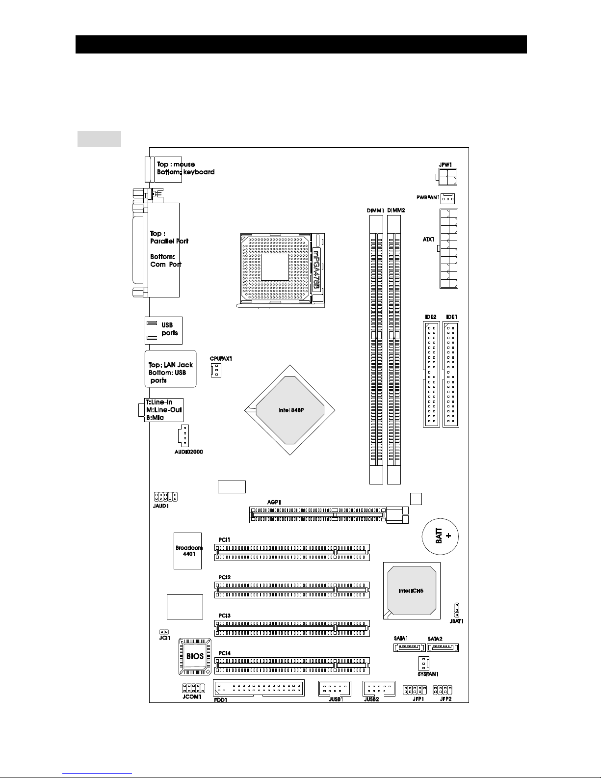
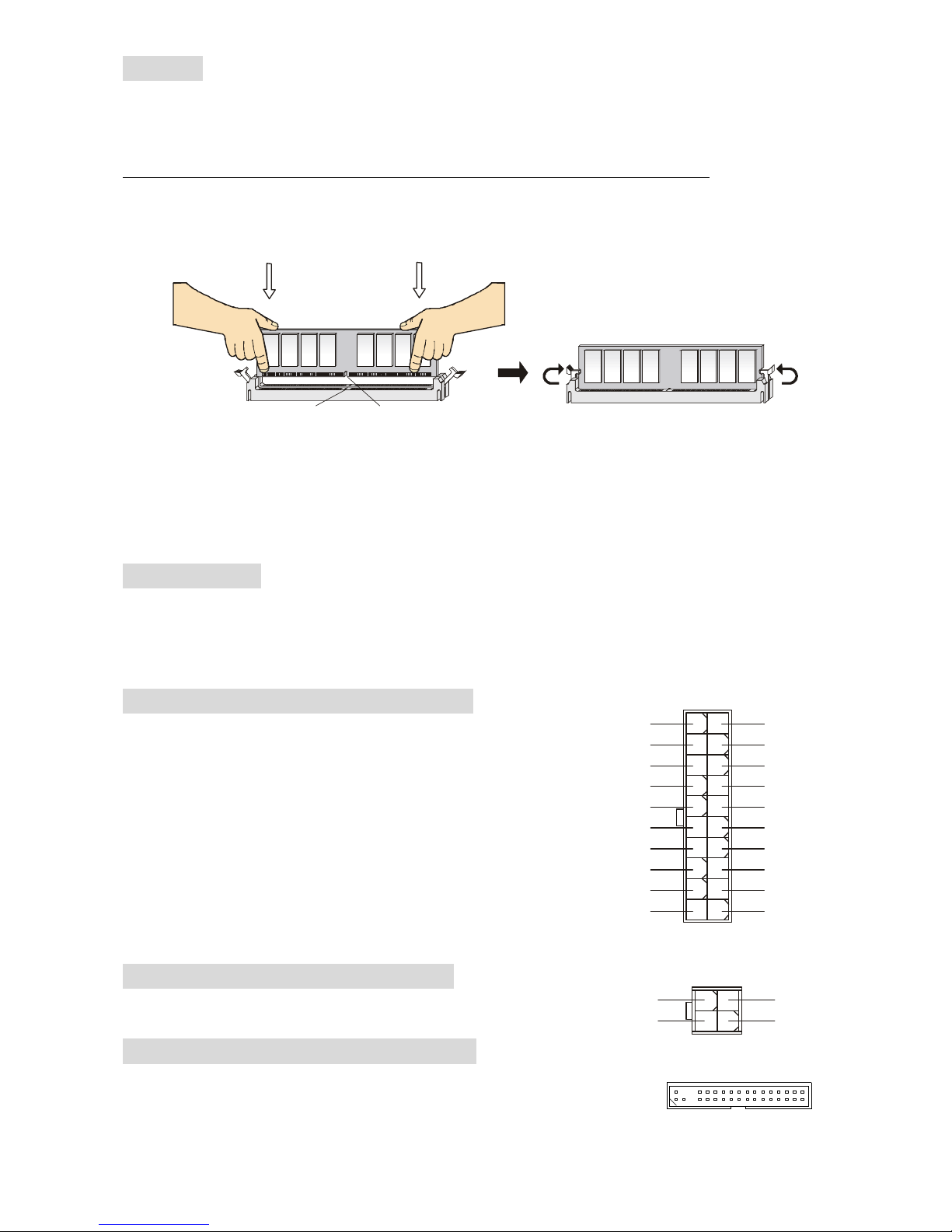
Main Memory
lSupportstwounbuffered DIMMof 2.5Volt DDR SDRAM.
lSupportsupto2GBmemorysizewithoutECC.
lSupportsSinglechannel DDR266/333/400MHz.
(Fortheupdatedsupportingmemorymodules,pleasevisit
http://www.msi.com.tw/program/products/mainboard/mbd/pro_mbd_trp_list.php)
Slots
lOneAGPslotsupports8x/4xat1.5V(3.3Visnot supported).
lFour32-bitv2.3MasterPCIbusslots(support3.3v/5vPCIbusinterface).
On-Board IDE
lDual UltraDMA66/100IDEcontrollersintegrated inICH5.
-SupportsPIO, BusMasteroperation modes.
-CanconnectuptofourUltraATAdrives.
lSerialATA/150controllerintegrated inICH5.
-Upto150MB/sectransferspeeds.
-CanconnectuptotwoSerialATAdrives.
On-BoardPeripherals
lOn-BoardPeripheralsinclude:
-1floppyportsupports1FDD with360K,720K,1.2M,1.44Mand 2.88Mbytes
-1serialportontherearpanel
-1serialportwithpinheader(throughexternalcable)
-1parallel portsupportsSPP/EPP/ECPmode
-8USB2.0ports(Rear*4/ Front *4)
-1Line-In/ Line-Out/ Mic-In
-1RJ45LANjack
Audio
lAC97linkcontrollerintegratedinIntel®848Pchipset.
l5.1-channel audiocodecADIAD1888.
-CompliancewithAC97v2.3Spec.
-MeetPC2001audioperformancerequirement.

3
LAN
lBroadcom 4401
-Integrated FastEthernetMACandPHYinonechip.
-Supports10Mb/s,100Mb/s.
-CompliancewithPCI2.2.
-SupportsACPIPowerManagement.
BIOS
lThemainboardBIOSprovides “Plug &Play”BIOSwhichdetectstheperipheral devices
andexpansioncardsof theboardautomatically.
lThe mainboardprovidesaDesktop ManagementInterface(DMI)function whichrecords
yourmainboardspecifications.
Dimension
lATXFormFactor:30.5cm(L)x17.5cm(W).
Mounting
l6mountingholes.

4
Rear Panel
The rearpanelprovidesthefollowing connectors:
HardwareSetup
ThischaptertellsyouhowtoinstalltheCPU,memorymodules,andexpansioncards,aswellas
howtosetupthejumperson themainboard.It alsoprovidestheinstructionson connectingthe
peripheral devices, suchasthemouse,keyboard,etc.Whiledoingtheinstallation,becarefulin
holdingthecomponentsandfollowtheinstallation procedures.
Central ProcessingUnit: CPU
The mainboardsupportsIntel®Pentium4Prescottprocessor.ThemainboardusesaCPUsocket
called socket478.When youareinstallingtheCPU,makesuretoinstallthecoolertoprevent
overheating.If you donothavetheCPUcooler, contactyourdealertopurchaseandinstallthem
beforeturningon thecomputer.
(Forthelatest information aboutCPU,pleasevisit
http://www.msi.com.tw/program/products/mainboard/mbd/pro_mbd_cpu_support.php.)
MSI RemindsYou...
Overheating
Overheatingwill seriouslydamagethe CPUandthesystem,always makesurethe coolingfan
can workproperlytoprotecttheCPUfromoverheating.
Overclocking
Thismainboardisdesignedtosupportoverclocking. However,pleasemakesureyour
componentsareable totoleratesuchabnormalsetting, while doingoverclocking.Anyattempt to
operatebeyondproduct specificationsisnotrecommended. Wedonotguarantee thedamages
orrisks caused byinadequateoperationorbeyondproduct specifications.
Memory Speed/CPUFSBSupportMatrix
Memory
FSB DDR 266 DDR 333 DDR 400
400MHz OK N/A N/A
533MHz OK OK N/A
800MHz N/A OK OK

5
CPUInstallation Procedures forSocket478
1.Pleaseturnoffthepowerandunplug thepowercordbeforeinstallingtheCPU.
2.Pulltheleversidewaysawayfromthesocket.Makesuretoraisetheleveruptoa
90-degree angle.
3.Lookforthegoldarrow.Thegoldarrowshouldpointtowardstheleverpivot.TheCPUcan
onlyfitinthecorrectorientation.
4.IftheCPUiscorrectlyinstalled, thepinsshouldbecompletelyembedded intothesocket
andcan notbeseen.Pleasenotethat anyviolation of thecorrect installation procedures
maycausepermanentdamagestoyourmainboard.
5.Press theCPUdownfirmlyintothesocket and closethelever.Asthe CPUislikelyto
movewhiletheleverisbeingclosed,alwaysclosetheleverwithyourfingerspressing
tightlyon top oftheCPUtomakesuretheCPUisproperlyand completelyembedded into
thesocket.
InstallingtheCPUFan
Asprocessortechnologypushestofasterspeedsandhigherperformance,thermalmanagement
becomesincreasinglyimportant.Todissipateheat,youneedtoattachtheCPUcoolingfanand
heatsinkon top oftheCPU.FollowtheinstructionsbelowtoinstalltheHeatsink/Fan:
1.LocatetheCPUand itsretention mechanismon themotherboard.
2.Positiontheheatsinkontotheretention mechanism.
3.Mount thefan on top oftheheatsink. Press downthefanuntilitsfourclipsgetwedged in
theholesoftheretention mechanism.
4.Press thetwoleversdowntofastenthefan.EachlevercanbepresseddowninonlyONE
direction.
5.Connectthefanpowercablefromthemounted fantothe3-pinfan powerconnectoron
theboard.
MSI RemindsYou...
Overheating
Overheatingwill seriouslydamagethe CPUandsystem,always makesurethe coolingfancan
workproperlytoprotecttheCPUfromoverheating.
Replacing theCPU
WhilereplacingtheCPU,always turnoff the ATXpowersupplyorunplugthepowersupply’s
powercordfromgroundedoutlet first toensurethesafetyof CPU.

6
Memory
The mainboardprovidestwo184-pinunbuffered DDR266/ DDR333/ DDR400DDR SDRAM,
andsupportsthememorysizeupto2GB.Tooperateproperly,atleastoneDIMMmodulemust
beinstalled.(Fortheupdated supportingmemorymodules,pleasevisit
http://www.msi.com.tw/program/products/mainboard/mbd/pro_mbd_trp_list.php)
Installat least oneDIMMmoduleon theslots.Memorymodulescan beinstalled ontheslotsin
anyorder.You can install eithersingle-ordouble-sided modulestomeet yourownneeds.
Installing DDRModules
1.The DDRDIMMhasonlyonenotchon thecenterofmodule.Themodulewillonlyfit inthe
rightorientation.
2.InserttheDIMMmemorymoduleverticallyintotheDIMMslot.Then pushitinuntilthe
golden fingeron thememorymoduleisdeeplyinsertedinthesocket.
3.The plasticclipat eachsideoftheDIMMslot willautomaticallyclose.
Power Supply
The mainboardsupportsATXpowersupplyforthepowersystem.Beforeinsertingthepower
supplyconnector, alwaysmakesurethatallcomponentsareinstalledproperlytoensurethatno
damagewill becaused.A300Worabovepowersupplyissuggested.
ATX20-PinPower Connector:ATX1
Thisconnectorallowsyoutoconnect an ATX20-pinpower
supply.Toconnect theATX20-pin powersupply,makesure
theplugofthepowersupplyisinserted in theproper
orientation andthepinsarealigned.Then pushdownthe
powersupplyfirmlyintotheconnector.
ATX12VPower Connector:JPW1
This12Vpowerconnectorisused toprovidepowertotheCPU.
FloppyDisk DriveConnector:FDD1
The mainboardprovidesastandardfloppydisk driveconnectorthat
supports360K,720K,1.2M, 1.44Mand2.88Mfloppydisktypes.
Notch
Volt
1
10
11
20
+3.3V
+3.3V
-12V
+3.3V
GND GND
PS-ON#
+5V
GND GND
GND +5V
GND GND
-5V
PWROK
+5V 5VSB
+5V +12V
1
3
4
2
GND
12V
GND
12V

7
IDEConnector:IDE1/IDE2
The mainboardhasdualUltraDMA66/100controllerthatprovidesPIOmode0~4, Bus
Master, and UltraDMA66/100function. Youcan connect uptofourharddiskdrives,
CD-ROM,120MBFloppyandotherdevices.
The first harddriveshouldalwaysbeconnected toIDE1.IDE1can connectaMaster
andaSlavedrive. Youmust configuresecondharddrivetoSlavemodebysettingthe
jumperaccordingly.
MSI RemindsYou...
If youinstall twoharddisks ononecable, youmust configuretheseconddrivetoSlavemode by
setting itsjumper. Refertotheharddisk documentation suppliedbyharddisk vendorsforjumper
setting instructions.
SerialATAConnectors controlledbyIntel®ICH5:SATA1/SATA2
The mainboardprovidesdual high-speedSerialATAinterfaceports.The ports
supper1st generation SerialATAdataratesof150MB/sandarefullycompliant
withSerial ATA1.0specifications.EachSerial ATAconnectorcan connectto1harddisk device.
MSI RemindsYou...
Pleasedo not fold theserialATAcable in a90-degree angle, whichwill causetheloss of data
duringtransmission.
CD-In Connector:AUDIO2000
The connectorisforCD-ROMaudioconnector.
ChassisIntrusionSwitch Connector:JCI1
Thisconnectorisconnected toa2-pin chassisswitch. JCI1is
compliantwithIntel®Front PanelI/OConnectivityDesignGuide.
L
R
GND

8
FanPower Connectors:CPUFAN1/PWRFAN1/SYSFAN1
The 3-pinCPUFAN1(processorfan)and3-pin
PWRFAN1(powersupplyfan)/ SYSFAN1
(systemfan)support systemcoolingfanwith
+12V. CPUFAN1can supportthree-orfour-pin
head connector.
Whenconnectingthewiretotheconnectors,alwaystakenotethat thered wireisthepositive
andshouldbeconnectedtothe+12V,theblackwireisGround andshouldbeconnected toGND.
IfthemainboardhasaSystemHardwareMonitorchipseton-board, you must useaspecially
designedfan withspeedsensortotakeadvantageof theCPUfan control.
MSI RemindsYou...
Always consultthevendorsfortheproperCPUcoolingfan.
FrontPanel Connectors:JFP1/JFP2
The mainboardprovidestwofrontpanel connectorsfor
electrical connection tothefront panel switchesandLEDs.
JFP1iscompliantwithIntel®FrontPanel I/OConnectivity
DesignGuide.
FrontPanelAudio Connector:JAUD1
The frontpanel audioconnectorallowsyouto
connect tothefrontpanel audioandis
compliantwithIntel®Front PanelI/O
ConnectivityDesignGuide.
MSI RemindsYou...
If youdonotwanttoconnecttothefrontaudio header,pins5&6,9&10have
tobe jumperedin ordertohavesignaloutputdirectedtotherearaudioports.
Otherwise,theLine-Out connectorontheback panelwill not function.
FrontUSBConnector:JUSB1/JUSB2
The mainboardprovidestwostandardUSB 2.0pin headers
JUSB1&JUSB2. USB2.0technologyincreasesdatatransfer
rateuptoamaximumthroughputof 480Mbps,whichis40
timesfasterthanUSB 1.1,andisidealforconnecting
high-speedUSBinterfaceperipheralssuchasUSB HDD,
digital cameras,MP3players, printers,modems,etc.
MSI RemindsYou...
Pleasenotethat thepinsof VCC&GNDmustbe connected correctlyorit maycausesome
damage
GND
+12V
Sensor
+12V
Sensor
+12V
GND
GND
Sensor
CPUFAN1 SYSFAN1PWRFAN1
JFP1
Power
LED
HDD
LED Reset
Switch
Power
Switch
1 9
2
10
JFP2
Power
LED
Speaker
1
7
2
8
(2)AUD_GND
AUD_VCC
AUD_RET_R
Key
AUD_RET_L(10)
(1)AUD_MIC
AUD_MIC_BIAS
AUD_FPOUT_R
HP_ON
AUD_FPOUT_L(9)

9
Serial PortConnector:JCOM1(Optional)
The mainboardoffersone9-pinmaleDINconnectorCOM1(ontherear
panel), andoneoptional serial port JCOM1.Bothare16550Ahigh speed
communication portsthat send/receive16bytesFIFOs. Youcanattacha
serial mouseorotherserial devicedirectlytothem.
PIN SIGNAL DESCRIPTION PIN SIGNAL DESCRIPTION
1
3
5
7
9
DCD
SOUT
GND
RTS
RI
DataCarryDetect
ReceiveDataTransmit
Data
Request ToSend Ring
Indicate
2
4
6
8
10
SIN
DTR
DSR
CTS
X
Serialinorreceivedata
Serialout ortransmit data
DataSetReady
ClearToSend
X
Clear CMOSJumper:JBAT1
ThereisaCMOSRAMon boardthathasapowersupplyfrom
external batterytokeepthedataofsystemconfiguration.Withthe
CMOSRAM, thesystemcan automaticallyboot OSeverytimeitis
turnedon.If you want toclearthesystemconfiguration,usethe
JBAT1(ClearCMOSJumper)tocleardata. Followtheinstructions
in theimagetoclearthedata.
MSI RemindsYou...
YoucanclearCMOSbyshorting2-3pin while thesystemisoff. Thenreturnto1-2pin position.
Avoid clearingtheCMOSwhilethesystemison, whichwill damagethe mainboard.
AGP(Accelerated Graphics Port) Slot
The AGPslotallowsyoutoinserttheAGP
graphics card.AGPisan interfacespecification
designedforthethroughput demandsof 3Dgraphics. It introducesa66MHz,32-bitchannelfor
thegraphics controllertodirectlyaccess mainmemory.Theslot supportsAGPcardfor8x/4xat
1.5v(3.3visnotsupported).
PCI (PeripheralComponentInterconnect) Slots
The PCIslotsallowyoutoinsert theexpansion cards
tomeetyourneeds.When adding orremoving
expansioncards,makesurethatyou unplugthe
powersupplyfirst. Meanwhile,readthedocumentationfortheexpansioncardtomakeany
necessaryhardwareorsoftwaresettingsfortheexpansioncard, suchasjumpers, switchesor
BIOSconfiguration.
PCI InterruptRequestRouting
The IRQ,abbreviation of interrupt requestlineandpronouncedI-R-Q,arehardwarelinesover
whichdevicescansendinterrupt signalstothemicroprocessor.ThePCI IRQpinsaretypically
connected tothePCIbusINTA#~INT D#pinsasfollows:
Order1 Order2 Order3 Order4
PCISlot 1 INTB# INTC# INTD# INTA#
PCISlot 2 INTC# INTD# INTA# INTB#
PCISlot 3 INTD# INTA# INTB# INTC#
PCISlot 4 INTA# INTB# INTC# INTD#

10
BIOSSetup
Poweron thecomputerandthesystemwillstart POST (PowerOnSelfTest)process.When the
messagebelowappearson thescreen,press <DEL>keytoenterSetup.
DEL:Setup
Ifthemessagedisappearsbeforeyourespondand you stillwishtoenterSetup, restartthe
systembyturning it OFF andOnorpressingtheRESETbutton.You mayalsorestart thesystem
bysimultaneouslypressing<Ctrl>,<Alt>, and <Delete> keys.
MainPage
Standard CMOSFeatures
Usethismenuforbasicsystemconfigurations, suchastime, dateetc.
Advanced BIOSFeatures
UsethismenutosetuptheitemsofAwardspecial enhancedfeatures.
AdvancedChipsetFeatures
Usethismenutochangethevaluesin thechipset registersandoptimizeyoursystem
performance.
IntegratedPeripherals
Usethismenutospecifyyoursettingsforintegrated peripherals.
PowerManagementSetup
Usethismenutospecifyyoursettingsforpowermanagement.
PnP/PCI Configurations
Thisentryappearsif yoursystemsupportsPnP/PCI.
H/W Monitor
Thisentryshowsthestatusof yourCPU,fan,warning foroverallsystemstatus.
Frequency/VoltageControl
Usethismenutospecifyyoursettingsforfrequency/voltagecontrol.
LoadOptimizedDefaults
Usethismenutoloadthedefault valuesset bythemainboardmanufacturerspecificallyfor
optimalperformanceofthemainboard.

11
BIOSSettingPassword
Usethismenutoset password.
Save&ExitSetup
SavechangestoCMOSandexit setup.
ExitWithoutSaving
Abandonall changesand exitsetup.
Frequency/VoltageControl
CurrentCPUClock
It showsthecurrent clockofCPU. Read-only.
CPUClockRatio
Thisitemallowsyou toadjusttheCPUratio. ItmightbelockedbyCPUhardwareandthisitem
willbehided.
DDRPowerVoltage
Adjusting theDDR voltagecanincreasetheDDR speed.Anychangesmadetothissettingmay
causeastabilityissue, sochangingtheDDR voltageforlong-termpurposeisNOT
recommended.
AGPPowerVoltage
AGPvoltageisadjustableinthefield,allowing you toincreasetheperformanceof yourAGP
displaycardwhen overclocking,butthestabilitymaybeaffected.Settingoptions:1.5Vto1.8Vat
0.05Vincrement.
AutoDetectPCI Clk
Thisitemisused toautodetectthePCI slots.When setto[Enabled], thesystemwill remove
(turnoff)clocksfromemptyPCI slotstominimizetheelectromagneticinterference(EMI).
Settings: [Enabled], [Disabled].

12
SpreadSpectrum
Whenthemotherboardsclockgeneratorpulses,theextremevalues(spikes)ofthepulses
createsEMI (ElectromagneticInterference).TheSpreadSpectrumfunction reducestheEMI
generatedbymodulatingthepulsessothatthespikesofthepulsesarereduced toflattercurves.
IfyoudonothaveanyEMIproblem,leavethesettingat[Disabled] foroptimal systemstability
andperformance.But if youareplagued byEMI, selectthedesiredrangeforEMI reduction.
RemembertodisableSpreadSpectrumfunction if you areoverclocking,becauseeven aslight
jittercan introduceatemporaryboostinclockspeedwhichmayjustcauseyouroverclocked
processortolockup.
CPUClock
Thisitemallowsyou toselecttheCPUFront SideBusclockfrequency(inMHz)andoverclock
theprocessorbyadjusting theFSBclocktoahigherfrequency.
LoadBIOSDefaults
Youcanloadthedefault valuesprovided bythemainboardmanufacturerforthestable
performance.

13
Introduction
Félicitations,vousvenezd acquérirunecartemèreATX848P-V2Series(MS-7157 v1.x)La
848P-V2SeriesestbaséesurlesChipsetsIntel®848P&Intel ICH5offrantun systèmetrès
performant.LacartefonctionneaveclesprocesseursIntel P4Prescott 400/533/800MHz
(Socket478),est trèsperformanteetoffreunesolution adaptéetantauxprofessionnelsqu aux
particuliers.
Schéma

14
Spécificités
CPU
lSupportelesprocesseursIntel®P4Northwood/Prescott (Socket478)jusquà 3.4ghz
(Pourlesdernièresmises àjoursconcernantlesCPU,vouspouvezvisiter:
http://www.msi.com.tw/program/products/mainboard/mbd/pro_mbd_cpu_support.php.)
Chipset
lChipset Intel 848P
-SupporteFSB800/533/400MHz.
-Supportel interfaceAGP8X.
-Supportel interfacedemémoireDDR 400/333/266.
lChipset Intel ICH5
-contrôleurHi-SpeedUSB(USB2.0),480Mb/sec,8ports.
-2portsSerial ATA/150.
-2contrôleursIDEbusMasterchannel UltraATA100.
-PCIMasterV2.3, I/OAPIC.
-Supporte àlafoisl ACPIetlagestion del alimentation (APM).
MémoirePrincipale
lSupportedeuxDIMMunbuffered de2.5VoltDDR SDRAM.
lSupportejusqu à 2GBdemémoirenon ECC.
lSupporteleseulcanal DDR266/333/400MHz.
(Pournuemise àjoursurlesmodulesdemémoiressupportés,veuillezvisiter
http://www.msi.com.tw/program/products/mainboard/mbd/pro_mbd_trp_list.php )
Slots
lUnslotAGPsupportant8x/4x à1.5V(le3.3Vnest passupporté).
lQuatreslotsPCIbusMaster32-bitv2.3(supportel interfacebusPCI3.3v/5v).
IDEIntégré
lDeuxcontrôleursIDEUltraDMA66/100 intégrésdansICH5.
-SupportelesmodesopératoiresPIO,BusMaster.
-Possibilitédeconnecterjusqu à quatredisquesUltraATA.
lContrôleurSerial ATA/150 intégrédansICH5.
-Vitessedetransfert jusqu à 150MB/sec.
-Peut connecterjusqu à deuxdisquesSerialATA.
PériphériquesIntégrés
lPériphériquesIntégrésInclus:
-1port floppysupportant 1FDDavec360K,720K, 1.2M,1.44Met2.88Mbytes
-1port sériesurlepanneauarrière
-1port sériesurbroches àtraversuncâbleexterne
-1portparallèlesupportantlesmodesSPP/EPP/ECP
-8portsUSB 2.0(Arrière*4/Avant*4)
-1Line-In/ Line-Out/ Mic-In
-1RJ45LANjack
Audio
lContrôleurAC97linkintegrédanslechipset Intel®848P.
l5.1canauxaudiocodecADIAD1888.
-CompatibleaveclesSpecAC97 v2.3.
-RépondauxexigencesaudioPC2001.

15
LAN
lBroadcom 4401
-Fast EthernetMACetPHYIntegrédansunepuce.
-Supporte10Mb/s,100Mb/s.
-CompatibleavecPCI 2.2.
-Supportel ACPIPowerManagement.
BIOS
lLacarteprocureunBIOS “Plug&Play”quidétecteautomatiquementlescartes
dextension ou lespériphériques.
lLacarteoffreuneinterfaceDMI (Desktop ManagementInterface)quienregistreles
spécificitésdelacartemère.
Dimension
lFormatATX: 30.5cm(L)x17.5cm(W).
Montage
l6trousdemontage.

16
PanneauArrière
Lepanneauarrièreprocurelesconnecteurssuivants:
InstallationMatériel
CechapitrevousindiquecommentinstallerleCPU,lamémoireainsiquelescartesd extension
ou encoreleréglagedescavaliersprésentssurlacarte. Vousaurezaussidesinstructions
relatives àlaconnexiondespériphériquestelsquelasouris,leclavieretc.Lorsdel installation
veuillezfairetrèsattention aux élémentscomposantlacartemèreet suivezbien lesprocédure
dinstallations.
Central ProcessingUnit: CPU
LacartemèresupportelesprocesseursIntelPentium4/Celeron(D)(socket478). Lacartemère
utiliseunsocketappeléPGA478permettantuneinstallation aiséeduprocesseur. Lorsde
linstallation du CPU,assurez-vousqueleCPUpossèdebien un systèmederefroidissement
constituéd undissipateur+ventilateurpermettantladissipation delachaleur. Pourconnaîtrele
modèledeventilateurnécessaire àlabonneutilisation devotresystèmen hésitezpas à
contactervotrerevendeur. (PourconnaîtrelesdernièresinformationsconcernantleCPU,
veuillezvisiter
(http://www.msi.com.tw/program/products/mainboard/mbd/pro_mbd_cpu_support.php)
ExempledeDérivationdu CPUCore Speed
SiHorlogeCPU=133MHz
RationCore/Bus=23
AlorsVitesseCPU=HorlogexratioCore/Bus
=133MHzx23
=3.06 GHz
Tableaudesupportdevitesse mémoire /CPUFSB
Memory
FSB DDR 266 DDR 333 DDR 400
400MHz OK N/A N/A
533MHz OK OK N/A
800MHz N/A OK OK
Procédure d’InstallationduCPUSocket478
1.Veuillez éteindreou débrancherlePCavantd installerleCPU.
2.Tirerlelevierquisetrouvesurlecôtédusocket. Assurez-vousquecelui-ciest bienrelevé
(position 90°).
3.ChercherlamarquedoréesurleCPU.Lamarquedoréedoitpointerverslepivotdulevier.
This manual suits for next models
1
Table of contents
Languages:
Other MSI Motherboard manuals

MSI
MSI K8NNeo4 Platinum Series User manual

MSI
MSI B450I GAMING PLUS AC User manual

MSI
MSI H270 PC MATE User manual

MSI
MSI KT4 Ultra User manual

MSI
MSI MS-7502 Series User manual

MSI
MSI P45T-C53 Series User manual

MSI
MSI MS-7222 User manual

MSI
MSI z170a GAMING M9 ACK User manual

MSI
MSI P45 Neo3 V2 Series User manual

MSI
MSI G52-MA00353 User manual

MSI
MSI KT880 Delta User manual

MSI
MSI MS-6533 User manual

MSI
MSI 645 Ultra MS-6547 User manual

MSI
MSI B350M MORTAR User manual

MSI
MSI H170M PRO-DH User manual

MSI
MSI MICRO ATX ZX14 User manual

MSI
MSI MS-7043 User manual

MSI
MSI Wind Board 330 User manual

MSI
MSI PRO B550-P GEN3 User manual

MSI
MSI X99A SLI PLUS User manual