MSI Hybrid Triplex User manual

Technical Manual
MSI Hybrid™ Well Service Pump
Triplex and Quintuplex Models
MSI – A Division of Dixie Iron Works, Ltd.
300 W. Main St.
Alice, TX 78332
www.diwmsi.com
(800) 242-0059
Revision K

TABLE OF CONTENTS
SECTION 1 WARNINGS ...................................................................................................................... 1
SECTION 2 GENERAL DESCRIPTION ............................................................................................ 2
2.1 PUMP DESCRIPTION ......................................................................................................................... 2
2.2 PUMP SPECIFICATIONS ..................................................................................................................... 2
2.3 PUMP PERFORMANCE....................................................................................................................... 3
SECTION 3 PRESERVATION............................................................................................................. 7
3.1 PRESERVATION CONSIDERATIONS.................................................................................................... 7
3.2 PRESERVATION FOR SHIPPING .......................................................................................................... 7
3.3 PRESERVATION FOR STORAGE ......................................................................................................... 7
3.4 PRESERVATION BETWEEN JOBS ....................................................................................................... 9
SECTION 4 INSTALLATION............................................................................................................ 10
4.1 PUMP DIMENSIONS,CG, LIFTING POINTS,AND MOUNTING REQUIREMENTS ................................. 10
4.2 MAINTENANCE SPACE REQUIREMENTS.......................................................................................... 16
4.3 PUMP SERVICE TOOLS ................................................................................................................... 18
4.4 PUMP DRIVE CONNECTIONS AND LOCATIONS................................................................................ 20
4.5 FLUID PUMPING CONNECTIONS AND PRESSURE RELIEF CONSIDERATIONS .................................... 25
4.6 PUMP LUBRICATION AND INSTRUMENT CONNECTIONS .................................................................. 27
4.7 PLUNGER AUTO-LUBE AND RELIEF SYSTEM.................................................................................. 29
4.8 CHARGE PUMP INTAKE .................................................................................................................. 30
4.9 PUMP DISCHARGE REQUIREMENTS ................................................................................................ 31
4.10 PUMP SAFETY PRECAUTIONS ......................................................................................................... 31
4.11 PREPARING PUMP FOR USE ............................................................................................................ 31
SECTION 5 LUBRICATION REQUIREMENTS: POWER TRAIN AND PLUNGERS ............ 32
5.1 LUBRICATION CAPACITY REQUIREMENTS...................................................................................... 32
5.2 TYPICAL LUBRICATION SCHEMATIC .............................................................................................. 33
5.3 HEAT GENERATION,DISSIPATION AND COOLING .......................................................................... 35
5.4 LUBRICATION RELIEF VALVE ........................................................................................................ 35
5.5 LUBRICATION FILTRATION............................................................................................................. 35
5.6 LUBRICATION ATTACHMENT POINTS ............................................................................................. 36
5.7 FLUID END PLUNGER AND PACKING LUBRICATION REQUIREMENTS ............................................. 36
5.8 OIL CHANGE AND OIL TYPES......................................................................................................... 36
5.9 CLEANING PLUNGER LUBRICATION DRIP PAN ............................................................................... 37
SECTION 6 START-UP AND SHUT-DOWN................................................................................... 38
6.1 START-UP PROCEDURE .................................................................................................................. 38
6.2 SHUT-DOWN PROCEDURE .............................................................................................................. 40
SECTION 7 PREVENTATIVE MAINTENANCE ........................................................................... 41
7.1 FIRST 100 HOURS........................................................................................................................... 41

7.2 DAILY PREVENTATIVE MAINTENANCE .......................................................................................... 41
7.3 WEEKLY MAINTENANCE................................................................................................................ 41
7.4 EVERY 100 HOURS......................................................................................................................... 41
7.5 EVERY 250 HOURS......................................................................................................................... 41
7.6 YEARLY,OR AS RECOMMENDED,PREVENTATIVE MAINTENANCE ................................................. 42
7.7 INSPECTION OF BEARINGS AND GEARS .......................................................................................... 42
SECTION 8 SPARE PARTS LIST, EXPENDABLES...................................................................... 43
8.1 RECOMMENDED SPARE PARTS LIST ............................................................................................... 43
8.2 FLUID END PARTS.......................................................................................................................... 43
8.3 POWER END PARTS ........................................................................................................................ 43
SECTION 9 FLUID END..................................................................................................................... 44
9.1 DETAIL SECTION DRAWINGS,SERVICE TOOLS .............................................................................. 44
9.2 REPLACING FLUID END PLUNGER AND PACKING ........................................................................... 47
9.3 REPLACING VALVES AND SEATS.................................................................................................... 51
9.4 DISCHARGE CONNECTIONS AND INSPECTION REQUIREMENTS ....................................................... 54
9.5 SUCTION MANIFOLD AND CONNECTIONS....................................................................................... 56
9.6 REPLACING THE FLUID END ........................................................................................................... 58
SECTION 10 GEAR REDUCER .......................................................................................................... 61
10.1 DRAWINGS AND PART NUMBERS ................................................................................................... 61
10.2 CHECKING AND ADJUSTING BEARING PRE-LOAD .......................................................................... 63
10.3 REMOVAL OF GEAR REDUCER AND BEARING HOUSING................................................................. 64
SECTION 11 POWER END .................................................................................................................. 66
11.1 SAFETY GUARDS............................................................................................................................ 66
11.2 REMOVING AND LIFTING OF THE POWER END................................................................................ 67
11.3 ACCESS PANELS AND GASKETS ..................................................................................................... 67
11.4 REPLACING POWER END PLUNGER,SEAL HOUSING,AND SEALS................................................... 69
11.5 REPLACING CRANKSHAFT JOURNAL BEARINGS AND CONNECTING RODS...................................... 72
11.6 REPLACING CROSSHEAD,CROSSHEAD PINS AND CROSSHEAD BUSHINGS...................................... 72
11.7 REPLACING CROSSHEAD GUIDES ................................................................................................... 76
APPENDIX A TYPICAL PUMP FORMULAS .................................................................................... 78
APPENDIX B TROUBLESHOOTING ................................................................................................. 81
LUBRICATION OIL RUNNING HOT ...................................................................................................................... 81
LUBRICATION OIL PRESSURE RUNNING LOW..................................................................................................... 81
PUMP RUNNING ROUGH..................................................................................................................................... 82
LOSS OF PUMPING PRESSURE ............................................................................................................................. 82
LUBRICATION VENT SMOKE............................................................................................................................... 83
APPENDIX C FASTENER TORQUE DATA....................................................................................... 84

SECTION 1 WARNINGS
The MSI Hybrid™ Well Service Pump is used in high-pressure and high flow well service applications. High
pressure equipment, if not used and maintained properly, can cause serious injury or death and damage to
equipment and property. Not taking proper precautions and failing to perform routine maintenance and
inspections can also contribute to loss of well control, and such loss could cause serious injury or death and
damage to equipment and property.
ALL OPERATORS AND MAINTENANCE PERSONNEL SHOULD BE THOROUGHLY TRAINED
IN THE SAFE OPERATION, MAINTENANCE, AND INSPECTION OF THIS EQUIPMENT.
Operating the equipment without safe-guards in place can result in serious injury or death and damage to
equipment and property. It is the responsibility of the packager to design and install all guards designed to keep
operators or maintenance personnel away from all moving parts.
Operating the equipment without an adequate, approved, properly maintained and correctly pre-set discharge
pressure relief valve can result in serious injury or death, damage to equipment and property, and will void the
factory warranty. It is the responsibility of the packager to select and install the relief valve. Be sure that no
valves are placed between the pump outlet and the pressure relief valve.
Starting the pump without previously starting the lubricating oil circulation system and the suction supercharge-
pump can result in damage to the equipment.
Running the pump without adequate oil at a safe lubrication pressure, flow, and temperature can result in
damage to the equipment.
Starting the pump with dry and un-lubricated fluid end plungers and packing can result in significant damage to
the packing. If the pump will be idle for more than 2 weeks, back out the packing nut one-half turn to prevent
the packing from taking a set.
Running the pump without adequate inlet pressure can result in cavitations and the premature loss of valves,
valve seats, and fluid ends. The resulting vibrations generated by the pump running while cavitating can also
result in damage to the pump and to adjacent equipment.
Running the pump at speeds or pressures beyond those published in this manual will result in mechanical
failures or pressure containment failures, including loss of well control. Such failures could cause serious injury
or death and damage to equipment and property.
Revision K 03/12/2019
MSI - A Division of Dixie Iron Works, Ltd. All rights reserved.
Page 1

SECTION 2 GENERAL DESCRIPTION
2.1 Pump Description
Well service pumps are used for fracturing, acidizing, cementing, well control, and circulating operations. The
MSI Hybrid™ Well Service Pump is a ‘compact’ well service pump. The pump length allows back-to-back
installation while still meeting the Department of Transportation’s (DOT) max highway load width limitation of
102". Other ‘compact’ style well service pumps also meet the DOT requirement; however, this is the first pump
which meets the DOT requirement, can be mounted back-to-back, and has separate fluid end and power end
sealing surfaces.
In other ‘compact’ well service pumps the plunger is a common sealing element for the fluid end and power
end. Approximately 2 linear inches of plunger surface crosses the seals in the fluid end and the seals in the
power end every full rotation of the pump. Over time, chemical attack and erosion from pumpage causes the
plunger surface to become relatively abrasive and continued operation in the condition will ultimately wear the
sealing edges of the packing. As a result of the worn packing, the roughened plunger surface carries pumpage
from the fluid end to the power end. In extreme cases, this ingress of contamination can destroy power end and
gear reducer bearings, lubrication pumps, and any other equipment in the lubrication circuit.
The MSI Hybrid™ Well Service Pump utilizes a power end plunger between the fluid end plunger and the
crosshead. The power end plunger cycles through the power end only, and the fluid end plunger cycles through
the fluid end only, no surface exposed to pumpage ever comes in contact with a power end seal. For all fluid
end plunger sizes the power end plunger is always larger in diameter. The manner in which this is
accomplished also improves the rigidity of the plunger stroke, thus reducing packing wear as a result of a
decrease in the slight orbiting motion of the fluid end plunger.
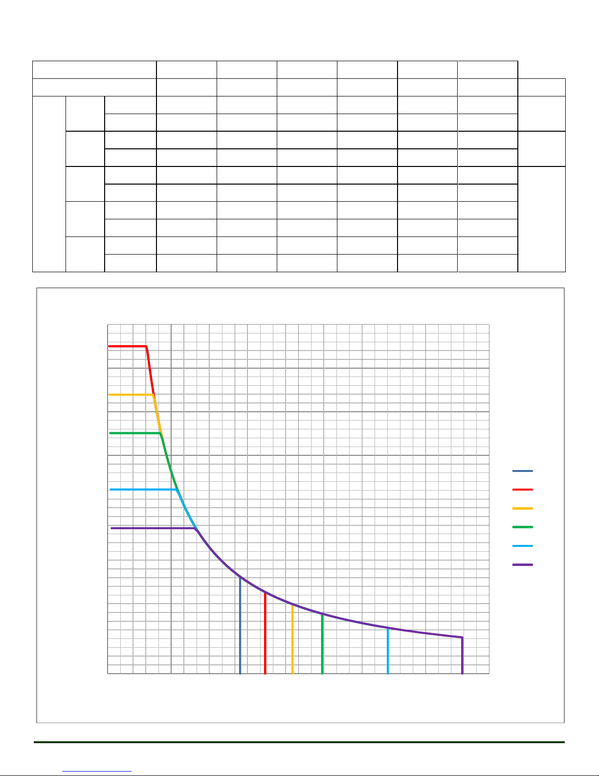
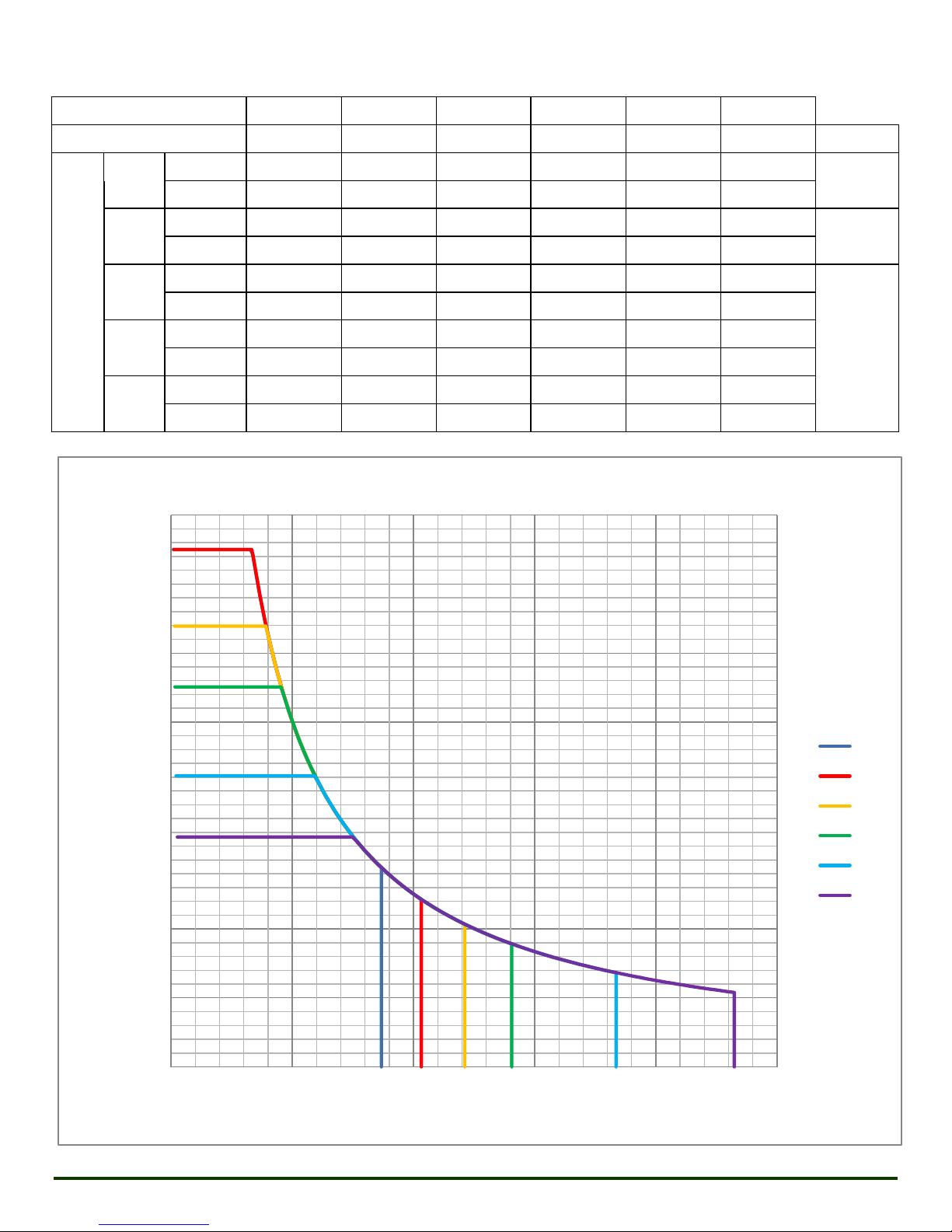
The MSI Hybrid™ Well Service Pump is rated for pumping fluids up to 15,000 PSI or at flow rates up to 929
GPM. With different materials it can handle many fluid types, including abrasive and corrosive fluids. Seals
are also available for low temperature and CO2applications.
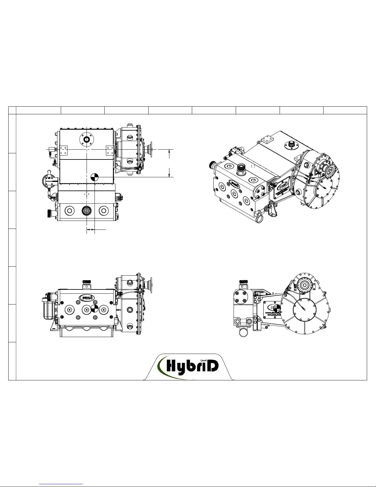
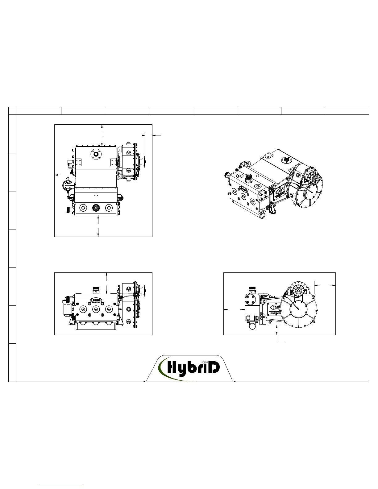
2.2 Pump Specifications
The MSI Hybrid™ Well Service Pump is a full 6" stroke, single acting reciprocating plunger pump available in
600 bhp triplex; and 1000 bhp or 1300 bhp quintuplex models. All models are rated for a 106,029 pound rod
load.
The Xtreme Service™ fluid end includes a patented system of tension bolts that reduces the stresses in the fluid
end. This reduction in stress increases the life expectancy of the fluid end thus substantially lessening costs
associated with replacing cracked fluid ends. The fluid end is machined from a one-piece, high-strength, steel
or stainless steel forging.
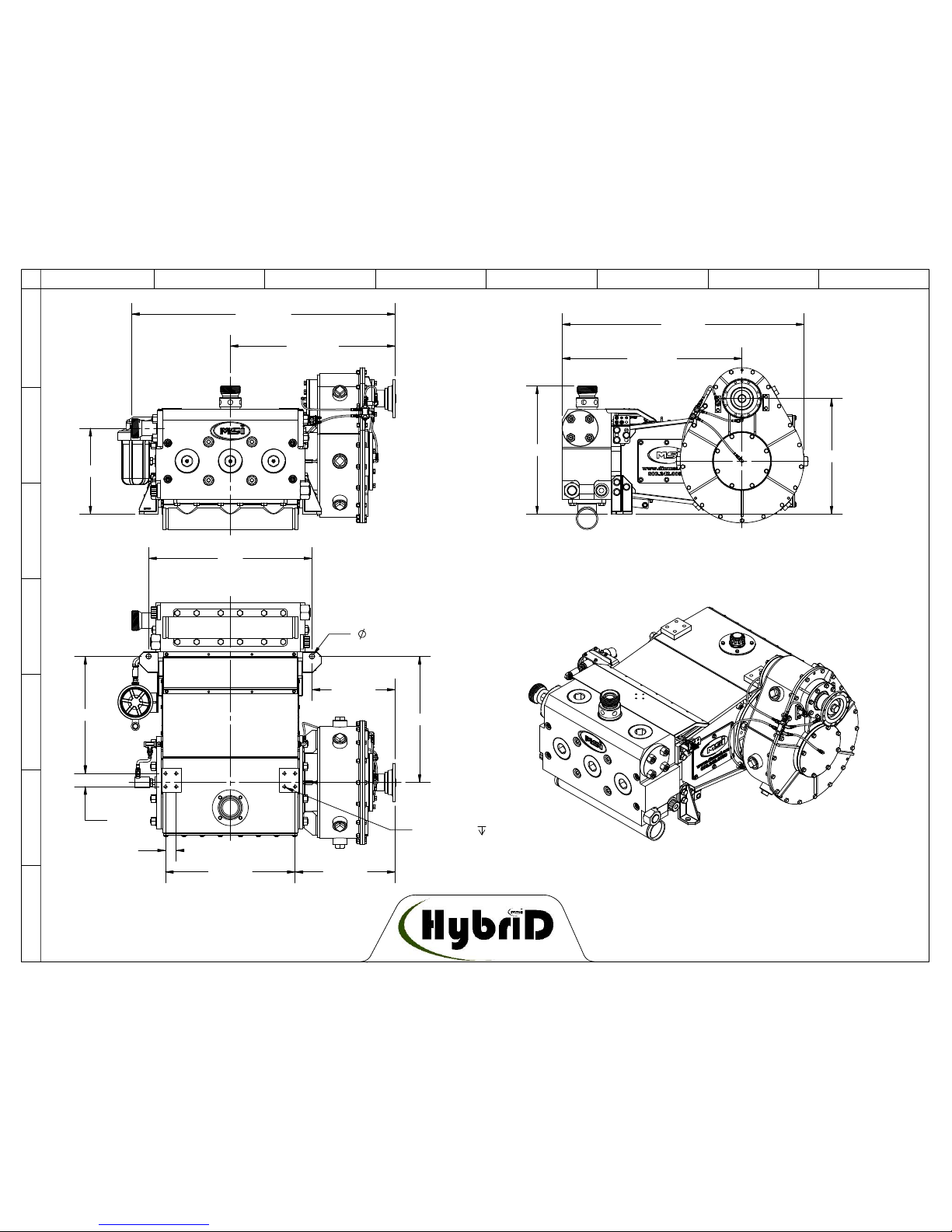
The MSI Hybrid™ Well Service Pump is equipped with a fluid end, power end, and a choice of gear reducers,
both with a 4.61:1 ratio. The standard gear reducer has a 13.00" center distance and a version is available with
a 16.50" center distance for driving over or under the pump. All gears are helical, precision ground and are
manufactured to AGMA #10 quality or better. The power end is a welded, high-strength steel frame that is
machined and line bored after stress relieving for accuracy.
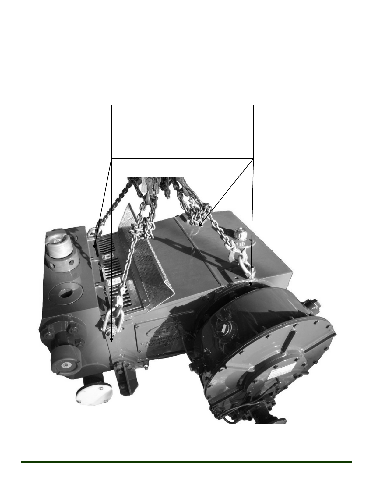
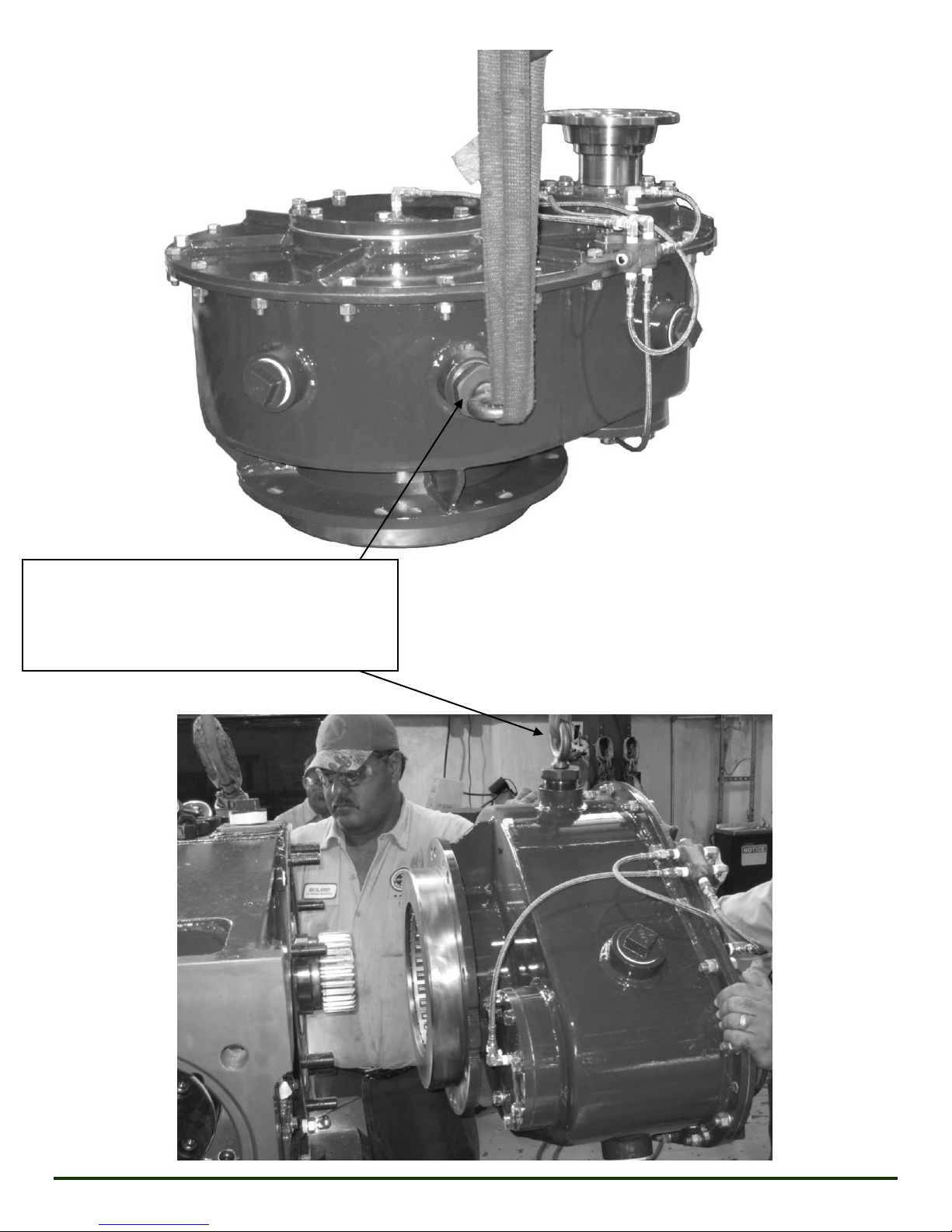
The Hybrid™ Well Service Pump is designed to mount on a skid, a well service truck, or other rigid platform.
Revision K 03/12/2019
MSI - A Division of Dixie Iron Works, Ltd. All rights reserved.
Page 2

2.3 Pump Performance
The MSI Hybrid™ Well Service Pump can be equipped with 2.75", 3.00", 3.25", 3.50", 4.00", or 4.50" diameter
fluid end plungers. There are two Xtreme Service™ fluid end sizes, one accommodates plunger sizes 2.75" –
3.00", and the other accommodates plunger sizes 3.25" –4.50". See following pages for performance tables and
curves.
Revision K 03/12/2019
MSI - A Division of Dixie Iron Works, Ltd. All rights reserved.
Page 3

A TIH-600 will produce the following capacities:
PLUNGER
2.75
3.00
3.25
3.50
4.00
4.50
GAL/REV
0.46
0.55
0.65
0.75
0.98
1.24
BHP
RPM
50
GPM
23
28
32
37
49
62
268
PSI
15,000
15,000
12,781
11,020
8,438
6,667
100
GPM
46
55
65
75
98
124
536
PSI
15,000
15,000
12,781
11,020
8,438
6,667
200
GPM
93
110
129
150
196
248
600
PSI
9,999
8,402
7,159
6,173
4,726
3,734
300
GPM
139
165
194
225
294
372
PSI
6,666
5,601
4,773
4,115
3,151
2,489
450
GPM
208
248
291
337
441
558
PSI
4,444
3,734
3,182
2,744
2,100
1,660
0
2,000
4,000
6,000
8,000
10,000
12,000
14,000
16,000
0 100 200 300 400 500 600
Pressure (PSI)
Flow Rate (GPM)
TIH-600 BHP
2.75
3.00
3.25
3.50
4.00
4.50
Revision K 03/12/2019
MSI - A Division of Dixie Iron Works, Ltd. All rights reserved.
Page 4

A QIH-1000 will produce the following capacities:
PLUNGER
2.75
3.00
3.25
3.50
4.00
4.50
GAL/REV
0.77
0.92
1.08
1.25
1.63
2.07
BHP
RPM
50
GPM
39
46
54
62
82
103
446
PSI
15,000
15,000
12,781
11,020
8,438
6,667
100
GPM
77
92
108
125
163
207
893
PSI
15,000
15,000
12,781
11,020
8,438
6,667
200
GPM
154
184
215
250
326
413
1,000
PSI
9,999
8,402
7,159
6,173
4,726
3,734
300
GPM
231
275
323
375
490
620
PSI
6,666
5,601
4,773
4,115
3,151
2,489
450
GPM
347
413
485
562
734
929
PSI
4,444
3,734
3,182
2,744
2,100
1,660
0
2,000
4,000
6,000
8,000
10,000
12,000
14,000
16,000
0 200 400 600 800 1000
Pressure (PSI)
Flow Rate (GPM)
QIH-1000 BHP
2.75
3.00
3.25
3.50
4.00
4.50
Revision K 03/12/2019
MSI - A Division of Dixie Iron Works, Ltd. All rights reserved.
Page 5

A QIH-1300 will produce the following capacities:
PLUNGER
2.75
3.00
3.25
3.50
4.00
4.50
GAL/REV
0.77
0.92
1.08
1.25
1.63
2.07
BHP
RPM
50
GPM
39
46
54
62
82
103
446
PSI
15,000
15,000
12,781
11,020
8,438
6,667
100
GPM
77
92
108
125
163
207
893
PSI
15,000
15,000
12,781
11,020
8,438
6,667
200
GPM
154
184
215
250
326
413
1,300
PSI
12,999
10,923
9,307
8,025
6,144
4,854
300
GPM
231
275
323
375
490
620
PSI
8,666
7,282
6,205
5,350
4,096
3,236
450
GPM
347
413
485
562
734
929
PSI
5,777
4,854
4,136
3,567
2,731
2,158
0
2,000
4,000
6,000
8,000
10,000
12,000
14,000
16,000
0 200 400 600 800 1000
Pressure (PSI)
Flow Rate (GPM)
QIH-1300 BHP
2.75
3.00
3.25
3.50
4.00
4.50
Revision K 03/12/2019
MSI - A Division of Dixie Iron Works, Ltd. All rights reserved.
Page 6

SECTION 3 PRESERVATION
3.1 Preservation Considerations
Steel will rust if proper measures are not taken. The MSI Hybrid™ Well Service Pump is packaged and
shipped with several preservation precautions in place. It is important to note the following suggestions for
long-term storage or for protecting the pump between well service operations, especially if the pump is to be
idle between well service jobs or in storage for long periods of time.
3.2 Preservation for Shipping
Every MSI pump undergoes factory acceptance testing (FAT) at the MSI test facility before it is cleaned,
painted, and preserved for shipping. This FAT procedure involves operating the pump through a full range of
horsepower and pressure. During the FAT, water is used as the pumping medium. Once the test is completed,
the water residue in the fluid end is removed, and all fluid end internal parts are generously misted with water
displacing protective lubricant. Following the FAT, the insides of the gear reducer and power end are fully
coated with high grade lubrication oil. After final painting, the pump is shrink-wrapped to create a vapor
barrier. Desiccant packets are placed within the shrink wrap to absorb internal moisture. If the pump is to be
shipped overseas, it is also placed within a completely enclosed wooden crate which has been properly prepared
for overseas shipments.
3.3 Preservation for Storage
If your new MSI Hybrid™ Well Service Pump, as packaged from MSI, will be in storage for longer than one
month, then the following preservation measures should be taken:
After taking delivery of the pump, remove the top of the shipping crate for pump inspection; be careful to
not damage the crate. Examine the pump and vapor barrier for any signs of condensation, this could
indicate a broken seal or depleted desiccant. Remove and dry out any water found inside the packaging and
replace the desiccant if necessary. Reseal the moisture barrier using sheet plastic and duct tape then reinstall
the crate top. These steps must be performed if the pump was ocean freighted. If the pump will be stored
in a tropical climate MSI recommends the above inspections are performed at least every 3 months. Always
store the pump indoors to keep the unit protected from moisture.
Revision K 03/12/2019
MSI - A Division of Dixie Iron Works, Ltd. All rights reserved.
Page 7

Prepping the pump for operation after removing from long term storage (> 3 months):
Prior to attempting to operate a pump that has been in storage for greater than 3 months, it is recommended
the following sealing elements at the least be replaced:
Discharge flange lip seals
Suction cover, discharge cover, and gauge connection lip seals
All packing header and pressure rings
Stuffing box adapter seals
The following sealing elements shall at the very least be removed and carefully inspected for damage and
replaced as required:
Packing nut o-rings
Packing nut wiper ring
Suction manifold o-rings
Refer to Section 6 for start-up procedures.
If your pump has been in service:
For the Fluid End:
If the unit has been in service and will be stored for more than a couple of weeks, remove the valve covers
from the fluid end and blow all moisture out with dry, compressed air. Wear proper protective gear while
blowing out moisture to prevent contact with the well service fluid. Generously mist the inside of the fluid
end with a suitable lubricant to displace trapped water and create a protective film on the metallic
components. Replace the valve covers. Seal off all inlets and outlets with plastic sheet and tape or with
mechanical blind seals. CAUTION: Well service fluid will be trapped between the inlet and outlet valves
and will spill out when removing the suction valve covers. Preparation for spillage is important for safety
and environmental reasons. A catch pan and appropriate absorbent materials will be needed.
For the Power End:
If the pump has been in service, moisture from humidity can enter through the oil cap/breather and will
accumulate at the inside bottom of the power end. If this occurs, remove the back access panel (See Section
11.4) and wipe out the accumulated moisture with a suitable absorbent. Do not use granulated absorbents
inside the pump. Replace the back cover after moisture has been removed. To further protect the pump
from humidity while in storage, especially when stored near large bodies of water or in areas of high
humidity, use duct tape to seal off the oil cap/breather. Sealing in this manner will be more effective if the
air inside the pump is warmer than outside air prior to sealing the oil cap/breather. If the cap on the
lubricating oil reservoir is a breather style cap, it should also be sealed at this time.
Outdoor Storage:
If the used pump is to be stored outdoors, it should be placed in a covered location that will protect the
pump from direct exposure to moisture and sunlight. If a covering is not available, the pump should be
covered and tied with a heavy duty tarp.
Revision K 03/12/2019
MSI - A Division of Dixie Iron Works, Ltd. All rights reserved.
Page 8

3.4 Preservation Between Jobs
The internal fluid end components can oxidize and corrode after exposure to well service fluid, especially if the
well service fluid contained water, brine, or acids. If possible, remove the valve covers and use dry,
compressed air to blow out moisture from the fluid end. After removing the valve covers, generously mist the
inside with a suitable lubricating oil to displace moisture and create a protective film on the metallic
components. Wear proper protection when working with compressed air on the inside of the fluid end.
Covering all exposed discharge or suction openings will help in further preventing ingress of moisture to the
pump.
Revision K 03/12/2019
MSI - A Division of Dixie Iron Works, Ltd. All rights reserved.
Page 9

SECTION 4 INSTALLATION
4.1 Pump Dimensions, CG, Lifting Points, and Mounting Requirements
See drawings and photographs on following pages.
Revision K 03/12/2019
MSI - A Division of Dixie Iron Works, Ltd. All rights reserved.
Page 10

SINGLE DIMENSIONS: TRIPLEX OR QUINTUPLEX
DUAL DIMESIONS: TRIPLEX
QUINTUPLEX
76 1/8"
45 15/16
34 5/16"
54 13/16"
17 13/16"
E
D
C
A
12345678
G
F
B
PUMPDIMENSIONS
CRANKSHAFT
C
L
C
L
CENTER CYLINDER
3/4"-10 UNC 3/4"
TYP
24 3/8" 26 1/4"
1"
52"
34"
19 7/8"
17 1/4"
44 1/4"
27"
2 1/4"
2 3/4"
20 3/4"
23 3/8"
24"
26 5/8"
37 7/16"
50 3/8"
Revision K 03/12/2019
MSI - A Division of Dixie Iron Works, Ltd. All rights reserved.
Page 11

14"
FROM CRANKSHAFT C
L
5" FROM CENTER CYLINDER C
L
CG IS APPROXIMATE FOR COMMON CONFIGURATIONS FOR
EITHER THE TRIPLEX OR QUINTUPLEX PUMP, DIFFERENT GEAR
POSITIONS AND PLUNGER SIZES WILL MOVE THE CG SLIGHTLY
F
E
D
C
A
12345678
G
B
PUMPCENTEROFGRAVITY
Revision K 03/12/2019
MSI - A Division of Dixie Iron Works, Ltd. All rights reserved.
Page 12

The pump CG are shown in the previous drawings. Use only properly rated lifting harnesses for installation,
removal, and maintenance of the MSI Hybrid™ Well Service Pump. Please note that the weights listed on the
following pages are average weights based on typical pump configurations. Please contact MSI for
configuration-specific weights.
Safe lifting methods are shown below:
To lift complete pump, use rated swivel
lifting eyes threaded into the 3/4-10 UNC
holes at locations shown.
TIH-600 Pump Total Wt ~ 4700 LBS
QIH-1000/1300 Pump Total Wt ~ 7500 LBS
Revision K 03/12/2019
MSI - A Division of Dixie Iron Works, Ltd. All rights reserved.
Page 13

Use 2" MNPT bull plug tapped to accept rated
lifting eyes.
TIH-600 Gear Reducer Wt ~ 900 LBS
QIH-1000/1300 Gear Reducer Wt ~ 1200 LBS
Revision K 03/12/2019
MSI - A Division of Dixie Iron Works, Ltd. All rights reserved.
Page 14

Use MSI lifting sub LSA0001.
TIH-600 Fluid End Wt ~ 1600 LBS
QIH-1000/1300 Fluid End Wt ~ 2500 LBS
Revision K 03/12/2019
MSI - A Division of Dixie Iron Works, Ltd. All rights reserved.
Page 15

4.2 Maintenance Space Requirements
When determining the design of the pump installation, consideration must be given to the access needs for
general maintenance of the pump. Working space is needed to replace consumables such as valves, fluid end
plungers, and packing. Space is also needed to inspect and adjust the pinion bearing pre-load of the gear
reducer (see Section 10.2). Consideration should also be given to major repairs that must be accomplished at
the factory, and the pump package should be designed to allow for removal of the pump.
MSI has provided a combination weather cover and safety guard for the plunger access ports. The cover
additionally serves to store tools specific to the MSI Hybrid™ Well Service Pump. It is the responsibility of the
packager to design the unit in such a way that this equipment is intact and functional.
Maintenance access suggestions are shown on following page:
Revision K 03/12/2019
MSI - A Division of Dixie Iron Works, Ltd. All rights reserved.
Page 16

*15"
15"
15"
15"
*
5"
15"*
7"
15"
THESE ARE SUGGESTED MINIMUMS FOR MAINTENANCE SPACE
FOR THE TRIPLEX OR QUINTUPLEX PUMP. WORKING SPACES
DENOTED BY * SHOULD BE PROVIDED IN ANY CONFIGURATION
FOR ACCESS TO COMMONLY REPLACED ITEMS SUCH AS
VALVES, VALVE SEATS, PACKING, AND SEALS.
8
G
F
E
D
C
A
1234567
B
MAINTENANCESPACE
Revision K 03/12/2019
MSI - A Division of Dixie Iron Works, Ltd. All rights reserved.
Page 17
This manual suits for next models
1
Table of contents
Other MSI Water Pump manuals
Popular Water Pump manuals by other brands

Gardner Denver
Gardner Denver Elmo Rietschle twister S Series operating instructions

ARAG
ARAG 462F4501 Installation, use and maintenance

MULTIQUIP
MULTIQUIP QP303B Operation manual

SPI
SPI VALVES SP160 Series Installation operation & maintenance

Grundfos
Grundfos AP51 Series Installation and operating instructions

Crane
Crane BARNES BAF-E3 installation manual

Meec tools
Meec tools 731-108 User instructions

sauermann
sauermann Si-30 Detect + manual

Clarke
Clarke PSV6A Operation & maintenance instructions

Waterous
Waterous CX Series OVERHAUL INSTRUCTIONS

Grundfos
Grundfos UPM3 Installation and operating instructions

Grundfos
Grundfos MAGNA1 C Installation and operating instructions