MSI TI-600 User manual


Table of Contents
Location
Title
Section 1
General
1.00
General Description
1.10
Recommended Shipping & Storage
1.20
Drawings-Complete Pump Assembly
1.30
Drawings-Pump Assembly-Overall Dimensions
1.40
Drawing-Dual Pump Configuration-Overall Dimensions
1.50
Drawings-Gear Reducer Installation Positions
1.60
600 HP Pump Performance Data
1.70
1000 HP Pump Performance Data
Section 2
Initial Inspection & Break-in
2.00
Operation & Maintenance
2.10
Initial Inspection
2.20
Seating Valves
2.30
Start-up & Testing Considerations
2.40
Pump Unit Testing Procedure
2.50
Warm-up Prior to Rotating Pump
Section 3
Preventative Maintenance
3.00
Scheduled Maintenance
3.10
First 100 Hours of New Pump Operation
3.20
Daily Preventative Maintenance
3.30
Weekly Preventative Maintenance
3.40
Every 100 Hours Preventative Maintenance
3.50
Every 250 Hours Preventative Maintenance
3.60
Yearly or as Required Preventative Maintenance
3.70
Inspection of Bearings and Gears

Section 4
Lubrication System
4.00
Drawing- Schematic on Lube System
4.10
Drawing- Power Frame Lube Lines-Dual Lube Pipe
4.20
Drawing- Gear Reducer Lube Lines
4.30
Recommended Lubrication Specifications
4.40
General Service Lube Oils for Power Frame
4.50
Cold Temperature Service Lube Oils for Power Frame
4.60
High Temperature Service Lube Oils for Power Frame
4.70
Lubrication Supply System
4.80
Lube Pump
4.90
Oil Reservoir
4.100
Lube System Suction Piping
4.110
Lube System Pressure Lines and Oil Filter
4.120
Lube System Relief Valve and Relief Return Line
4.130
Lube Drain Lines (from Plunger Pump to Reservoir)
4.140
Optional Lube System Equipment
4.150
Recommended Plunger Lubrication Specifications
Section 5
Power End
5.00
Power Frame Repair Procedures
5.10
Drawings-Power Frame Assembly-Reference Drawings
5.20
Drawing-Power Frame Assembly-Section View
5.30
Removing the Crankshaft, Connecting Rods, & Crossheads
5.40
Drawing- Power Frame Lube Lines-Dual Lube Pipe
5.50
Drawing- Power Frame Crank Rotation
Section 6
Fluid End Repair Procedures
6.00
Fluid End Repair Procedures
6.10
Drawings-Fluid End Assembly - 2.75"-3.00"
6.20
Drawings- Fluid End Assembly - 3.25"-4.50"
6.30
Packing Assembly

6.40
Removing the Plungers and Packing
6.50
Removing the Valve Seats
6.60
Removing the Discharge Flanges
6.70
Removing the Suction Manifold
6.80
Removing the Fluid End
Section 7
Gear Reducer Repair Procedures
7.00
Gear Reducer Repair Procedures
7.10
Removing & Disassembling the Gear Reducer
7.20
Drawings-Gear Reducer-Exploded View
Section 8
Supercharging
8.00
Supercharging the Pump Intake (Suction Manifold)
8.10
Supercharging Operational Parameters
8.20
Supercharge Pressure Gauge
8.30
Centrifugal Supercharge Pump/Mixing Pump
8.40
Primary Suction Piping & Hoses
8.50
Secondary Suction Piping & Hoses
8.60
Suction Pulsation Dampener
Section 9
Appendix
9.00
Useful Formulas
9.10
Conversion Factors
9.20
Recommended Torque

1.00 General Description
The MSI TI-600 is a 600 horsepower triplex pump. The MSI QI-1000 is a 1000 horsepower quintuplex
pump. These pumps are suited for oilfield service applications.
These pumps are composed of three main components: Power Frame, Fluid End, and a Gear Reducer.
The pump is designed for sixteen left and right-hand configurations of the Gear Reducer without
removing the crankshaft.
The Power Frame is composed of the crankshaft, the crossheads, the crosshead guides, connecting rods,
and diaphragm seal housing in a high-strength steel frame. The Power Frame should be mounted to a
skid or other rigid platform before operating (see 1.30).
The Fluid End is composed of valves, springs, intake manifold, discharge flanges and various access
covers. The Fluid End is machined from a one-piece, high-strength steel forging. One Fluid End will
accept plunger sizes from 2.75 to 3.00 inches and the other plungers 3.25 to 4.50 inches in diameter.
The Fluid End is bolted to the Power Frame with high-strength tension-indicating bolts.
The Gear Reducer houses a helical AGMA #10 precision ground pinion and gear providing a reduction
ratio of 4.61:1.
1.10 Recommended Shipping and Storage
Every MSI pump is fully factory acceptance tested (FAT) at MSI before it is cleaned, painted, and
preserved for shipping. This FAT procedure runs the pump through the full range of horsepower and
pressure. During the FAT, water is used as the pumping medium. Once the test is completed, the water
residue in the fluid end is removed, and all fluid end internal parts are generously misted with water
displacing protective lubricant. Following the FAT, the insides of the gear reducer and power end are
fully coated with high grade lubrication oil. After final painting, the pump is shrink-wrapped to
prevent excessive exposure to humidity and rain. Desiccant packets are placed within the shrink wrap
to absorb internal moisture. If the pump is to be shipped overseas, it is also placed within a completely
enclosed wooden crate which has been properly prepared for overseas shipments.
If your new MSI Well Service Pump, as packaged from MSI, will be in storage for longer than one
month, then the following preservation measures should be taken:
Inspect the unit.
Look for any condensation or accumulation of water inside the shrink wrapping which could indicate a
broken seal or depleted desiccant. Remove and dry out any water found inside the packaging and
replace the desiccant if necessary. Reseal the moisture barrier using sheet plastic and duct tape.
Keeping the unit out of moisture or away from salt spray is helpful.
If your pump has been in service:
For the Fluid End:
If the unit has been in service and will be stored for more than a couple of weeks, remove the cover

nuts, valve stop, springs and valve covers from the fluid end and blow all moisture out. Wear proper
protective gear while blowing out moisture to prevent contact with the well service fluid. Generously
mist the inside of the fluid end with a suitable lubricant to displace trapped water and create a
protective film on the metallic components. Replace the valve covers, springs, valve stop, and cover
nuts. Seal off all inlet and outlets with mechanical blind seals. CAUTION: Well service fluid will be
trapped between the inlet and outlet valves and will spill out when removing the suction valve covers.
Preparation for spillage is important for safety and environmental reasons. A catch pan and appropriate
absorbent materials will be needed.
For the Power End:
If the pump has been in service, moisture from humidity can enter through the oil cap/breather and will
accumulate in the inside bottom of the power end. If this occurs, remove the back access panel and
wipe out the accumulated moisture with a suitable absorbent. Do not use granulated absorbents inside
the pump. Replace the back cover after moisture has been removed. To further protect the pump from
humidity while in storage, especially when stored near large bodies of water or in areas of high
humidity, use duct tape to seal off the oil cap/breather. Sealing in this manner will be more effective if
the air inside the pump is warmer than outside air prior to sealing the oil cap/breather. If the cap on the
lubricating oil reservoir is a breather style cap, it should also be sealed at this time.
Outdoor Storage:
If the used pump is to be stored outdoors, it should be placed in a covered location that will protect the
pump from direct exposure to moisture and sunlight. If a covering is not available, the pump should be
covered and tied with a heavy duty tarp.
Preservation Between Jobs:
The internal fluid end components can oxidize and corrode after exposure to well service fluid,
especially if the well service fluid contained water, brine, or acids. If possible, remove the valve covers
and use compressed air to blow out moisture from the fluid end (see CAUTION statement above).
After removing the valve covers, generously mist the inside with a suitable lubricating oil to displace
moisture and create a protective film on the metallic components. Wear proper protection when
working with compressed air on the inside of the fluid end. Covering all exposed discharge or suction
openings will help in further preventing ingress of moisture to the pump.

1.20 Drawings - Pump Assembly Overall Dimensions (All Plunger Sizes)
TI-600 (TRIPLEX)

QI-1000 (QUINTUPLEX)
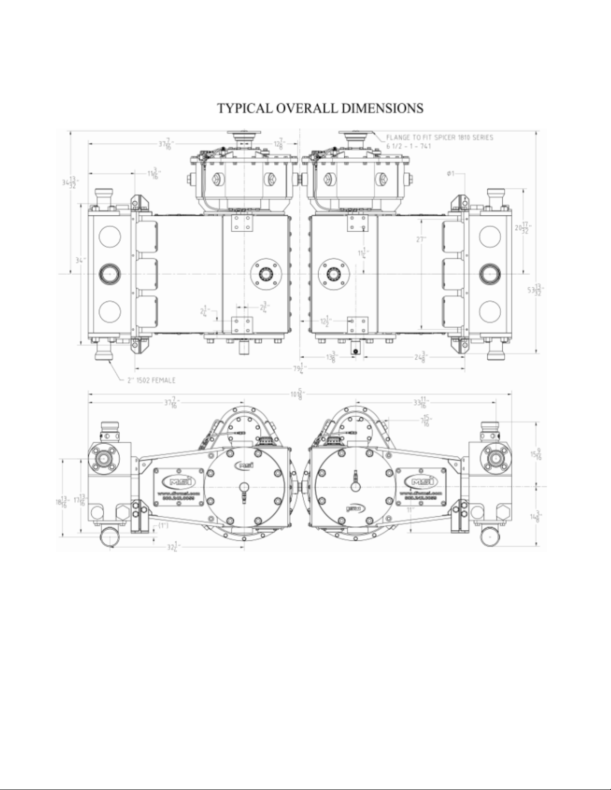
1.30 Dual Pump Assembly Overall Dimensions
1.30.1 600 HP Dual Pump Assembly Overall Dimensions

1.30.2 1000 HP Dual Pump Assembly Overall Dimensions

1.50 Drawings - Gear Reducer Installation Positions
1.50.1 Gear Reducer Position-Left Hand

1.50.2 Gear Reducer Position Right Hand

1.60 600 HP Pump Performance Data
PLUNGER
2.75
3.00
3.25
3.50
4.00
4.50
BHP
GAL/REV
0.46
0.55
0.65
0.75
0.98
1.24
RPM
50
GPM
23
28
32
37
49
62
268
PSI
15,000
15,000
11,020
11,020
8,438
6,667
100
GPM
46
55
65
75
98
124
536
PSI
15,000
15,000
11,020
11,020
8,438
6,667
200
GPM
93
110
129
150
196
248
600
PSI
9,999
8,402
7,159
6,173
4,726
3,734
300
GPM
139
165
194
225
294
372
PSI
6,666
5,601
4,773
4,115
3,151
2,489
450
GPM
208
248
291
337
441
558
PSI
4,444
3,734
3,182
2,744
2,100
1,660

1.70 1000 HP Pump Performance Data
PLUNGER
2.75
3.00
3.25
3.50
4.00
4.50
BHP
GAL/REV
0.77
0.92
1.08
1.25
1.63
2.07
RPM
50
GPM
39
46
54
62
82
103
446
PSI
15,000
15,000
11,020
11,020
8,438
6,667
100
GPM
77
92
108
125
163
207
893
PSI
15,000
15,000
11,020
11,020
8,438
6,667
200
GPM
154
184
215
250
326
413
1,000
PSI
9,999
8,402
7,159
6,173
4,726
3,734
300
GPM
231
275
323
375
490
620
PSI
6,666
5,601
4,773
4,115
3,151
2,489
450
GPM
347
413
485
562
734
929
PSI
4,444
3,734
3,182
2,744
2,100
1,660
2.00 Operation and Maintenance
When determining the design of the pump installation, clearance is recommended for inlet and outlet
connections as well as providing for a pressure relief device for the discharge line. A pressure relief device is
required for all applications of this pump. Failure to implement a pressure relieving device may result
in significant damage to the pump and attached piping, serious injury or death of personnel, and will
void the pump warranty. Please read the following concerning pressure relief devices and the allowable
mounting locations.
Spring loaded ball and seat relief valves:
Pressure relief devices of this type rely on a ball and seat interface to create a seal. Force is exerted on the ball,
typically with springs, to balance a predetermined line pressure. This type of pressure relief device is not
designed for full opening once relief pressure has been achieved, in other words, a ball and seat relief valve is
not a full-bore volume relief device and sufficient fluid volume will cause line pressure to continue to rise
due to the small flow area available. As the line pressure exceeds the set pressure of the relief valve, the ball
temporarily separates from the seat thus allowing excess pressure to flow through. Once line pressure has
dropped below the set pressure of the relief valve, the ball will re-seat. Due to the small volume relief capacity
of these types of pressure relief devices it is acceptable to install them on a fluid end gauge connection(s).
While not intended as a full-bore volume relief device connection point, the gauge connection will provide a
sufficient conduit for a ball and seat type relief valve. Valves or other closure devices shall not be installed
between the pop-off valve and the fluid end. Always follow the manufacturer’s recommendations for the
installation, use, and maintenance of the relief valve.
Full bore (pop-off) relief valves:
Full-bore relief valves are designed to allow full bore dissipation of pressure by relieving large volumes of
fluid. As such, these relief devices must not be installed on the fluid end gauge connection(s). The pop-off
valve should be installed as close to the fluid end as possible and in the discharge piping circuit at either the
blind side of the fluid end (for single side discharge) or connected to a TEE fitting on the discharge side of the
fluid end. Valves or other closure devices shall not be installed between the pop-off valve and the fluid
end. Always follow the manufacturer’s recommendations for the installation, use, and maintenance of the
pop-off valve.
Below are the maximum relief set pressures based on plunger diameter.
Plunger Diameter
Relief Device Maximum Set Pressure
2.75”
15,000 psig
3.00”
15,000 psig
3.25”
11,020 psig
3.50”
11,020 psig
4.00”
8,438 psig
4.50”
6,667 psig
2.10 Initial Inspection
a) Check to see that all moving parts are clean and free of any shipping debris
b) Check to see that pump is securely bolted to mounting platform
c) Check to see that driveline is securely fastened to the pump’s Gear Reducer input shaft with
adequate slip (1 inch minimum) in the slip joint
d) Check the Fluid End bolts. Each has a mechanical indicator in the face and should be between
90 and 95 on the dial. Tighten as necessary, but do not surpass 95 on the dial. If the indicator is
not working return it to MSI for immediate replacement. Note: In order to achieve the
necessary preload without damaging the bolt, DOW CORNING G-n Metal Assembly
Paste must be used.
e) Make sure the Power Frame has correct oil in its reservoir (Section 4)
f) Make sure the plunger lube system has proper type of packing oil or grease
g) Check to see that supercharge piping system is clean and all connections are tight
h) Check to see that adequate water is available to suction manifold for testing
i) Check to see that discharge piping connections are tight and all valves are open
j) Start the supercharge pump and flush the air from the system
2.20 Seating Valves
If the pump was delivered with valves installed, then the valves were already seated during the FAT
test. If the valve seats were replaced in the field, the following procedure must be followed to set the
valve seats:
a) The tapered valve seats must be fully seated to allow optimum flow area between the valve and
the seat. Washout may also occur between the valve and the fluid end if the valves are not fully
seated.
b) Connect a 3/4” to 1” orifice test choke to the discharge circuit and adjust it to full open. Slowly
increase discharge pressure using the test choke until a series of audible popping noises are
heard. This indicates the seats have properly set in the taper. The approximate seating pressure
for each plunger size is as follows:
Plunger Diameter
Rated Pressure
2 ¾”
14,320 PSI
3”
12,030 PSI
3¼”
8,840 PSI
3 ½”
8,840 PSI
4”
6,765 PSI
4 ½”
5,345 PSI
c) During this portion of the startup procedure, closely observe the plunger pump for any unusual
noise, vibration, fluid leaks and oil leaks. Record all pertinent information such as elapsed time,
ambient temperature, Power Frame lube oil temperature, and Power Frame lube oil pressure,
supercharge pressure, etc. After returning the engine to idle and transmission to neutral,
physically inspect the plunger pump before proceeding further.

3.00 Scheduled Maintenance
MSI recommends that all pumps have regular scheduled maintenance. Regular maintenance will help
ensure trouble-free operation.
3.10 First 100 Hours of New Pump Operation
a) Change Power Frame lube oil filters every 25 hours
b) Thoroughly clean the Power Frame lube oil suction strainer after the first 50 hours and 100
hours of operation.
c) Change the Power Frame lube oil after the first 100 hours of operation and clean the lube oil
reservoir.
3.20 Daily Preventative Maintenance
a) Check the oil level in the Power Frame lube oil reservoir.
b) Check the oil level in the plunger lube oil reservoir.
c) Check the plunger pump for oil leaks and/or fluid leaks.
d) Check the Power Frame lube oil system for leaks.
e) Check the plunger lube system for leaks.
f) Check the supercharge piping for leaks.
g) Check the Fluid End bolts. Each has a mechanical indicator in the face and should read
between 90 and 95 on the dial. Tighten as necessary, but do not exceed 95 on the dial. If the
indicator is not working return it to MSI for immediate replacement. Note: In order to achieve
the necessary preload without damaging the bolt, use DOW CORNING G-n Metal Assembly
Paste as a thread lubricant.
3.30 Weekly Preventative Maintenance
a) Check all items on “daily” list.
b) Check all valves, inserts, valve seats and springs.
c) Check all discharge and suction cover seals.
d) Check suction pulsation dampener for correct pre-charge if applicable
3.40 Every 100 hours Preventative Maintenance
a) Check all items on “daily” and “weekly” lists.
b) Check all plunger pump-mounting bolts to ensure that they are tight.
c) Change Power Frame lube oil filters.
d) Check all supplies needed for routine maintenance such as o-rings, fluid seals, valves, valve
inserts, valve seats, valve springs, packing, oil seals, filter elements, etc.

3.50 Every 250 hours Preventative Maintenance
a) Check all items on “daily,” “weekly,” and “100 hours” list.
b) Change the Power Frame lube oil and refill with the proper grade of gear oil for upcoming
ambient conditions.
c) Thoroughly clean the Power Frame lube suction strainer.
d) Remove and inspect the plungers and packing assembly components.
e) Replace all packing pressure rings and header rings.
f) Clean the plunger pump’s oil breather and the Power Frame lube oil reservoir breather.
3.60 Yearly or as Required Preventative Maintenance
a) Replace worn plungers and packing brass.
b) Replace worn or corroded valve covers, suction valve stops, packing nuts, discharge flanges,
pump tools, etc.
c) Replace all discharge flange seals and suction manifold seals.
d) Replace any defective gauges and instruments.
3.70 Inspection of Bearings and Gears
a) Inspection of the gears, bearings, and journal bearings should be made every 500 hours. Look
in the oil filter for telltale clues such as flaking metal. Also check for end play on pinion shaft.
This is easily checked by placing a dial indicator on face of Spicer flange and pulling on the
Spicer flange. There should be no movement on the Spicer flange. If end play is noted see
Section 7.10 paragraph (k).
b) Remember: Pitting, spalling, and other surface defects are an indication of impending failure.
Replace as necessary.

4.00 LUBRICATION REQUIREMENTS: POWER TRAIN AND PLUNGERS
4.1 Lubrication Capacity Requirements
The MSI Well Service Pump is a dry sump, i.e., it is not intended to contain a volume of lubricating oil. A
separate lubrication oil reservoir is required with a 50 gallon minimum capacity; it should be installed below
the plunger pump power end. It is recommended that a separate reservoir be used for each well service pump
on units with multiple well service pumps. Separate reservoirs prevent contaminants in one system from
affecting both lubrication systems and well service pumps. While the MSI Well Service Pump greatly reduces
the contamination, it is still prudent for the user to take all precautions to ensure long equipment life by
keeping lubrication systems separate and clean. Fill the reservoir with 45 gallons of the proper lubricating oil
listed in Section 4.8. A valve installed at the lowest point in the tank is recommended to allow for
accumulated water to be removed.
The MSI Well Service Pump is not equipped with an internal lubrication pump. The packager must add a
lubrication pump to one of the PTOs of the prime mover. The lubrication oil pump should be rated for 20
GPM and 300 PSI and be capable of pumping 90 wt oil. One lubrication pump must be dedicated to each well
service pump.
When designing the system, it is important to locate the lubrication oil pump on a PTO on the drive train that is
engaged whenever the prime mover (i.e. diesel engine) is running and not on a PTO that rotates only when the
transmission is in gear. A properly designed system will allow for oil circulation through the MSI Well
Service Pump prior to rotating the pump drive shaft and after the pump drive shaft rotation has been stopped
when the transmission has been returned to neutral. This is recommended so that the oil will warm up prior to
putting the pump into gear. The warmed oil will flow with less resistance and will better lubricate the moving
parts. Additionally, this will allow the oil to cool the pump after the plunger pump rotation has been stopped.
It is important to mount the lubrication pump as low as possible so that the pump does not cavitate as a result
of having to lift the fluid from the reservoir. If at all possible, the pump should be mounted below the outlet of
the reservoir.
A pressure gauge shall be placed as close to the top lubrication inlet port as possible to monitor lubrication
pressure. Pressure at this location must always be kept above 40 PSI, and flow rate to the plunger pump is
recommended to be at least 12 gpm at the inlet for a quintuplex, and at least 8 gpm for a triplex. Connect the
lubrication oil inlet line to the lower lubrication inlet port on either side of the well service pump; plug the
unused lubrication pipe ports with 1/2" NPT pipe plugs. Do not exceed 450 PSI lubrication pressure at the
MSI Well Service Pump power end lubrication inlet. (This pressure limitation does not apply to the fluid end
plunger lubrication system.)

4.2 Typical Lubrication Schematic
A typical power end and gear reducer lubrication oil schematic is shown below.
ITEM #
DESCRIPTION
1
RESERVOIR, VENTED 50 GALLON MIN CAPACITY
2
SUCTION LINE, PIPE OR HOSE, 1 1/2” ID MINIMUM
3
SUCTION STRAINER, 50 GPM MIN. 300 SQ IN MIN. 40-100 MESH w/3-5 PSI RELIEF
4
CHECK VALVE, SWING, 1 1/2” ID MINIMUM
5
VACUUM GAUGE, LIQUID FILLE, 0-30” Hg
6
PUMP, GEAR TYPE, 20 GPM, 300 PSI MIN. ENGINE OR TRANSMISSION DRIVEN
7
PRESSURE LINE, PIPE OR HOSE, 3/4” ID MINIMUM
8
FILTER, 50 GPM/200 PSI MIN. 25-33 MICRON ELEMENTS, w/ 15-25 PSI RELIEF
9
PRESSURE GAUGE, LIQUID FILLED, 0-200 PSI
10
RELIEF VALVE, ADJUSTABLE, 60-200 PSI, 3/4” ID 20-25 GPM MINIMUM
11
RELIEF RETURN LINE, PIPE OR HOSE, 3/4” ID
12
POSER FRAME DRAIN LINE, PIPE OR HOSE, 3” NPT
13
GEAR REDUCER DRAIN, PIPE OR HOSE, 2”NPT
14
TEMPERATURE TRANSDUCER/ GAUGE, 0-250°F
15
OPTIONAL HEAT EXCHANGER
16
OPTIONAL OIL COOLER
This manual suits for next models
1
Table of contents
Other MSI Water Pump manuals

Popular Water Pump manuals by other brands


covetrus
covetrus ProMAX IV quick start guide

GORMAN-RUPP PUMPS
GORMAN-RUPP PUMPS PRIME-AIRE PA6B Series MAINTENANCE AND REPAIR WITH TROUBLESHOOTING

Pentair Jung Pumpen
Pentair Jung Pumpen SKS 1000 Series instruction manual

FMT Swiss AG
FMT Swiss AG PREMAxx 230 V OPERATING INSTRUCTIONS AND SAFETY NOTES

fluid-o-tech
fluid-o-tech TMFR instruction manual

Becker
Becker KVX 3.100 operating instructions