MTP MTP-1032 User manual

MTP
Instruction Manual
Voltage Tester
Model MTP-1032
MTP Instruments
www. .com information@itm.com1.800.561.8187

Table of Content
1
Features
Page 1
2
Safety warnings
Page 1
3
Instrument layout
Page 2
4
Preparation for measurement
Page 3
4.1
Auto power-on / Self diagnostic test
Page 3
4.2
Trouble shooting
Page 4
5
Handy construction
Page 4
6
Measurement
Page 5
6.1
Voltage test (double pole test)
Page 5
6.2
Phase rotation test
Page 6
6.3
Continuity test
Page 7
6.4
Pen light function
Page 7
7
Battery replacement
Page 8
8
Specifications
Page 9
9
Cleaning and storage
Page 10
10
Safety symbols
Page 10
11
Measurement category
Page 10
12
Environment
Page 11
13
Ingress protection (IP) ratings
Page 11
Introduction
www. .com information@itm.com1.800.561.8187

Congratulations on the purchase of your Voltage Tester, Model MTP-1032. Careful use
of this meter will provide years of reliable service.
1. Features
Self-diagnostic test
AC and DC voltage tests up to 600V with LED
and LCD
Polarity indication
Phase rotation test
Continuity test
Auto-power ON/OFF
Pen light for illuminating measurement points
Probe clip for adjustable spacing between probes
Probe cover protects user and probe tips
IP64
Compact design (light-weight and portable)
2. Safety Warnings
This instruction manual contains warnings and safety rules which have to be noticed
by the user to ensure safe operation of the instrument and to maintain it in safe
condition. Therefore, read through these operating instructions before using the
instrument.
WARNING is reserved for conditions and actions that are likely to cause
serious or fatal injury.
CAUTION is reserved for conditions and actions that can cause injury or
instrument damage.
It is essential that the above instructions are adhered. Failure to follow the
above instructions may cause injury, instrument damage and/or damage to
equipment under testing.
1
www. .com information@itm.com1.800.561.8187

WARNING
Never make measurement on a circuit in which the electrical potential exceeds
600V. (While the measured voltage exceeds 600V, all the voltage display LED
light up).
Do not attempt to make measurement in the presence of flammable gases, as the
use of the instrument may cause sparking, which could lead to an explosion.
Never attempt to use the instrument if its surface or your hands are wet. (Do not
use in rainfall).
Keep your hands and fingers behind the barriers during measurements.
Never unlock and open the battery case during measurements.
Verify proper operation on a known source before taking action as a result of the
indication.
Never attempt to make any measurement in any abnormal conditions, such as a
broken case or exposed metal parts are present on the instrument or test probes.
Do not make any modification to the instrument.
Extreme caution when live circuit LED flashes or lights on.
Correct indication of LEDs is only guaranteed within a temperature range of -
10ºC up to 55ºC (<85% RH)
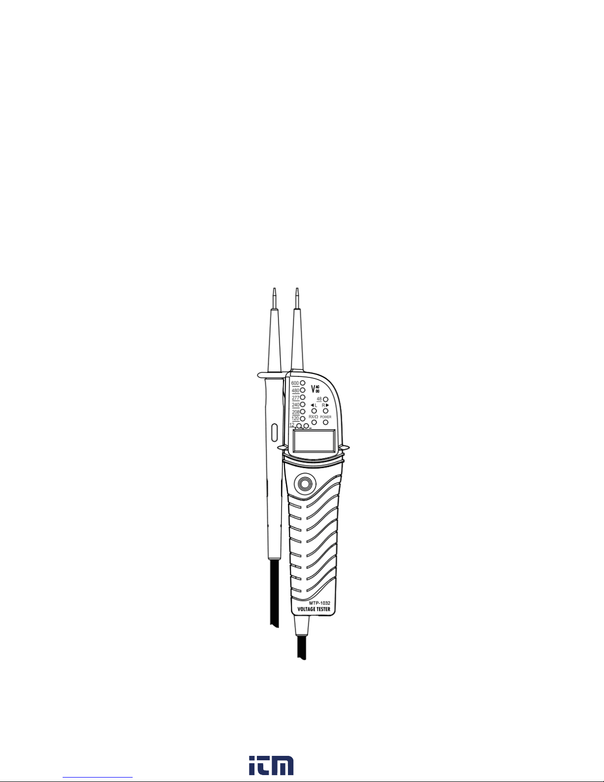
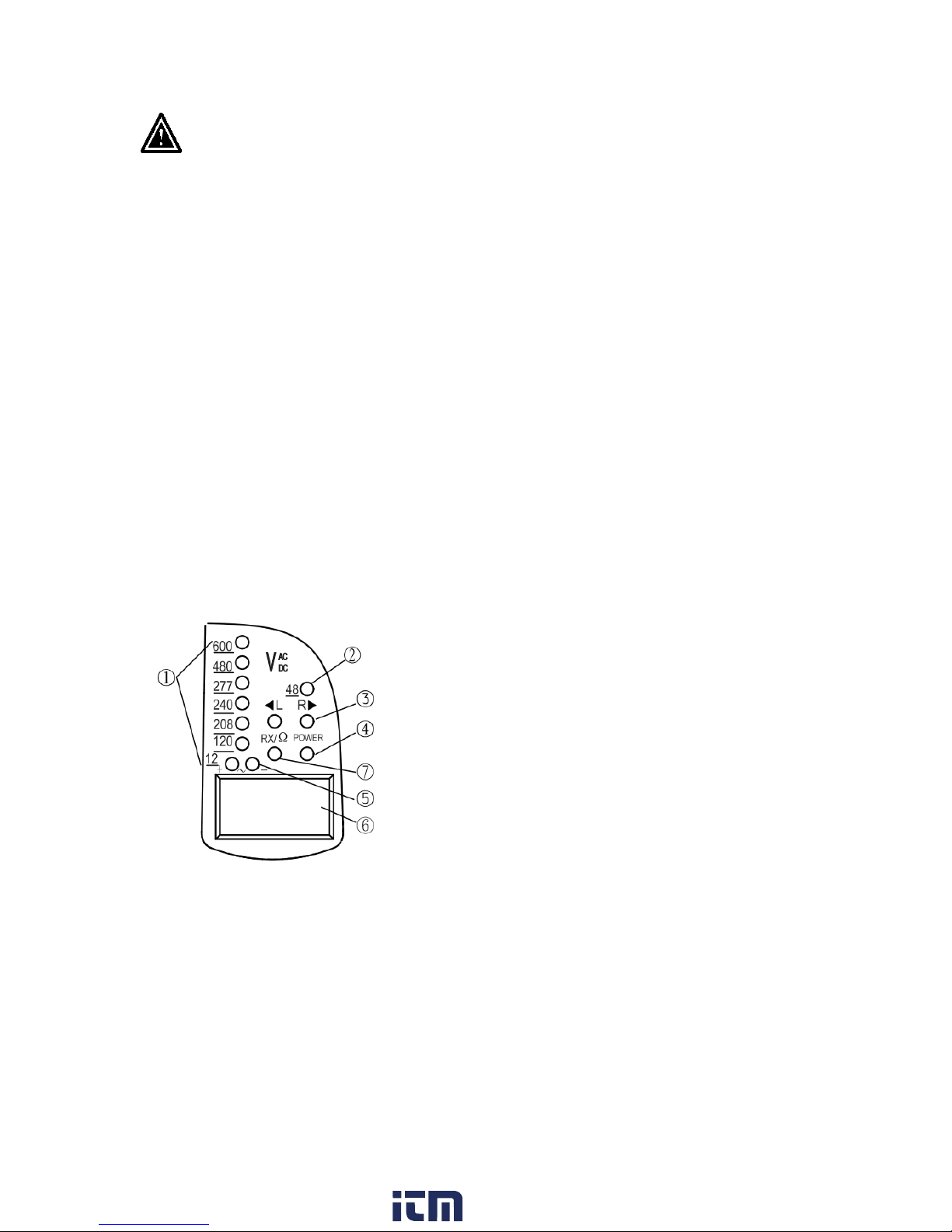
3. Instrument Layout
1) LEDs12//120/208/240/277/480/600V for voltage indication
2) LED 48V for voltage indication
3) L/R LEDs for phase rotation test
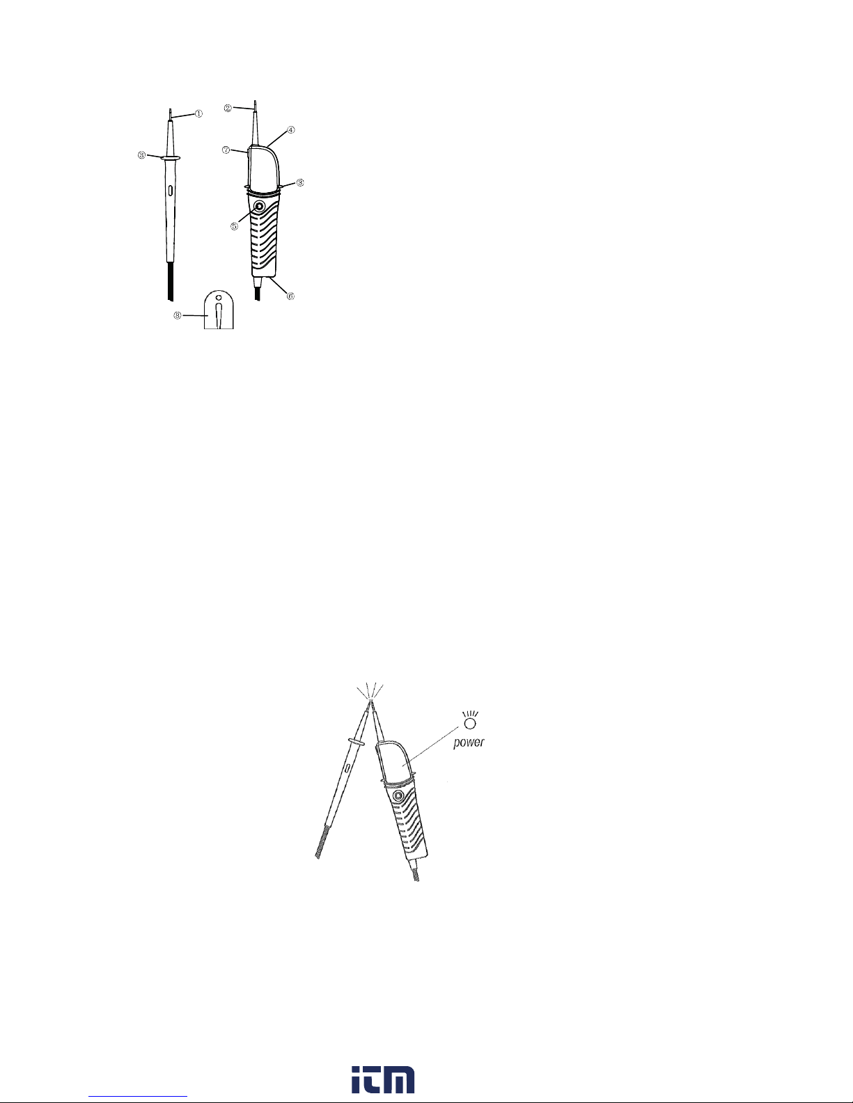
4) Power LED
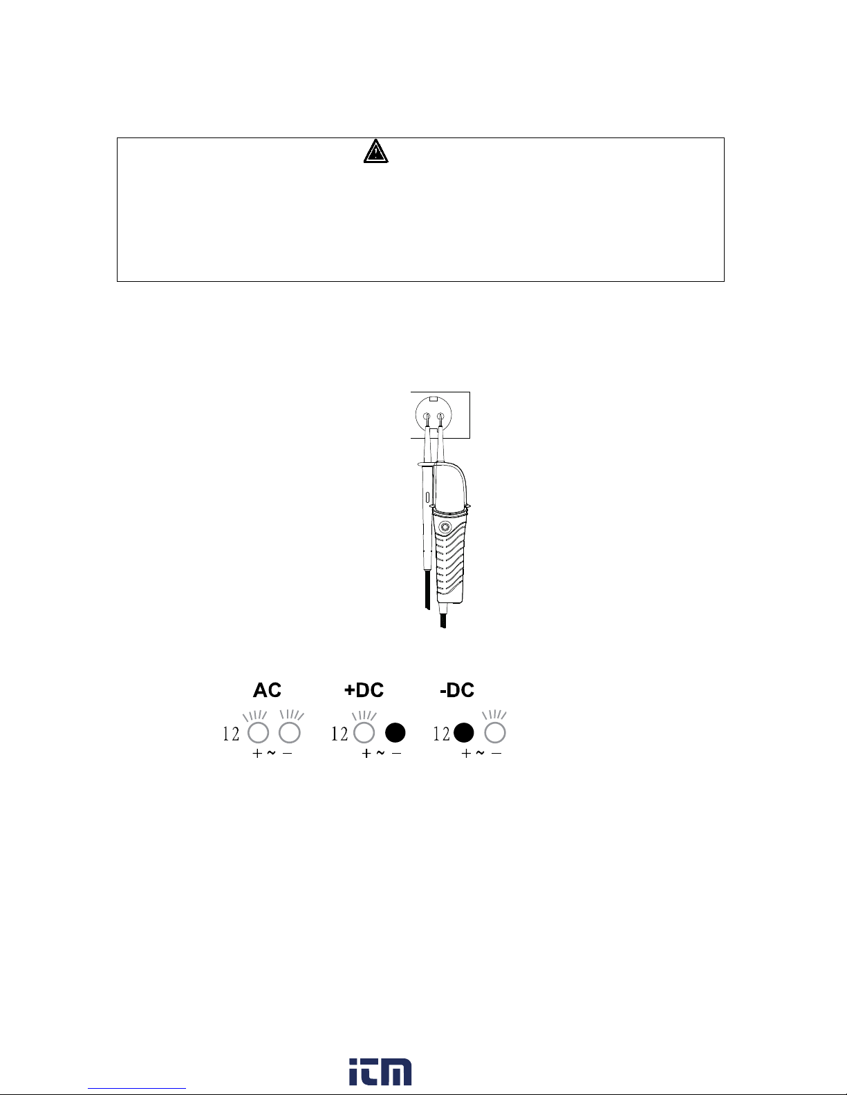
5) Polarity indication LEDs for voltage
6) LCD
7) Continuity test / live circuit LED
2
www. .com information@itm.com1.800.561.8187

1. L1 probe -
2. L2 probe + (instrument probe)
3. Barrier
4. Pen light
5. Pen light switch
6. Battery case
7. Probe clip
8. Probe protection cover
4. Preparation for Measurement
4.1 Auto Power-on / Self Diagnostic Test
Auto Power-on
Short-circuiting the probes as follows powers on the instrument automatically and
goes into a self-diagnostic test.
Instrument may power on due to the influence of static charge.
3
www. .com information@itm.com1.800.561.8187

Self-diagnostic test
WARNING
Do not use the instrument when abnormality is found at self-diagnostic test.
Battery voltage is normal when power LED is lighting up.
When the battery voltage is below 2.4 ± 0.1V, power LED flashes or goes off.
Replace batteries according to section 7.
4.2 Trouble shooting
If the following problems occur, unlock the battery case according to section 7 in this
manual, and then lock it again 5 seconds later. Then perform the self-diagnostic test
(section 4.1).
Self-diagnostic test cannot be performed before/after use of the instrument.
Automatic power-off does not operate.
5. Handy Construction
With the L1 probe on the probe clip, user can change the spacing between probes
with one hand.
4
www. .com information@itm.com1.800.561.8187

6. Measurement
WARNING
Please refer to section 2 of this manual (Safety Warnings)
Self-diagnostic test should be done prior to measurements to confirm that LED
and buzzer works properly.
Verify proper operation on a known source before and after use.
Keep your hand and fingers behind the barriers on the probes during
measurements.
6.1 Voltage test (double pole test)
Connect both probes to the object under test.
The voltage is indicated by LEDs and LCD
Live circuit LED lights up: ≥7V
Voltage polarity is indicated in following manner:
Note
When the L2 probe + is the positive (negative) potential, the polarity indication LED
indicates "+DC" ("-DC").
5
www. .com information@itm.com1.800.561.8187

6.2 Phase rotation test
L LED and R LED for phase rotation test may operate on various wiring systems,
but effective testing result can be obtained only on three-phase 4-wire system.
Grasp the instrument firmly and connect both probes to the object under test.
(Grasp method shown as below).
Phase-to-phase voltage is indicated by each voltage LED.
R LED indicates that the field is rotating towards the right direction of the
"probe". With this connection, the motor will go in positive rotation.
Grasp Firmly!!!
L LED indicates that the field is rotating towards the left direction of the probe. With
this connection, the motor will go in negative rotation.
Grasp Firmly!!!
6
www. .com information@itm.com1.800.561.8187

The principle of measurement
The instrument detects the phase rising order regarding the user as EARTH.
Note
Function of this test may not be fully achieved if the insulation condition of user or of the
equipment under test is not enough.
6.3 Continuity test
WARNING
Make sure the object under test is not live
Instrument operates as follows when measuring continuity.
RX/Ω LED should be lighted and buzzer should sound continuously.
Note
In continuity mode, the instrument works in the same way as the self-diagnostic test.
6.4 Pen light function (Illuminating the measurement point)
Equipped pen light illuminates the measurement point in dimly lit area.
Pressing the pen light switch turns on the light.
Note
The light is available while the instrument is powered off.
Using the pen light shortens the battery life.
7
www. .com information@itm.com1.800.561.8187

7. Battery replacement
WARNING
Remove the probes from any testing point when opening the battery case
Batteries are dead when power LED flashes or goes off at self-diagnostic test defined in
section 4.1. Follow the procedure below and replace batteries with new ones (type IEC
LR03 1.5V).
Unlock the battery case with a coin-shaped object.
Pull out the battery case and replace the batteries. Insert new batteries according to
the engraving on the battery case.
Insert the battery case into the instrument and firmly lock the case again.
WARNING
Confirm that the battery case is properly locked prior to measurements.
8
www. .com information@itm.com1.800.561.8187

8. Specifications
Voltage test
Voltage range
12 ~ 600V AC/DC
LED
Nominal voltage
12/48/120/208/240/277/480/600V
Tolerance
(Threshold voltage)
Light on at more than
7±5V (12V LED)
18 ±5V (24V LED)
37.5±5V (50V LED)
75% ± 5% of nominal voltage
Response time
<0.5s at 100% of each nominal voltage
LCD
Range resolution (auto-range)
7 ~ 600V/1V
Accuracy (23±5ºC)
±(3%+3) or 5V
Over range indication
All voltage LED light up
Response time
<2s at 90% of each voltage
Peak current is
3.5mA (at 600V)
Internal battery consumption
Approx. 33mA (battery 3V, measuring 600V
AC)
High voltage indication
Voltage range
100 ~ 600V AC
Phase rotation test
System
Three-phase 4-wire system / AC 50/60Hz
Phase range
120 ± 5 degrees
Continuity test
Detection range
0 ~ 1MΩ
Test current
Approx. 1.5μA (battery 3V, 0Ω)
Internal battery consumption
Approx. 30mA (battery 3V, 0Ω)
Reference condition
Battery
3V (IEC LR03 1.5V x 2)
Temperature
Operation : -10 ~ 55ºC
Storage : -20 ~ 60ºC
No condensation
Humidity
Max. 85% RH
Operating altitude
Altitude up to 2000m
Dimensions and weight
28 x 7.8 x 3 cm / 201g
Accessories
3V (IEC LR03 1.5V) x 2, instruction manual
Safety
Standard category
IEC 61010-1
ETL : CAT IV 600V
Pollution degree
2
IP code
IP64
9
www. .com information@itm.com1.800.561.8187

9. Cleaning and Storage
CAUTION
Use a lightly damp cloth with neutral detergent for cleaning the instrument. Do not
use abrasive or solvents.
Do not expose the instrument to the direct sun, high temperature and humidity or
dew.
Put the probe protection cover on the tips while not in use. Otherwise, it may cause
an injury.
Remove batteries when the instrument is not being used for a long period.
Do not install the battery case without batteries.
Operate this unit strictly according to the manual instructions.
10. Safety symbol
Always check proper operation of the device on a known working circuit before
using.
Equipment protected throughout by double insulation or reinforced insulation.
Caution! Risk of electric shock. Under normal use, hazardous voltages may be
present.
Alternating current.
Both direct and alternating current.
11. Measurement Category
Category IV: is for measurements performed at the source of the low-voltage
installation.
.
10
www. .com information@itm.com1.800.561.8187

12. Environment
Do not dispose electrical appliances as unsorted municipal waste, use separate
collection facilities.
Contact your local government for information regarding the collection systems
available.
If electrical appliances are disposed of in landfills or dumps, hazardous substances
can leak into the ground water and get into the food chain, damaging your health
and well-being.
When replacing old appliances with new ones, the retailer is legally obligated to
take back your old appliance for disposal at least for free of charge.
13. Ingress protection (IP) ratings
Ingress protection numbers are used to specify the environmental protection –
electrical enclosure –of electrical equipment.
The IP rating normally has two numbers:
1. The first number –protection against solid objects.
2. The second number –protection against liquids.
IP64:
The instrument is totally protected against dust and against water sprayed from all
directions.
Warranty Clause
MTP Instruments warrants this instrument to be free of defects in parts and
workmanship for one (1) year from date of shipment. This warranty does not apply to
defects resulting from action of the user such as misuse, improper wiring, operation
outside of specification, improper maintenance or repair, or unauthorized modification.
MTP Instruments specifically disclaims any implied warranties or merchantability or
fitness for a specific purpose and will not be held liable for any direct, indirect,
incidental or consequential damages. MTP Instruments total liability is limited to
repair or replacement of the product.
11
www. .com information@itm.com1.800.561.8187

Les Instruments
MTP
Instruments
Head Office
4409, Charleroi street
Montreal-North, Quebec
H1H 1T6
Telephone: (514) 326-7167 Fax: (514) 326-7835
Toll free number: 1-888-326-7167
Distributed by:
www. .com information@itm.com1.800.561.8187
Table of contents
Other MTP Test Equipment manuals
Popular Test Equipment manuals by other brands

UCORE ELECTRONICS
UCORE ELECTRONICS UCE-DSO4200C user manual

Hakko Electronics
Hakko Electronics 192 instruction manual

Hioki
Hioki 9263 instruction manual

Agilent Technologies
Agilent Technologies 11644A Series User's and service guide

Fluke
Fluke T50 user manual

Keysight Technologies
Keysight Technologies E6640A Getting started guide