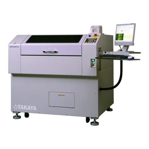
TAKAYA APT-9411 Series Manual

TAKAYA
Extension Scanner Board
ESC-9500 Operator s Guide


APT-9411 Extension Scanner Board
- 1 -
Preface
The Extension Scanner Board ESC-9500 is an option integrated into the TakayaFixtureless tester
APT-9411 Series and the sister models to extend its capabilities.
Please read this manual thoroughlybefore using this option. Then keep this manual handyfor answers
to anyquestions youmayhave.
If you have anyquestions or thoughtsyouwould like toshare with us wewould like to hear fromyou.
(NOTE)
1) The designoftheproductand softwareareunderconstant review and whileevery effort is made to
keep this manual upto date, wereserve the rightsto change specifications and equipment at any
time without prior notice.
2) Windows®,Windows®NT is a registered trademarkofMicrosoft Corporation.Also thecompany
name and the product name listed in this User’s guide are thetrademarkofeach company.
3) No portion ofthe contentsof this publication maybe reproduced or transmitted in any formor by any
means without the express writtenpermission ofTAKAYACORP.

- 2 -
Introduction
Safetysymbols
Symbol
Explanation
Calls attention to a procedure, practice, or condition that could possiblycause
serious accident or death.
Calls attention to a procedure, practice, or condition that could possiblycause
bodilyinjuryor damageto theproduct.
Calls attention to aprocedure, practice, orcondition that could possibly
damage to the product.
Calls attentiontogeneralinstruction.
Failingtofollowthis could loss ofdata storedondiskscausespossibly
misjudgetheunit under test, or damage to the product.
Calls attention to “One-point advice”which shouldbe useful when you are at a
loss tooperate the products.

APT-9411 Extension Scanner Board
- 3 -
Extension Scanner Board
Byintegrating the Extension Scanner Board ESC-9500 (hereinafter called “ESC-9500”)into the
APT-9411 Series and the sister models, the user is able to use max. 64 extension bottom probes
(option) for applying the measuring signals to the UUT. Usuallythe measuring signal to the UUT is
appliedthrough the extension bottom probes, but it is also possible for the userto use adedicated
underside fixture jig or plugin the connector directlyinto theUUT.
System Configuration
Hardware
The ESC-9500 consists of the following components:
PCB Takaya TVX-14 x 1 Pc
Connecting cable Takaya WS-635-01 (TVX-14 PCB ~ Tray) x 1 Pc
Connecting cable Takaya WS-635-02 (TVX-14 PCB ~ Tray) x 1 Pc
Connector cable Takaya HS-645-01 (Tray ~ UUT) x 1 Pc
(Remarks) The extension bottom probes are extra-costoption to be sold as needed.
The TVX-14 PCB, as the major component ofthe ESC-9500, should be installedin the slot #11 ofthe
standard rackin the tester.
[Fig.1] Installation ofTVX-14 PCB
[Fig.2]
APT-9411 Tray
Measurement rack
Bottom Probe
or
Connector etc
CN3
CN4
TVX-14
HS-645-01
WS-635-01
(1-32pin)
WS-635-02
(33-64pin)
Fig.A
Fig.B
APT-9411
Close up
TVX-14 PCB
Standard rack
Slot #11
CN4
CN3
Cable WS-635-02
Cable WS-635-01
Bar to prevent PCBs from falling off

- 4 -
[Fig.3]
WS-635-01 TVX-14 (CN3)
WS-635-02 TVX-14 (CN4)
1pin 1 1pin 33
2pin 2 2pin 34
| | | |
31pin 31 31pin 63
32pin 32 32pin 64
33pin GND 33pin GND
34pin GND 34pin GND
(Cableconnection between TVX-14 PCB and WS-635-01/02)
[Fig.4]
Software
The ESC-9500 will be recognized automatically at thetime ofstartup.
(Important reminder)
1. Ifonce the test steps bymaking use ofthe ESC-9500 are changed to the following steps, the pin
numbers will be initialized and get touse the flying probes:
•Visiontest step
•Special generation step (CM-)
•IC Opentest step (ICOP)
•Digital transistor step (DGTR)
•Pattern open checkstep (PT-)
•Photo coupler test step(PC)
•Kelvin measurement step (Kel.)
•I/O step
2. The ESC-9500 should be used for normal (MDA) test steps only,notfor the steps to measure high
voltage or large current.
WS-635-01 (1-32pin)
WS-635-02 (33-64pin)
HS-645-01
Fig.A
HS-645-01
Fig.B
1
2
3
4
31
32
33
34

APT-9411 Extension Scanner Board
- 5 -
Test Data Generation
Basic data generation
Listedbelowis the operating procedure to add new basic data usingthe extension bottomprobes.
[ Operating procedure ]
1. Clickon Step Edit (or Step List) fromEdit menu ontheMenu bar.
2. It displays “Enterstep number (1 x)”.Use thekeyboard toenter the step number andclickon the
OK button.(Fig.5 indicates a case ofgenerating a new step atStep 000008)
Teaching system Point system
[Fig.5] Step edit list
3. Use the keyboard to enter “Parts”, “Value, and “Comment”in order. For Point system(the right
screen in Fig.6), you candispense with “H-pin”and “L-pin”.
Teaching systemPoint system
[Fig.6] Step edit list
4. Use your mouse to select “Tool”>“Bottomprobe”> “Bottomprobe”> “Set”in order.
[Fig.7]

- 6 -
5. It displays the Bottomprobe setting screen (Fig.8).
[Fig.8] Bottomprobe
6. Fill thebox “Polarity+”and select “Extension Scanner (64pin)”fromthe rightpull-down menu.
[Fig.9]
7. Specifythe extension bottom probe to use for applying the measuring signal.
[Fig.10]
8. Onlyif you want to use the extension bottomprobe for “Polarity -”as well, select “Extension
Scanner (64pin)”fromthe right pull-down menu andspecify extension bottomprobe to use. (Refer
to Fig.11) Then Clickthe OK button.
[Fig.11]

APT-9411 Extension Scanner Board
- 7 -
9. The display goes backto Fig.12.Nowyou can see theBottomprobe column in theStep edit list is
substituted bythe symbol of “E1, N, N, E2”.
[ E1 ] means the extensionbottomprobe#1. [ E2 ] means the extension bottomprobe#2.
[Fig.12]
Automatic generation function
Listed belowis the operating procedure to add new basic data using the extensionbottomprobes with
Automatic generationfunction. Let’s take“Pin to ground”stepsofIC asanexample to explainAutomatic
generation function in a wayeasyto understand.
[ Operating procedure ]
1. Clickon Step Edit (or Step List) fromEdit menu ontheMenu bar.
2. It displays “Enterstep number (1 x)”.Use thekeyboard toenter the step number andclickon the
OK button.(Fig.13 indicates a case ofgenerating a newstep at Step 000008)
[Fig.13] Step edit list
3. Use the keyboard to enter “Parts”and clickon “A.Gen.”icon onthe Tool bar, and Fig.14 will be
displayed.
[Fig.14] Automatic generation

- 8 -
4. Makeaseries ofprogramming stepstogenerate “Pin toground”stepsofIC according to the menu
guidance until Fig.15 appears on the display.
Teaching systemPoint system
[Fig.15]
5. Specifythe ground pin number and fill thebox “Use Bottomground”.
[Fig.16]
6. Select “Extension Scanner (64pin)”fromthe right pull-down menu and specifythe Ground pin
number on the bottom.
[Fig.17]
7. ClicktheNext buttonand continue generatingtheIC open teststepsaccording tothemenu
guidance. Fig.18 indicates a sample ofthe IC open test steps generated.
Teaching systemPoint system
[Fig.18]

APT-9411 Extension Scanner Board
- 9 -
8. Nowyoucansee on theStep edit list that theBottomprobecolumnis substituted by thesymbol of
“E11”.
[ E11 ] means the extension bottomprobe #11.
[Fig.19]
Setup the extension bottom probes in the existingstep data
Listed belowis the operating procedure tochange theexisting stepdata so as to use the extension
bottomprobes. The explanation is written for Point system, but basicallythe operating procedure in the
Teaching system is the same.
Setup on Step / Edit list
[ Operating procedure ]
1. Clickon Step Edit (or Step List) fromEdit menu ontheMenu bar.
2. It displays “Enterstep number (1 x)”.Use thekeyboard toenter the step number andclickon the
OK button.(Fig.20 indicates a case ofchangingStep 000008)
[Fig.20]
3. Use your mouse to select “Tool”>“Bottomprobe”> “Bottomprobe”> “Set”in order.
[Fig.21]

- 10 -
4. It displays the Bottomprobe setting screen (Fig.22).
[Fig.22] Bottomprobe
5. Fill either thebox “Polarity+”or “Polarity ” that should be changed from the flying probeto the
extension bottomprobe. In the case ofStep 000001 in Fig.23 below, Polarity column is substituted
by the symbol of “+,N,N,-”. It means that Probe 1 is “Polarity+”and Probe 4 is “Polarity ”.
[Fig.23]
6. Fill thebox “Polarity+”and select “Extension Scanner (64pin)”fromthe rightpull-down menu.
[Fig.24]
7. Specify the extension bottomprobe to use.
[Fig.25]
8. Onlyifyou want to use the extension bottomprobe for “Polarity -”as well, select “Extension
Scanner (64pin)”fromthe rightpull-downmenu andspecify the extensionbottomprobe to use.
Then Clickthe OK button.
[Fig.26]

APT-9411 Extension Scanner Board
- 11 -
9. The display goes backto Fig.27.Nowyou can see theBottomprobe column in theStep edit list is
substituted bythe symbol of “E11, N, N, E12”.
[ E11 ] means the extension bottomprobe #11. [ E12 ]means the extension bottomprobe #12.
[Fig.27]
Setup on Step data review
1. Go to the step that should be changed fromthe flying probe to the extensionbottomprobe in Step
data review.
[Fig.28] Step data review
2. Clickon [ Probe Access ] todisplaythe pull-down menu. (Refer to Fig.29)
[Fig.29] ProbeAccess

- 12 -
3. Select [BottomSet] fromthe pull-down menu, and it displays the Bottomprobe setting screen.
[Fig.30]Bottomprobe
4. Fill either thebox “Polarity+”or “Polarity ” that should be changedfromthe flying probeto the
extensionbottomprobe. Inthe coordinates shown in Fig.31, Probe1is “Polarity+”and Probe4is
“Polarity “.
[Fig.31]
5. Fill thebox “Polarity+”and select “Extension Scanner(64pin)”fromthe rightpull-down menu.
[Fig.32]
6. Specifythe extension bottomprobe to use.
[Fig.33]
7. Onlyifyou want to use the extension bottomprobe for “Polarity -”as well, select “Extension
Scanner(64pin)”fromthe right pull-down menu and specifythe extension bottom probe to use.
(Refer to Fig.34) Then Click the OK button.
[Fig.34]

APT-9411 Extension Scanner Board
- 13 -
8. The display goes backto Fig.35.Nowyou can see theBottomprobe column is substituted bythe
symbol of “E1, N, N, E2”.
[ E1 ] means the extensionbottomprobe #1. [E2] means the extension bottomprobe #2.
[Fig.35]

- 14 -
Change ground pin of IC to the bottom
Listedbelowis theoperating procedure tochangetheground pin usedin theexisting “Pin toground”
steps to the extensionbottomprobe. The explanationis made for Teaching systemand Point system
separately.
[ Operating procedure (by Teaching system) ]
1. Clickon Step Edit (or Step List) fromEdit menu ontheMenu bar.
2. Use your mouse to select “Tool”> “Bottomprobe”> “Change Ground Pin for BottomProbe”in order.
[Fig.36]
3. It displays the Change Ground Pin for BottomProbe screen.
[Fig.37] Change Ground Pin for BottomProbe
4. Typethe search string(ex.IC1) in the Search partscolumnand click theSearch button at theright.
Then “IC1”is displayed in the Object parts column as shownin Fig.38.
[Fig.38]

APT-9411 Extension Scanner Board
- 15 -
5. Use your mouse to select “IC1”andclickthe Select button, and “IC1”is displayedinthe Select parts
column as shown in Fig.39.
[Fig.39]
6. Select “Extension Scanner(64pin)”fromthe right pull-downmenu at Specify thebottomground and
specify the extension bottomprobe.
[Fig.40]
7. Clickthe Execute button to execute your change. Nowyou can see on the Step edit list that the
Bottomprobe column ofIC1 is substituted bythe symbol of “E11”.
[Fig.41]
At the operatingprocedure#4, ifyou use wildcard character in thesearched partsname
such like “IC*”,all ICcomponentswiththeregisterednamestarting fromIC will be listed
in the Object parts column:
So it becomes that much easier to change the ground pin of lot of ICs to the extension
bottomprobe.

- 16 -
[ Operating procedure (byPoint system) ]
1. Clickon Step Edit (or Step List) fromEdit menu ontheMenu bar.
2. Use your mouse to select “Tool”> “Bottomprobe”> “Assign Netto BottomProbe”in order.
[Fig.42]
3. It displays the Assign Net to BottomProbe screen.
[Fig.43] Assign Netto BottomProbe
Use the Specifythe Pin number columnto select thepin number that shouldbe change to the
extension bottomprobe.
[Fig.44]
It’salsopossible for you to select the netname(Ex.GND) fromthe rightpull-down
menu, so that the pin number used on the net is substituted in the SpecifythePin
number column automatically. When thereare more than onepinnumber areused on
the same net, the youngestpinnumber will be substituted.
Ifyouwanttochangeall pinsused on thesamenet at one time, fill thefollowingboxon
the screen
Select “ExtensionScanner (64pin)”fromthe right pull-downmenu at Specifythebottomprobe
number and specify the extension bottomprobe.
[Fig.45]

APT-9411 Extension Scanner Board
- 17 -
Clickthe OK button to execute your change.
[Fig.46]
4. Nowyou can see on the Step edit list that Pin #1 is substituted bythe symbol of “E11”.
[Fig.47]

- 18 -
Cancel the extension bottom probes
Listed belowis theoperatingprocedure tochange theexistingstep data so as to cancel the extension
bottomprobe. The operating procedure is the same in both the Teachingsystem and the Point system.
[ Operating procedure ]
1. Clickon Step Edit (or Step List) fromEdit menu ontheMenu bar.
2. It displays “Enterstep number (1 x)”.Use thekeyboard toenter the step number andclickon the
OK button.(Fig.48 indicates the extension bottomprobe is used on Step 000008)
[Fig.48]
3. Use your mouse to select “Tool”> “Bottomprobe”> “Bottomprobe”> “Release”inorder.
[Fig.49]
4. It displays the Releasebottomprobe screen.
[Fig.50] Release bottomprobe
Other manuals for APT-9411 Series
3
This manual suits for next models
1
Table of contents
Other TAKAYA Test Equipment manuals