25% Step Current Output
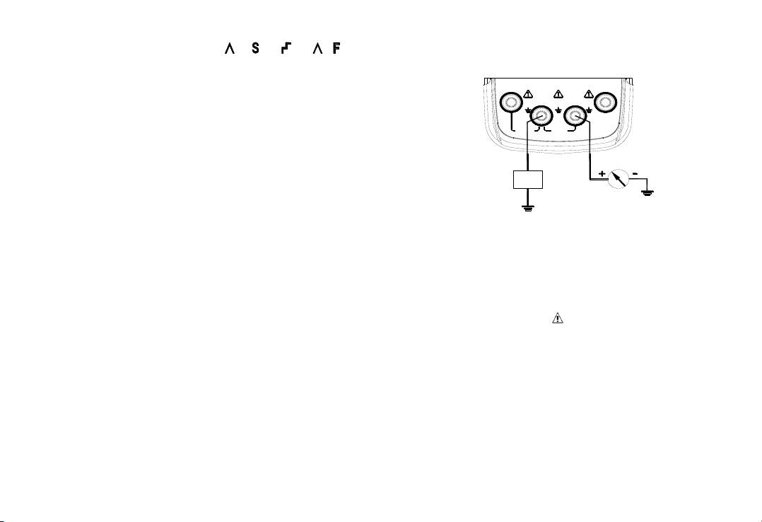
1) Connect to the Instrument as shown in Figure
5-1;
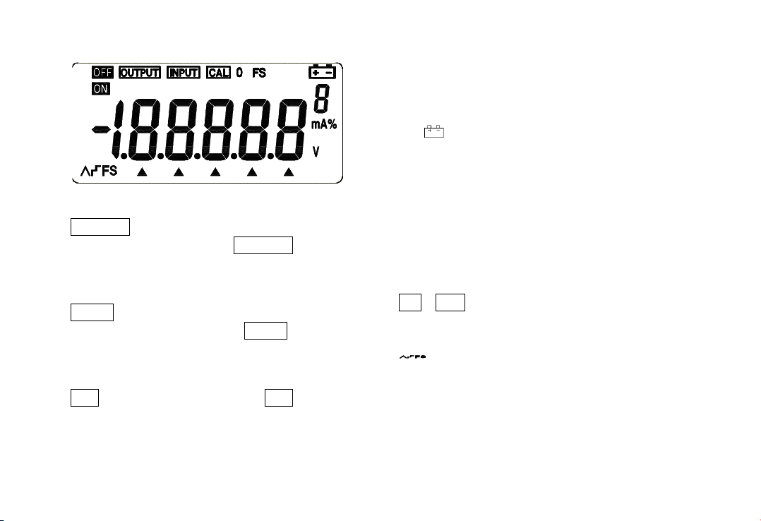
2) When the key〔OUTPUT/IN〕is pressed, the
OUTPUT appears in the LCD, it denotes the
Instrument is in an output state;
3) Press the key〔25%/RAMP〕and the
symbols‘ ’ and ‘’will appear;
4) Press the key 〔mA%/ V〕to select the
output to be set in mA or %, and then the unit
‘mA’or‘mA % appears;
5) Press the key 〔〕/〔〕to change the
output in a value of 25%, in which 0% denotes
4mA and 100% denotes 20mA;
6) Repress the key〔25%/RAMP〕so as to exit
the step current output.
Current Output Set for Zero Point & Full Scale
1) Connect to the Instrument as shown in Figure
5-1;
2) When the〔OUTPUT/IN〕key is pressed, the
OUTPUT appears in the LCD, it denotes the
Instrument is in an output state;
3) Press the key 〔100%/START〕and the
symbols ‘ ’、‘’、‘0’、‘FS’ will appear in the
display;
4) Press the key〔〕to be set to 100% and the
current output will be 20mA. Press the
key〔〕to be set to 0% and the current
output will be 4mA;
5) Repress the key〔100%/START〕so as to exit
the step current output.
Auto-ramp Output
1) Connect as shown in Figure 5-1;
2) When the key〔OUTPUT/IN〕is pressed, the
OUTPUT appears in the LCD, it denotes the
Instrument is in an output state;
3) When the key〔STEP/AUTO〕is pressed, the
symbols ‘OUTPUT’, ‘OFF’, ‘ ’along with
‘4mA’ appear in the LCD. If so, it denotes that
the Instrument is getting into the mode of
RAMP;
4) Repress the key〔25%/RAMP〕again so as to
change the type of the output ramp, which
finds itself in the lower left of the LCD. The